CN212640802U - A pressing device on a sewing machine - Google Patents

A pressing device on a sewing machine Download PDF

Info

Publication number
CN212640802U
CN212640802U CN202021144563.5U CN202021144563U CN212640802U CN 212640802 U CN212640802 U CN 212640802U CN 202021144563 U CN202021144563 U CN 202021144563U CN 212640802 U CN212640802 U CN 212640802U
Authority
CN
China
Prior art keywords
pressing
presser foot
pressing part
cloth
handle
Prior art date
Legal status (The legal status is an assumption and is not a legal conclusion. Google has not performed a legal analysis and makes no representation as to the accuracy of the status listed.)
Expired - Fee Related
Application number
CN202021144563.5U
Other languages
Chinese (zh)
Inventor
温月微
何建聪
周瑜
Current Assignee (The listed assignees may be inaccurate. Google has not performed a legal analysis and makes no representation or warranty as to the accuracy of the list.)
Zhejiang Elda Industrial Co ltd
Original Assignee
Zhejiang Elda Industrial Co ltd
Priority date (The priority date is an assumption and is not a legal conclusion. Google has not performed a legal analysis and makes no representation as to the accuracy of the date listed.)
Filing date
Publication date
Application filed by Zhejiang Elda Industrial Co ltd filed Critical Zhejiang Elda Industrial Co ltd
Priority to CN202021144563.5U priority Critical patent/CN212640802U/en
Application granted granted Critical
Publication of CN212640802U publication Critical patent/CN212640802U/en
Expired - Fee Related legal-status Critical Current
Anticipated expiration legal-status Critical

Links

Images

Landscapes

  • Sewing Machines And Sewing (AREA)

Abstract

本实用新型公开了一种缝纫机上的压紧装置,压脚组件包括第一压脚端和第二压脚端,第二压脚端上设有开口槽,压脚柄上设有压布组件,压布组件包括扣架、前侧压部和后侧压部,后侧压部包括压臂和滚轮,压臂与压脚柄之间呈预定角度的倾斜设置,滚轮的轴线垂直布料的移动方向,前侧压部包括左压件和右压件,左压件和右压件均包括压杆和底部的压轮,扣架上设有穿设槽,压杆的一端位于穿设槽内转动配合,压杆与压脚柄之间呈预定角度的倾斜设置,压杆上设有限位片,压脚柄上设有限位环,限位环上具有缓冲槽口,限位片穿设于缓冲槽口内,缓冲槽口的两侧壁上设有缓冲件,缓冲件与限位片相抵触。改进后,提升了缝纫的质量,提升了产品的合格率。

Figure 202021144563

The utility model discloses a pressing device on a sewing machine. A presser foot assembly includes a first presser foot end and a second presser foot end. The second presser foot end is provided with an opening groove, and the presser foot handle is provided with a cloth presser assembly. , the cloth pressing assembly includes a buckle frame, a front side pressing part and a rear side pressing part, the rear side pressing part includes a pressing arm and a roller, the pressing arm and the presser foot handle are inclined at a predetermined angle, and the axis of the roller is perpendicular to the movement of the cloth The front side pressing part includes a left pressing piece and a right pressing piece. Both the left pressing piece and the right pressing piece include a pressing rod and a pressing wheel at the bottom. The buckle frame is provided with a penetration groove, and one end of the pressing rod is located in the penetration groove Rotating and cooperating, the pressure rod and the presser foot handle are inclined at a predetermined angle, the pressure rod is provided with a limit piece, the presser foot handle is provided with a limit ring, the limit ring is provided with a buffer notch, and the limit piece passes through the In the buffer slot, two side walls of the buffer slot are provided with buffer pieces, and the buffer pieces collide with the limit pieces. After the improvement, the quality of sewing has been improved, and the qualified rate of products has been improved.

Figure 202021144563

Description

Pressing device on sewing machine
Technical Field
The utility model relates to a sewing machine equipment field, more specifically say, it relates to a closing device on sewing machine.
Background
The sewing machine is a machine which uses one or more sewing threads to form one or more stitches on a sewing material so as to interweave or sew one or more layers of the sewing material; the sewing machine comprises a presser foot mechanism which is mainly used for pressing cloth, so that the cloth is not easy to shrink and swing left and right, and the cloth is conveyed in a way of being matched with the cloth feeding teeth. The existing sewing machine presser foot has the problem of uneven cloth pressing, so that a sewing thread is bent when walking, or the cloth has wrinkles, so that the sewing quality is unstable, and the qualified rate is influenced.
SUMMERY OF THE UTILITY MODEL
Not enough to prior art exists, the utility model aims to provide a sewing thread walks to position more level and more smooth, promotes the closing device on the sewing machine of the planarization of cloth when sewing.
In order to achieve the above purpose, the utility model provides a following technical scheme: a pressing device on a sewing machine comprises a presser foot handle and a presser foot component, wherein the presser foot component comprises a first presser foot end and a second presser foot end positioned in the first presser foot end, an open slot for a sewing needle to penetrate is formed in the second presser foot end, a cloth pressing component is arranged on the presser foot handle and comprises a buckle frame, a front side pressing part and a rear side pressing part which are positioned at two ends of the buckle frame, the rear side pressing part comprises a pressing arm and a roller, the pressing arm and the presser foot handle are obliquely arranged at a preset angle, the axis of the roller is vertical to the moving direction of cloth, the front side pressing part comprises a left pressing part and a right pressing part, the left pressing part and the right pressing part respectively comprise a pressing rod and a pressing wheel at the bottom, a penetrating slot is formed in the buckle frame, one end of the pressing rod is positioned in the penetrating slot and rotationally matched, the pressing rod and the presser foot handle are obliquely arranged at a preset angle, a limiting piece is arranged on the pressing rod, the presser foot handle is provided with a limiting ring, the limiting ring is provided with a buffer notch, the limiting sheet is arranged in the buffer notch in a penetrating mode, two side walls of the buffer notch are provided with buffer pieces, and the buffer pieces are abutted to the limiting sheet.
The utility model discloses further set up to: the pinch roller includes wheel body and shaft, the tip of shaft is equipped with the dog, be equipped with on the depression bar and supply the dog to insert the spout of establishing, be equipped with the spring on the inner wall of spout, the spring is contradicted with the one end of dog, and the other end of ordering about the dog is inconsistent with the inner wall of spout.
The utility model discloses further set up to: the presser foot is characterized in that the buckle frame is provided with a sliding block and a threaded hole, the presser foot handle is provided with a longitudinal slide way, and the bottom wall of the slide way is provided with a mounting hole.
The utility model discloses further set up to: one end of the pressing arm is arranged on the buckling frame in a swinging mode through the rotating shaft.
Through adopting above-mentioned technical scheme, the cloth is not only suppressed by first presser foot end when sewing, and the periphery of cloth can also be suppressed by the compress subassembly, does benefit to the planarization that promotes the cloth when making up, promotes the quality of sewing. Meanwhile, the structure of the open slot is arranged at the end of the second presser foot, so that an operator can observe the position of the wiring from the position of the open slot in time, deviation is avoided, and the sewing quality is improved.
Drawings
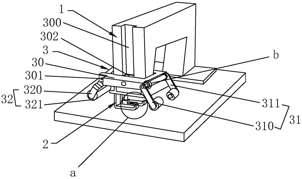
FIG. 1 is a schematic structural view of the present invention;
FIG. 2 is an enlarged view of a portion a of FIG. 1;
FIG. 3 is an enlarged view of FIG. 1 at b;
FIG. 4 is a sectional view showing a partial structure of a front press portion;
fig. 5 is a partial structural sectional view of the presser foot handle and the buckle holder.
1. A presser foot handle; 10. a limiting ring; 11. a buffer notch; 12. a buffer member; 13. mounting holes; 2. a presser foot assembly; 20. a first presser foot end; 21. a second presser foot end; 210. an open slot; 3. a cloth pressing component; 30. buckling frames; 300. a slideway; 301. a rotating shaft; 302. a slider; 303. a threaded hole; 31. a front side pressing portion; 310. a left pressing piece; 311. a right pressing piece; 312. a pressure lever; 313. a groove is arranged in a penetrating way; 314. a pinch roller; 315. a wheel body; 316. a wheel axle; 317. a stopper; 318. a chute; 319. a spring; 32. a rear side pressing part; 320. pressing the arm; 321. a roller; 330. a limiting sheet.
Detailed Description
The embodiments of the present invention are further described with reference to fig. 1 to 5, and the technical solutions in the embodiments of the present invention are clearly and completely described, and it is obvious that the described embodiments are only some embodiments of the present invention, but not all embodiments. Based on the embodiments in the present invention, all other embodiments obtained by a person skilled in the art without creative work belong to the protection scope of the present invention.
A pressing device on a sewing machine comprises a presser foot handle 1 and a presser foot component 2, wherein the presser foot component 2 comprises a first presser foot end 20 and a second presser foot end 21 positioned in the first presser foot end 20, the second presser foot end 21 is provided with an open slot 210 for a sewing needle to penetrate through, the presser foot handle 1 is provided with a cloth pressing component 3, the cloth pressing component 3 comprises a buckle frame 30, a front side pressing part 31 and a rear side pressing part 32 positioned at two ends of the buckle frame 30, the rear side pressing part 32 comprises a pressing arm 320 and a roller 321, the pressing arm 320 and the presser foot handle 1 are obliquely arranged at a preset angle, the axis of the roller 321 is vertical to the moving direction of cloth, the front side pressing part 31 comprises a left presser 310 and a right presser 311, the left presser 310 and the right presser 311 both comprise a pressing rod 312 and a pressing wheel 314 at the bottom, the buckle frame 30 is provided with a penetrating slot 313, one end of the pressing rod 312 is positioned in the penetrating slot 313 for rotating fit, the utility model discloses a presser foot, including depression bar 312, presser foot handle 1, be equipped with spacing piece 330 on the depression bar 312, be equipped with spacing ring 10 on the presser foot handle 1, buffer slot 11 has on the spacing ring 10, spacing piece 330 wears to locate in buffer slot 11, be equipped with bolster 12 on the both sides wall of buffer slot 11, bolster 12 is inconsistent with spacing piece 330. The pinch roller 314 comprises a roller body 315 and a roller shaft 316, a stop block 317 is arranged at the end of the roller shaft 316, a sliding groove 318 for the stop block 317 to insert is arranged on the compression bar 312, a spring 319 is arranged on the inner wall of the sliding groove 318, the spring 319 abuts against one end of the stop block 317, and the other end of the stop block 317 is driven to abut against the inner wall of the sliding groove 318. The buckle frame 30 is provided with a sliding block 302 and a threaded hole 303, the presser foot handle 1 is provided with a longitudinal slide 300, and the bottom wall of the slide 300 is provided with a mounting hole 13. One end of the pressing arm 320 is arranged on the buckle frame 30 through the rotating shaft 301 in a swinging manner.
The cloth to be sewn is located below the presser foot assembly 2, the first foot end and the second foot end 21 on the presser foot assembly 2 tightly press the cloth, and a sewing needle falls into an open slot 210 of the second foot end 21 to sew the cloth. The open slot 210 is arranged in a trumpet shape, so that an operator can observe the trend of the sewing thread conveniently, and the phenomenon that the sewing thread deviates to cause low sewing quality is avoided.
The cloth is pressed by the presser foot assembly 2, and the peripheral part of the cloth is pressed by the cloth pressing assembly 3. The pressing wheel 314 on the front pressing part 31 and the roller 321 on the rear pressing part 32 can compress the cloth, expand the pressing range of the cloth and are beneficial to improving the smoothness of cloth sewing. The pressing rod 312 on the front side pressing portion 31 can press the buffering member 12 in the buffering groove opening 11 through the limiting piece 330 to contract, so that the position adjustment of the pressing rod 312 in a small range is realized, and the buffering member 12 can be a spring. In the process of advancing and conveying the cloth, the effect of buffering is achieved, and cloth wrinkles caused by over-tight pressing are avoided. The pinch roller 314 is contracted by the spring 319 to realize a small-range displacement of the stop 317 in the sliding groove 318 of the compression bar 312, thereby playing a role in adjusting the height of the pinch roller 314. The front pressing part 31 comprises a left pressing piece 310 and a right pressing piece 311, and a space is formed between the left pressing piece 310 and the right pressing piece 311, so that an operator can conveniently check the sewing effect of the sewing needle. The front side pressing portion 31 and the rear side pressing portion 32 are located on the buckling frame 30, the buckling frame 30 is matched with the slide rail 300 on the presser foot handle 1 through the sliding block 302, position fixing is achieved, then the bolt penetrates through the threaded hole 303 and the mounting hole 13 to be located, the detachable structure is achieved, when the cloth pressing assembly 3 does not need to be used, the detachable cloth pressing assembly can be detached and stored, and operation is convenient and fast.
The points to be finally explained are: first, in the description of the present application, it should be noted that, unless otherwise specified and limited, the terms "mounted," "connected," and "connected" should be understood broadly, and may be a mechanical connection or an electrical connection, or a communication between two elements, and may be a direct connection, and "upper," "lower," "left," and "right" are only used to indicate a relative positional relationship, and when the absolute position of the object to be described is changed, the relative positional relationship may be changed;
secondly, the method comprises the following steps: in the drawings of the disclosed embodiments of the present invention, only the structures related to the disclosed embodiments are referred to, and other structures can refer to the common design, and under the condition of no conflict, the same embodiment and different embodiments of the present invention can be combined with each other;
finally, it is only above the preferred embodiment of the present invention, the protection scope of the present invention is not limited to the above embodiments, all belong to the technical scheme of the present invention under the thought all belong to the protection scope of the present invention. It should be noted that, for those skilled in the art, various modifications and decorations can be made without departing from the principle of the present invention, and these modifications and decorations should also be regarded as the protection scope of the present invention.

Claims (4)

1. The utility model provides a closing device on sewing machine, includes presser foot handle and presser foot subassembly, its characterized in that: the presser foot component comprises a first presser foot end and a second presser foot end positioned in the first presser foot end, the second presser foot end is provided with an open slot through which a sewing needle passes, the presser foot handle is provided with a cloth pressing component, the cloth pressing component comprises a buckle frame, a front side pressing part and a rear side pressing part, the front side pressing part and the rear side pressing part are positioned at two ends of the buckle frame, the rear side pressing part comprises a pressing arm and a roller, the pressing arm and the presser foot handle are obliquely arranged at a preset angle, the axis of the roller is vertical to the moving direction of cloth, the front side pressing part comprises a left pressing part and a right pressing part, the left pressing part and the right pressing part both comprise a pressing rod and a pressing wheel at the bottom, the buckle frame is provided with a through slot, one end of the pressing rod is positioned in the through slot in a rotating fit manner, the pressing rod and the presser foot handle are obliquely arranged at a preset angle, the pressing rod is provided with a limiting sheet, the presser foot handle is, the limiting piece penetrates through the buffer notch, buffer pieces are arranged on two side walls of the buffer notch, and the buffer pieces are abutted to the limiting piece.
2. The pressing device of a sewing machine according to claim 1, wherein: the pinch roller includes wheel body and shaft, the tip of shaft is equipped with the dog, be equipped with on the depression bar and supply the dog to insert the spout of establishing, be equipped with the spring on the inner wall of spout, the spring is contradicted with the one end of dog, and the other end of ordering about the dog is inconsistent with the inner wall of spout.
3. The pressing device of a sewing machine according to claim 2, wherein: the presser foot is characterized in that the buckle frame is provided with a sliding block and a threaded hole, the presser foot handle is provided with a longitudinal slide way, and the bottom wall of the slide way is provided with a mounting hole.
4. The pressing device of a sewing machine according to claim 1, wherein: one end of the pressing arm is arranged on the buckling frame in a swinging mode through the rotating shaft.
CN202021144563.5U 2020-06-18 2020-06-18 A pressing device on a sewing machine Expired - Fee Related CN212640802U (en)

Priority Applications (1)

Application Number Priority Date Filing Date Title
CN202021144563.5U CN212640802U (en) 2020-06-18 2020-06-18 A pressing device on a sewing machine

Applications Claiming Priority (1)

Application Number Priority Date Filing Date Title
CN202021144563.5U CN212640802U (en) 2020-06-18 2020-06-18 A pressing device on a sewing machine

Publications (1)

Publication Number Publication Date
CN212640802U true CN212640802U (en) 2021-03-02

Family

ID=74771079

Family Applications (1)

Application Number Title Priority Date Filing Date
CN202021144563.5U Expired - Fee Related CN212640802U (en) 2020-06-18 2020-06-18 A pressing device on a sewing machine

Country Status (1)

Country Link
CN (1) CN212640802U (en)

Cited By (2)

* Cited by examiner, † Cited by third party
Publication number Priority date Publication date Assignee Title
CN114769382A (en) * 2022-04-29 2022-07-22 湖北恒信铭扬置业集团有限公司 C-shaped steel processing equipment and processing technology
CN118895614A (en) * 2024-08-29 2024-11-05 浙江丰绩服饰科技有限公司 A material pressing device for a sewing machine

Cited By (3)

* Cited by examiner, † Cited by third party
Publication number Priority date Publication date Assignee Title
CN114769382A (en) * 2022-04-29 2022-07-22 湖北恒信铭扬置业集团有限公司 C-shaped steel processing equipment and processing technology
CN114769382B (en) * 2022-04-29 2025-11-04 湖北恒信铭扬置业集团有限公司 A C-shaped steel processing equipment and processing technology
CN118895614A (en) * 2024-08-29 2024-11-05 浙江丰绩服饰科技有限公司 A material pressing device for a sewing machine

Similar Documents

Publication Publication Date Title
WO2009129644A1 (en) A fully automatic closing sewing machine
JPS6214315B2 (en)
CN207672235U (en) A kind of leatherware sewing machine
CN201031301Y (en) Improved structure of rolling feeding for sewing machine
CN207812044U (en) A kind of sewing-machine foot device
US2170948A (en) Sewing machine
US2873704A (en) Mechanism for operating on tubular blanks
US2489489A (en) Sewing machine for stitching leather cases
CN220246414U (en) Sewing device for clothing production
CN113969470A (en) Novel embroidery sheet tucking and sheet feeding mechanism thereof
TWM250948U (en) Fabric guide device for a sewing machine
US319740A (en) Method of forming insoles for shoes
US1837468A (en) Sewing machine feeding mechanism
CN216040129U (en) Sewing machine presser foot assembly and sewing machine with same
CN221822516U (en) Buttonhole sewing machine
JPH0418549Y2 (en)
CN216639861U (en) Intelligent serging machine of easy operation
JP2003190684A (en) Presser bar lifting device of sewing machine
US2869492A (en) Feeding and guiding mechanism for sewing machines
US2337631A (en) Shoe sewing machine
US2807225A (en) Cording presser-foot for sewing machines
US2158246A (en) Blind stitch sewing machine
CN209741400U (en) Roll down pendulum presser foot assembly
US1103795A (en) Sewing-machine guide.
US343669A (en) Combined sewing-machine and work-holding frame for stitching the insoles of shoes

Legal Events

Date Code Title Description
GR01 Patent grant
GR01 Patent grant
CP02 Change in the address of a patent holder

Address after: 314300 108 Jinqiao Road, Yucheng Town, Haiyan County, Jiaxing City, Zhejiang Province

Patentee after: Zhejiang Elda Industrial Co.,Ltd.

Address before: No.2112, South Baixiang section, 104 National Highway, nanbaixiang street, Ouhai District, Wenzhou City, Zhejiang Province, 325000

Patentee before: Zhejiang Elda Industrial Co.,Ltd.

CF01 Termination of patent right due to non-payment of annual fee

Granted publication date: 20210302