CN212683080U - Automatic screw feeding machine - Google Patents
Automatic screw feeding machine Download PDFInfo
- Publication number
- CN212683080U CN212683080U CN202021446647.4U CN202021446647U CN212683080U CN 212683080 U CN212683080 U CN 212683080U CN 202021446647 U CN202021446647 U CN 202021446647U CN 212683080 U CN212683080 U CN 212683080U
- Authority
- CN
- China
- Prior art keywords
- screw
- plate
- feeding
- fixedly connected
- rail
- Prior art date
- Legal status (The legal status is an assumption and is not a legal conclusion. Google has not performed a legal analysis and makes no representation as to the accuracy of the status listed.)
- Active
Links
Images


Landscapes
- Details Of Spanners, Wrenches, And Screw Drivers And Accessories (AREA)
Abstract
The utility model relates to the technical field of machining, this automatic screw machine of going up, which comprises a worktable, there is the support column frame one end at board top through screw fixed mounting, there is the screw placer on the top of support column frame through screw fixed mounting, the first pipeline of bottom fixedly connected with of screw placer, station mechanism about the one end fixedly connected with of first pipeline, control the one end fixedly connected with second pipeline of station mechanism, the second pipeline is kept away from the one end and the board fixed connection of controlling station mechanism. The utility model has the advantages that: this automatic screw machine of going up makes the screw on the top of blowing frame slide along the arc wall of pay-off location slide rail, makes the screw on blowing frame top drive the blowing frame and remove along the spout of pay-off slide rail, carries the top of first pipeline one end with the screw, makes the screw remove the screw through first pipeline and presss from both sides automatically, and then can effectually carry out automatic transport to the screw, has avoided the time of shutting down the installation screw.
Description
Technical Field
The utility model relates to the technical field of machining, especially an automatic screw machine of going up.
Background
The screw is a tool for fastening machine parts of the object step by utilizing the physics and mathematical principles of the inclined plane circular rotation and the friction force of the object, the screw is a general term of a fastener, and the screw is an indispensable industrial necessity in daily life in a daily oral language: extremely small screws used for cameras, glasses, clocks, electronics, and the like; general screws for televisions, electric appliances, musical instruments, furniture, and the like; large screws and nuts are used for engineering, buildings and bridges; transportation equipment, airplanes, electric cars, automobiles and the like are used by using large and small screws, the screws have important tasks in industry, as long as the industry exists, the functions of the screws are always important, the screws mainly connect two workpieces together to play a role in fastening, the screws are widely applied, but the screw installation has some problems:
1. the existing screw mounting equipment needs to be stopped after a screw is mounted, and the screw can be mounted again only by manually replacing the screw, so that the efficiency is low;
2. the bolt is usually installed by manual operation equipment and tools in the existing screw installation, the manual operation time is long, and the installation efficiency is low.
SUMMERY OF THE UTILITY MODEL
An object of the utility model is to overcome prior art's shortcoming, provide an automatic screw machine of going up. The purpose of the utility model is realized through the following technical scheme: an automatic screw feeding machine comprises a machine table, wherein a support column frame is fixedly arranged at one end of the top of the machine table through screws, a screw placing device is fixedly arranged at the top end of the support column frame through screws, a first pipeline is fixedly connected to the bottom of the screw placing device, a left station mechanism and a right station mechanism are fixedly connected to one end of the first pipeline, a second pipeline is fixedly connected to one end of the left station mechanism and one end of the right station mechanism, and the end, far away from the left station mechanism and the right station mechanism, of the second pipeline is fixedly connected with the machine table; the machine table comprises a machine frame, a table plate, a door plate, baffle plates and adjustable cup legs, the machine frame is fixedly connected with the table plate, the table plate is positioned at the top end of the machine frame, the middle of the machine frame is rotatably connected with the door plate, the two ends of the machine frame are fixedly connected with the baffle plates, and the bottom of the machine frame is fixedly connected with the adjustable cup legs;
the screw placer comprises a fixing plate and a screw dividing device, the fixing plate and the screw dividing device are fixedly connected through screws, and the screw dividing device is positioned at the top end of the fixing plate;
the screw dividing device comprises a fixing piece, a feeding slide rail wedge, a feeding positioning slide rail, a feeding slide rail, a discharging frame and a slide rail cylinder, wherein the middle part of the fixing piece is movably connected with the feeding slide rail;
the first pipeline comprises a connector and a pipeline body, and the two ends of the pipeline body are fixedly connected with the connectors; the left station mechanism and the right station mechanism comprise a fixing frame, a driving mechanism, an upper pneumatic mechanism, a lower pneumatic mechanism, a screw automatic clamp and a material rail mechanism, wherein the driving mechanism is fixedly connected to the top end of the fixing frame, the upper pneumatic mechanisms are fixedly connected to the tops of the two ends of the fixing frame, the lower pneumatic mechanisms are fixedly connected to the bottoms of the two ends of the fixing frame, the screw automatic clamp is fixedly mounted at one end of each lower pneumatic mechanism through screws, and the material rail mechanism is fixedly connected to the bottom of the fixing frame;
the fixing frame comprises a supporting plate, vertical plates, guide rails and a motor supporting plate, the vertical plates are fixedly arranged at two ends of the top of the supporting plate through screws, the guide rails are fixedly connected to one end of the middle of each vertical plate, and the motor supporting plate is fixedly arranged at the top ends of the vertical plates through screws;
the driving mechanism comprises a servo motor, a coupler, a universal connector, a first electric batch clamping coupling, a first bearing, a bearing seat, a second bearing, a second electric batch clamping coupling, an electric batch clamp and an electric batch head, wherein the coupler is fixedly installed on an output shaft of the servo motor, the universal connector is fixedly installed at the bottom of the coupler, the first electric batch clamping coupling is rotatably connected to the bottom of the universal connector, the first electric batch clamping coupling is inserted into the first bearing, the first electric batch clamping coupling and the first bearing are in transition fit, the first bearing is rotatably connected with the bearing seat, the first bearing is positioned at the top of the bearing seat, the bottom of the bearing seat is rotatably connected with the second bearing, the second electric batch clamping coupling is fixedly installed inside the second bearing, the second bearing and the second electric batch clamping coupling are in transition fit, and the bottom of the second electric batch clamping coupling is rotatably connected with the electric batch clamp, the bottom of the electric screwdriver clamp is fixedly connected with an electric screwdriver head;
the upper pneumatic mechanism comprises an upper air cylinder, an upper air cylinder connecting piece, an upper screwdriver support column, an electronic limiting plate and a microswitch, wherein the upper air cylinder connecting piece is fixedly installed at the bottom of the upper air cylinder through a screw, the upper air cylinder is connected with the electronic limiting plate through a screw, the upper screwdriver support column is fixedly installed at the bottom of the upper air cylinder connecting piece through a screw, the electronic limiting plate is positioned below the upper air cylinder connecting piece, the electronic limiting plate is connected with the upper screwdriver support column through a screw, and the microswitch is positioned at the bottom of the electronic limiting plate;
the lower pneumatic mechanism comprises a lower cylinder, a lower cylinder connecting piece and a lower electric screwdriver support column, the top of the lower cylinder is fixedly provided with the lower cylinder connecting piece through a screw, and the top end of the lower cylinder connecting piece is fixedly provided with the lower electric screwdriver support column through a screw;
the automatic screw clamp comprises a main clamp fixing plate, a first main claw and a second main claw, the first main claw is fixedly installed on the main clamp fixing plate through a screw, and the second main claw is clamped at one end of the first main claw;
the material rail mechanism comprises a feeding air cylinder, an air cylinder fixing frame, a connecting frame, a push rod, a feeding track, a material rail fixing plate, a material rail fixing frame, a material rail clamping plate, a material rail, a product, a friction wedge pressing plate and a discharging hopper, wherein one end of the feeding air cylinder is fixedly connected with the air cylinder fixing frame through a screw, the air cylinder fixing frame is fixedly connected with the connecting frame, the feeding track is fixedly installed at the top end of the material rail fixing plate through a screw, the push rod is fixedly connected with the feeding air cylinder, the feeding track is located at the top end of the connecting frame, one end of the feeding track is fixedly connected with the material rail fixing frame, the material rail clamping plate is fixedly installed at one end of the material rail fixing frame through a screw, the material rail is inserted in the middle of the material rail fixing frame, the friction wedge pressing plate is fixedly installed at the other end of the feeding track through a screw, the, the product and the push rod are positioned in the middle of the feeding track.
Optionally, the frame and the door panel are connected through a hinge, four corners of the bottom of the frame are provided with fixing grooves matched with the adjustable cup legs, the number of the adjustable cup legs is four, the four adjustable cup legs are respectively located at the four corners of the frame, one end of the bedplate is provided with a groove hole matched with the second pipeline, and the bottom of the support column frame is provided with a through hole.
Optionally, the middle end of the bottom of the fixing plate is provided with a fixing groove matched with the support column frame, the bottom end of the fixing plate is provided with a slotted hole matched with the first pipeline, and one end of the fixing plate is provided with a threaded hole.
Optionally, the screw dividing devices are two, two screw dividing devices are adjacent to each other, a sliding groove matched with the feeding slide rail is formed in the middle of the fixing part, a threaded hole is formed in the top end of the fixing part, through holes are formed in two ends of the feeding positioning slide rail, an arc-shaped groove is formed in the middle of the feeding positioning slide rail, a clamping groove matched with the feeding slide rail wedge is formed in one end of the feeding slide rail, and a sliding groove matched with the discharging frame is formed in the top end of the feeding slide rail.
Optionally, the number of the first pipelines is two, the two first pipelines are respectively located at two ends of the left station mechanism and the right station mechanism, the connector at one end of the pipeline body is fixed at the bottom of the fixing plate, and the connector at the other end of the pipeline body is fixedly connected with the screw automatic clamp.
Optionally, a groove matched with the vertical plate is formed in the top end of the supporting plate, a threaded hole is formed in the top end of the vertical plate, a positioning groove matched with the guide rail is formed in the middle of the vertical plate, sliding grooves are formed in two ends of the vertical plate, through holes are formed in four corners of the motor supporting plate, and a fixing groove matched with the servo motor is formed in the middle of the motor supporting plate.
Optionally, be transition fit between servo motor and the shaft coupling, be transition fit between universal connector and the shaft coupling, for transition fit between universal connector and the first electric batch clamp coupling, the bearing frame passes through screw fixed connection with last pillar of criticizing, the electric batch clamp's top is seted up and is criticized the slotted hole that presss from both sides coupling looks adaptation with the second electricity, the electric batch clamp's bottom is seted up and is criticized the fixed slot of first looks adaptation with the electricity.
Optionally, the through-hole has been seted up at the both ends of going up the cylinder connecting piece, go up the electricity and criticize the top of pillar and set up threaded hole, go up the electricity and criticize the draw-in groove of pillar with guide rail looks adaptation in one end of pillar, the location spout has been seted up to the one end of electron limiting plate, micro-gap switch passes through screw and riser fixed, the slotted hole has been seted up at the both ends of lower cylinder connecting piece, the bottom of pillar is seted up threaded hole down, the draw-in groove with guide rail looks adaptation is seted up to the one end of pillar is.
Optionally, one end of the main clamp fixing plate is provided with a clamping groove matched with the first main claw, one end of the first main claw is provided with a notch matched with the second main claw, and the first main claw is internally provided with an inclined notch.
Optionally, the material rail mechanism is located below the screw automatic clamp, a slotted hole is formed in one end of the cylinder fixing frame, a sliding groove matched with the push rod is formed in the middle of the feeding track, and a groove matched with the feeding track is formed in the top end of the material rail fixing plate.
The utility model has the advantages of it is following:
1. this automatic screw machine of going up, place the top of blowing frame with the screw through the arc wall at pay-off location slide rail middle part, promote pay-off slide rail wedge through slide rail cylinder, make pay-off slide rail wedge promote the pay-off slide rail and remove, the screw that makes the top of blowing frame slides along the arc wall of pay-off location slide rail, the screw that makes the blowing frame top drives the spout removal of blowing frame along the pay-off slide rail, carry the top of first pipeline one end with the screw, it presss from both sides to make the screw remove the screw automation through first pipeline, and then can effectually carry out automatic transport to the screw, the time of shutting down the installation screw has been avoided, the efficiency of screw installation has been improved.
2. This automatic screw machine of going up, carry the product in the orbital spout of feeding through the material rail, install screw and product in the screw automatic clamp through actuating mechanism, pneumatic mechanism and lower pneumatic mechanism on through the control, make and go up pneumatic mechanism and drive the screw automatic clamp with lower pneumatic mechanism and reciprocate, it removes to drive the push rod through the pay-off cylinder, make the push rod promote the product to remove, make the screw initiative press from both sides and install the product one by one, and then can effectual replacement manual installation screw, the time of manual operation has been saved, the efficiency of screw installation has been improved.
Drawings
Fig. 1 is a schematic structural view of the present invention;
FIG. 2 is a partial schematic structural view of the present invention;
fig. 3 is a schematic structural view of the machine platform of the present invention;
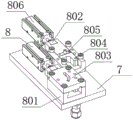
FIG. 4 is a schematic structural view of the screw distributor of the present invention;
fig. 5 is a schematic structural view of the fixing frame of the present invention;
fig. 6 is a schematic structural view of the driving mechanism of the present invention;
fig. 7 is a schematic structural view of the upper pneumatic mechanism of the present invention;
fig. 8 is a schematic structural view of the lower pneumatic mechanism of the present invention;
FIG. 9 is a schematic structural view of the automatic screw clamp of the present invention;
fig. 10 is a schematic structural diagram of the material rail mechanism of the present invention.
In the figure: 1-machine table, 101-machine frame, 102-platen, 103-door plate, 104-baffle, 105-adjustable cup foot, 2-support column frame, 3-screw placer, 4-first pipeline, 401-connector, 402-pipeline body, 5-left and right station mechanism, 6-second pipeline, 7-fixing plate, 8-screw distributor, 801-fixing piece, 802-feeding slide rail wedge, 803-feeding positioning slide rail, 804-feeding slide rail, 805-discharging frame, 806-slide rail cylinder, 9-fixing frame, 901-supporting plate, 902-vertical plate, 903-guide rail, 904-motor supporting plate, 10-driving mechanism, 1001-servo motor, 1002-coupler, 1003-universal connector and 1004-first electric batch clamping shaft, 1005-first bearing, 1006-bearing seat, 1007-second bearing, 1008-second electric batch clamp coupling, 1009-electric batch clamp, 1010-electric batch head, 11-upper pneumatic mechanism, 1101-upper cylinder, 1102-upper cylinder connecting piece, 1103-upper batch support column, 1104-electronic limiting plate, 1105-microswitch, 12-lower pneumatic mechanism, 1201-lower cylinder, 1202-lower cylinder connecting piece, 1203-lower electric batch support column, 13-screw automatic clamp, 1301-main clamp fixing plate, 1302-first main claw, 1303-second main claw, 14-material rail mechanism, 1401-material feeding cylinder, 1402-cylinder fixing frame, 1403-connecting frame, 1404-push rod, 1404-material feeding rail, 1406-material rail fixing plate, 1407-material rail fixing frame, 1408-rail clamp plate, 1409-rail, 1410-product, 1411-friction wedge press plate, 1412-discharge hopper.
Detailed Description
The invention will be further described with reference to the accompanying drawings, but the scope of the invention is not limited to the following description.
As shown in fig. 1-10, an automatic screw feeding machine comprises a machine table 1, wherein a support column frame 2 is fixedly installed at one end of the top of the machine table 1 through screws, a screw placing device 3 is fixedly installed at the top end of the support column frame 2 through screws, a first pipeline 4 is fixedly connected to the bottom of the screw placing device 3, a left station mechanism 5 and a right station mechanism 5 are fixedly connected to one end of the first pipeline 4, a second pipeline 6 is fixedly connected to one end of the left station mechanism 5 and one end of the second pipeline 6, which is far away from the left station mechanism 5 and the right station mechanism 5, are fixedly connected to the machine table 1; the machine table 1 comprises a rack 101, a table plate 102, a door plate 103, a baffle plate 104 and an adjustable cup foot 105, wherein the rack 101 is fixedly connected with the table plate 102, the table plate 102 is positioned at the top end of the rack 101, the middle part of the rack 101 is rotatably connected with the door plate 103, the two ends of the rack 101 are fixedly connected with the baffle plate 104, and the bottom of the rack 101 is fixedly connected with the adjustable cup foot 105; the screw placer 3 comprises a fixing plate 7 and a screw dividing device 8, the fixing plate 7 and the screw dividing device 8 are fixedly connected through screws, and the screw dividing device 8 is positioned at the top end of the fixing plate 7; the screw distributor 8 comprises a fixing piece 801, a feeding slide rail wedge 802, a feeding positioning slide rail 803, a feeding slide rail 804, a discharging frame 805 and a slide rail cylinder 806, wherein the middle part of the fixing piece 801 is movably connected with the feeding slide rail 804, one end of the feeding slide rail 804 is clamped with the feeding slide rail wedge 802, the feeding slide rail wedge 802 is fixedly connected with the slide rail cylinder 806, the middle part of the feeding slide rail 804 is movably connected with the discharging frame 805, and the top end of the fixing piece 801 is fixedly provided with the feeding positioning slide rail 803 through a screw; the first pipeline 4 comprises a connector 401 and a pipeline body 402, and the connector 401 is fixedly connected to two ends of the pipeline body 402; the left and right station mechanisms 5 comprise a fixed frame 9, a driving mechanism 10, an upper pneumatic mechanism 11, a lower pneumatic mechanism 12, screw automatic clamps 13 and a material rail mechanism 14, the top end of the fixed frame 9 is fixedly connected with the driving mechanism 10, the tops of the two ends of the fixed frame 9 are fixedly connected with the upper pneumatic mechanism 11, the bottoms of the two ends of the fixed frame 9 are fixedly connected with the lower pneumatic mechanism 12, one end of the lower pneumatic mechanism 12 is fixedly provided with the screw automatic clamps 13 through screws, and the bottom of the fixed frame 9 is fixedly connected with the material rail mechanism 14; the fixing frame 9 comprises a supporting plate 901, a vertical plate 902, a guide rail 903 and a motor supporting plate 904, wherein the vertical plate 902 is fixedly installed at two ends of the top of the supporting plate 901 through screws, the guide rail 903 is fixedly connected to one end of the middle of the vertical plate 902, and the motor supporting plate 904 is fixedly installed at the top end of the vertical plate 902 through screws; the driving mechanism 10 comprises a servo motor 1001, a coupler 1002, a universal connector 1003, a first electric screwdriver clamp coupling 1004, a first bearing 1005, a bearing seat 1006, a second bearing 1007, a second electric screwdriver clamp coupling 1008, an electric screwdriver clamp 1009 and an electric screwdriver head 1010, wherein the coupler 1002 is fixedly installed on an output shaft of the servo motor 1001, the universal connector 1003 is fixedly installed at the bottom of the coupler 1002, the first electric screwdriver clamp coupling 1004 is rotatably connected to the bottom of the universal connector 1003, the first electric screwdriver clamp coupling 1004 is inserted into the first bearing 1005 in a transition fit manner, the first electric screwdriver clamp coupling 1004 is in transition fit with the first bearing 1005, the first bearing 1005 is rotatably connected with the bearing seat 1006, the first bearing 1005 is positioned at the top of the bearing seat 1006, the second bearing 1007 is rotatably connected to the bottom of the bearing seat 1006, the second electric screwdriver clamp coupling 1008 is fixedly installed inside the second bearing 1007, the second bearing 1007 is in transition fit with the second electric screwdriver clamp coupling 1008, the bottom of the second electric screwdriver coupling shaft 1008 is rotatably connected with an electric screwdriver clamp 1009, and the bottom of the electric screwdriver clamp 1009 is fixedly connected with an electric screwdriver head 1010; the upper pneumatic mechanism 11 comprises an upper cylinder 1101, an upper cylinder connecting piece 1102, an upper batch support 1103, an electronic limiting plate 1104 and a microswitch 1105, wherein the upper cylinder connecting piece 1102 is fixedly installed at the bottom of the upper cylinder 1101 through a screw, the upper cylinder 1101 is connected with the electronic limiting plate 1104 through a screw, the upper batch support 1103 is fixedly installed at the bottom of the upper cylinder connecting piece 1102 through a screw, the electronic limiting plate 1104 is positioned below the upper cylinder connecting piece 1102, the electronic limiting plate 1104 is connected with the upper batch support 1103 through a screw, and the microswitch 1105 is positioned at the bottom of the electronic limiting plate 1104; the lower pneumatic mechanism 12 comprises a lower cylinder 1201, a lower cylinder connecting piece 1202 and a lower electric screwdriver support 1203, wherein the top of the lower cylinder 1201 is fixedly provided with the lower cylinder connecting piece 1202 through a screw, and the top end of the lower cylinder connecting piece 1202 is fixedly provided with the lower electric screwdriver support 1203 through a screw; the screw automatic clamp 13 comprises a main clamp fixing plate 1301, a first main claw 1302 and a second main claw 1303, wherein the main clamp fixing plate 1301 is fixedly provided with the first main claw 1302 through screws, and one end of the first main claw 1302 is clamped with the second main claw 1303; the material rail mechanism 14 comprises a feeding cylinder 1401, a cylinder fixing frame 1402, a connecting frame 1403, a push rod 1404, a feeding rail 1405, a material rail fixing plate 1406, a material rail fixing frame 1407, a material rail clamping plate 1408, a material rail 1409, a product 1410, a friction wedge pressing plate 1411 and a material discharging hopper 1412, wherein one end of the feeding cylinder 1401 is fixedly connected with the cylinder fixing frame 1402 through a screw, the cylinder fixing frame 1402 is fixedly connected with the connecting frame 1403, the top end of the material rail fixing plate 1406 is fixedly provided with the feeding rail 1405 through a screw, the push rod 1404 is fixedly connected with the feeding cylinder 1405, the feeding rail 1405 is positioned at the top end of the connecting frame 1403, one end of the feeding rail 1405 is fixedly connected with the material rail fixing frame 1407, one end of the material rail fixing frame 1407 is fixedly provided with the material rail clamping plate 1408 through a screw, the middle part of the material rail fixing frame 1407 is inserted with the material rail 1409, the other end, the obliquely downward discharging hopper 1412 is positioned at the bottom of the feeding rail 1405, the product 1410 and the push rod 1404 are positioned at the middle part of the feeding rail 1405, the rack 101 and the door panel 103 are connected through a hinge, four corners of the bottom of the rack 101 are provided with fixing grooves matched with the adjustable cup legs 105, four adjustable cup legs 105 are provided, four adjustable cup legs 105 are respectively positioned at four corners of the rack 101, one end of the bedplate 102 is provided with a slotted hole matched with the second pipeline 6, the bottom of the support column frame 2 is provided with a through hole, the middle end of the bottom of the fixing plate 7 is provided with a fixing groove matched with the support column frame 2, the bottom of the fixing plate 7 is provided with a slotted hole matched with the first pipeline 4, one end of the fixing plate 7 is provided with a threaded hole, two screw separating devices 8 are provided, two screw separating devices 8 are adjacent, the middle part of the fixing element 801 is provided with a sliding groove matched, two ends of a feeding positioning slide rail 803 are provided with through holes, the middle part of the feeding positioning slide rail 803 is provided with an arc-shaped groove, one end of a feeding slide rail 804 is provided with a clamping groove matched with a feeding slide rail wedge 802, the top end of the feeding slide rail 804 is provided with a sliding groove matched with a discharging frame 805, two first pipelines 4 are provided, the two first pipelines 4 are respectively positioned at two ends of a left station mechanism 5 and a right station mechanism 5, a connector 401 at one end of a pipeline body 402 is fixed at the bottom of a fixed plate 7, the connector 401 at the other end of the pipeline body 402 is fixedly connected with an automatic screw clamp 13, the top end of a supporting plate 901 is provided with a groove matched with a vertical plate 902, the top end of the vertical plate 902 is provided with a threaded hole, the middle part of the vertical plate 902 is provided with a positioning groove matched with a guide rail 903, two ends of the, the servo motor 1001 is in transition fit with the coupling 1002, the universal connector 1003 is in transition fit with the first electric screwdriver chuck coupling 1004, the bearing seat 1006 is fixedly connected with the upper screwdriver support 1103 through screws, a slotted hole matched with the second electric screwdriver chuck coupling 1008 is formed in the top end of the electric screwdriver chuck 1009, a fixing groove matched with the screwdriver head 1010 is formed in the bottom of the electric screwdriver chuck 1009, through holes are formed in two ends of the upper cylinder connecting piece 1102, a threaded hole is formed in the top end of the upper screwdriver support 1103, a clamping groove matched with the guide rail 903 is formed in one end of the upper screwdriver support 1103, a positioning sliding groove is formed in one end of the electronic limiting plate 1104, the microswitch 1105 is fixed with the vertical plate 902 through screws, slotted holes are formed in two ends of the lower cylinder connecting piece 1202, a threaded hole is formed in the bottom of the lower screwdriver support 1203, a clamping groove matched with the guide rail 903 is formed in one end of, the draw-in groove with first main claw 1302 looks adaptation is seted up to the one end of main clamp fixed plate 1301, the notch with second main claw 1303 looks adaptation is seted up to the one end of first main claw 1302, the notch of slope is seted up to the inside of first main claw 1302, material rail mechanism 14 is located the below that the screw presss from both sides 13 automatically, the slotted hole has been seted up to the one end of cylinder mount 1402, the spout of push rod 1404 looks adaptation is seted up at the middle part of feeding track 1405, the recess with feeding track 1405 looks adaptation is seted up at the top of material rail fixed plate 1406.
The working process of the utility model is as follows: when the automatic screw feeding machine is used, a user places screws on the top end of a material placing frame 805 through an arc-shaped groove in the middle of a feeding positioning slide rail 803, pushes a feeding slide rail wedge 802 through a slide rail air cylinder 806, and enables the feeding slide rail wedge 802 to push a feeding slide rail 804 to move, so that the screws on the top end of the material placing frame 805 slide along the arc-shaped groove of the feeding positioning slide rail 803, the screws on the top end of the material placing frame 805 drive the material placing frame 805 to move along a sliding groove of the feeding slide rail 804, the screws are conveyed to the upper part of one end of a first pipeline 4, the screws are moved to a screw automatic clamp 13 through the first pipeline 4, the screws can be effectively and automatically conveyed, the time for mounting the screws in a stopping mode is avoided, the efficiency of screw mounting is improved, the automatic screw feeding machine conveys products into the sliding groove of a feeding rail 1405 through a material rail 1409, and the screws and products in the screw, by controlling the upper pneumatic mechanism 11 and the lower pneumatic mechanism 12, the upper pneumatic mechanism 11 and the lower pneumatic mechanism 12 drive the screw automatic clamp 13 to move up and down, the feeding cylinder 1401 drives the push rod 1404 to move, the push rod 1404 pushes the product 1410 to move, the screw automatic clamp 13 is enabled to mount the products one by one, and then the screws can be effectively mounted by replacing manual operation, the time of manual operation is saved, and the efficiency of screw mounting is improved.
Although embodiments of the present invention have been shown and described, it will be appreciated by those skilled in the art that changes, modifications, substitutions and alterations can be made in these embodiments without departing from the principles and spirit of the invention, the scope of which is defined in the appended claims and their equivalents.
Claims (10)
1. The utility model provides an automatic go up screw machine, includes board (1), its characterized in that: a support column frame (2) is fixedly arranged at one end of the top of the machine table (1) through screws, a screw placer (3) is fixedly arranged at the top end of the support column frame (2) through screws, a first pipeline (4) is fixedly connected to the bottom of the screw placer (3), a left station mechanism and a right station mechanism (5) are fixedly connected to one end of the first pipeline (4), a second pipeline (6) is fixedly connected to one end of the left station mechanism and the right station mechanism (5), and one end, far away from the left station mechanism and the right station mechanism (5), of the second pipeline (6) is fixedly connected with the machine table (1);
the machine table (1) comprises a rack (101), a table plate (102), a door plate (103), a baffle plate (104) and an adjustable cup foot (105), wherein the rack (101) is fixedly connected with the table plate (102), the table plate (102) is positioned at the top end of the rack (101), the door plate (103) is rotatably connected to the middle of the rack (101), the baffle plate (104) is fixedly connected to two ends of the rack (101), and the adjustable cup foot (105) is fixedly connected to the bottom of the rack (101);
the screw placer (3) comprises a fixing plate (7) and a screw dividing device (8), the fixing plate (7) and the screw dividing device (8) are fixedly connected through screws, and the screw dividing device (8) is positioned at the top end of the fixing plate (7);
the screw distributor (8) comprises a fixing piece (801), a feeding slide rail wedge (802), a feeding positioning slide rail (803), a feeding slide rail (804), a material discharging frame (805) and a slide rail cylinder (806), wherein the middle part of the fixing piece (801) is movably connected with the feeding slide rail (804), one end of the feeding slide rail (804) is clamped with the feeding slide rail wedge (802), the feeding slide rail wedge (802) is fixedly connected with the slide rail cylinder (806), the middle part of the feeding slide rail (804) is movably connected with the material discharging frame (805), and the top end of the fixing piece (801) is fixedly provided with the feeding positioning slide rail (803) through a screw;
the first pipeline (4) comprises a connector (401) and a pipeline body (402), and the two ends of the pipeline body (402) are fixedly connected with the connectors (401);
the left station mechanism and the right station mechanism (5) comprise a fixed frame (9), a driving mechanism (10), an upper pneumatic mechanism (11), a lower pneumatic mechanism (12), screw automatic clamps (13) and a material rail mechanism (14), the driving mechanism (10) is fixedly connected to the top end of the fixed frame (9), the upper pneumatic mechanism (11) is fixedly connected to the tops of the two ends of the fixed frame (9), the lower pneumatic mechanism (12) is fixedly connected to the bottoms of the two ends of the fixed frame (9), the screw automatic clamps (13) are fixedly mounted at one end of the lower pneumatic mechanism (12) through screws, and the material rail mechanism (14) is fixedly connected to the bottom of the fixed frame (9);
the fixing frame (9) comprises a supporting plate (901), a vertical plate (902), a guide rail (903) and a motor supporting plate (904), the vertical plate (902) is fixedly installed at two ends of the top of the supporting plate (901) through screws, the guide rail (903) is fixedly connected to one end of the middle of the vertical plate (902), and the motor supporting plate (904) is fixedly installed at the top end of the vertical plate (902) through screws;
the driving mechanism (10) comprises a servo motor (1001), a coupler (1002), a universal connector (1003), a first electric screwdriver clamp coupling (1004), a first bearing (1005), a bearing seat (1006), a second bearing (1007), a second electric screwdriver clamp coupling (1008), an electric screwdriver clamp (1009) and an electric screwdriver head (1010), wherein the coupler (1002) is fixedly installed on an output shaft of the servo motor (1001), the universal connector (1003) is fixedly installed at the bottom of the coupler (1002), the first electric screwdriver clamp coupling (1004) is rotatably connected to the bottom of the universal connector (1003), the first electric screwdriver clamp coupling (1004) is inserted into the first bearing (1005), transition fit is formed between the first electric screwdriver clamp coupling (1004) and the first bearing (1005), the first bearing (1005) is rotatably connected with the bearing seat (1006), and the first bearing (1005) is located at the top of the bearing seat (1006), the bottom of the bearing seat (1006) is rotatably connected with a second bearing (1007), a second electric screwdriver connecting shaft (1008) is fixedly installed inside the second bearing (1007), transition fit is formed between the second bearing (1007) and the second electric screwdriver connecting shaft (1008), the bottom of the second electric screwdriver connecting shaft (1008) is rotatably connected with an electric screwdriver clamp (1009), and the bottom of the electric screwdriver clamp (1009) is fixedly connected with an electric screwdriver head (1010);
the upper pneumatic mechanism (11) comprises an upper air cylinder (1101), an upper air cylinder connecting piece (1102), an upper screwdriver support column (1103), an electronic limiting plate (1104) and a microswitch (1105), wherein the upper air cylinder connecting piece (1102) is fixedly installed at the bottom of the upper air cylinder (1101) through a screw, the upper air cylinder (1101) is connected with the electronic limiting plate (1104) through a screw, the upper screwdriver support column (1103) is fixedly installed at the bottom of the upper air cylinder connecting piece (1102) through a screw, the electronic limiting plate (1104) is located below the upper air cylinder connecting piece (1102), the electronic limiting plate (1104) is connected with the upper screwdriver support column (1103) through a screw, and the microswitch (1105) is located at the bottom of the electronic limiting plate (1104);
the lower pneumatic mechanism (12) comprises a lower cylinder (1201), a lower cylinder connecting piece (1202) and a lower electric screwdriver support column (1203), wherein the top of the lower cylinder (1201) is fixedly provided with the lower cylinder connecting piece (1202) through a screw, and the top end of the lower cylinder connecting piece (1202) is fixedly provided with the lower electric screwdriver support column (1203) through a screw;
the automatic screw clamp (13) comprises a main clamp fixing plate (1301), a first main claw (1302) and a second main claw (1303), wherein the first main claw (1302) is fixedly installed on the main clamp fixing plate (1301) through a screw, and the second main claw (1303) is clamped at one end of the first main claw (1302);
the material rail mechanism (14) comprises a feeding cylinder (1401), a cylinder fixing frame (1402), a connecting frame (1403), a push rod (1404), a feeding rail (1405), a material rail fixing plate (1406), a material rail fixing frame (1407), a material rail clamping plate (1408), a material rail (1409), a product (1410), a friction wedge pressing plate (1411) and a discharging hopper (1412), wherein one end of the feeding cylinder (1401) is fixedly connected with the cylinder fixing frame (1402) through a screw, the cylinder fixing frame (1402) is fixedly connected with the connecting frame (1403), the top end of the material rail fixing plate (1406) is fixedly provided with the feeding rail (1405) through a screw, the push rod (1404) is fixedly connected with the feeding cylinder (1401), the feeding rail (1405) is positioned at the top end of the connecting frame (1403), one end of the feeding rail (1405) is fixedly connected with the material rail fixing frame (1407), one end of the material rail fixing frame (1407) is fixedly provided with the material rail clamping plate (1408, the middle part of material rail mount (1407) is pegged graft and is had material rail (1409), there is friction wedge clamp plate (1411) at the other end of feeding track (1405) through screw fixed mounting, it is downward to set up to slope out hopper (1412), the downward play hopper (1412) that inclines is located the bottom of feeding track (1405), product (1410) and push rod (1404) are located the middle part of feeding track (1405).
2. An automatic screwing machine according to claim 1, characterized in that: the adjustable cup stand is characterized in that the rack (101) is connected with the door panel (103) through hinges, four corners of the bottom of the rack (101) are provided with fixing grooves matched with the adjustable cup stands (105), the number of the adjustable cup stands (105) is four, the four adjustable cup stands (105) are respectively located at the four corners of the rack (101), one end of the bedplate (102) is provided with a groove hole matched with the second pipeline (6), and the bottom of the support column frame (2) is provided with a through hole.
3. An automatic screwing machine according to claim 1, characterized in that: the middle end of the bottom of the fixing plate (7) is provided with a fixing groove matched with the support column frame (2), the bottom end of the fixing plate (7) is provided with a slotted hole matched with the first pipeline (4), and one end of the fixing plate (7) is provided with a threaded hole.
4. An automatic screwing machine according to claim 1, characterized in that: the screw dividing device is characterized in that the number of the screw dividing devices (8) is two, the screw dividing devices (8) are adjacent, sliding grooves matched with the feeding sliding rails (804) are formed in the middle of the fixing piece (801), threaded holes are formed in the top end of the fixing piece (801), through holes are formed in two ends of the feeding positioning sliding rails (803), arc-shaped grooves are formed in the middle of the feeding positioning sliding rails (803), clamping grooves matched with the feeding sliding rail wedges (802) are formed in one ends of the feeding sliding rails (804), and sliding grooves matched with the discharging frames (805) are formed in the top end of the feeding sliding rails (804).
5. An automatic screwing machine according to claim 1, characterized in that: first pipeline (4) have two, two station mechanism (5) both ends about first pipeline (4) are located respectively, the bottom of fixed plate (7) is fixed in connector (401) of the pipeline body (402) one end, connector (401) and the automatic clamp of screw (13) fixed connection of the pipeline body (402) other end.
6. An automatic screwing machine according to claim 1, characterized in that: the top end of the supporting plate (901) is provided with a groove matched with the vertical plate (902), the top end of the vertical plate (902) is provided with a threaded hole, the middle part of the vertical plate (902) is provided with a positioning groove matched with the guide rail (903), two ends of the vertical plate (902) are provided with sliding grooves, four corners of the motor supporting plate (904) are provided with through holes, and the middle part of the motor supporting plate (904) is provided with a fixing groove matched with the servo motor (1001).
7. An automatic screwing machine according to claim 1, characterized in that: for transition fit between servo motor (1001) and shaft coupling (1002), be transition fit between universal connector (1003) and the first electricity batch clip coupling (1004), bearing frame (1006) and last batch pillar (1103) pass through screw fixed connection, the slotted hole of pressing from both sides coupling (1008) looks adaptation is seted up with the second electricity batch to the top that presss from both sides (1009) in the electricity batch, the fixed slot of pressing from both sides head (1010) looks adaptation is seted up and electricity batch to the bottom that presss from both sides (1009) in the electricity batch.
8. An automatic screwing machine according to claim 1, characterized in that: the improved electric screwdriver is characterized in that through holes are formed in two ends of the upper cylinder connecting piece (1102), a threaded hole is formed in the top end of the upper screwdriver support (1103), a clamping groove matched with the guide rail (903) is formed in one end of the upper screwdriver support (1103), a positioning sliding groove is formed in one end of the electronic limiting plate (1104), the micro switch (1105) is fixed with the vertical plate (902) through screws, slotted holes are formed in two ends of the lower cylinder connecting piece (1202), a threaded hole is formed in the bottom of the lower screwdriver support (1203), and a clamping groove matched with the guide rail (903) is formed in one end of the lower screwdriver support (1203).
9. An automatic screwing machine according to claim 1, characterized in that: one end of the main clamp fixing plate (1301) is provided with a clamping groove matched with the first main claw (1302), one end of the first main claw (1302) is provided with a notch matched with the second main claw (1303), and the first main claw (1302) is internally provided with an inclined notch.
10. An automatic screwing machine according to claim 1, characterized in that: the material rail mechanism (14) is located below the screw automatic clamp (13), a slotted hole is formed in one end of the air cylinder fixing frame (1402), a sliding groove matched with the push rod (1404) is formed in the middle of the feeding track (1405), and a groove matched with the feeding track (1405) is formed in the top end of the material rail fixing plate (1406).
Priority Applications (1)
| Application Number | Priority Date | Filing Date | Title |
|---|---|---|---|
| CN202021446647.4U CN212683080U (en) | 2020-07-21 | 2020-07-21 | Automatic screw feeding machine |
Applications Claiming Priority (1)
| Application Number | Priority Date | Filing Date | Title |
|---|---|---|---|
| CN202021446647.4U CN212683080U (en) | 2020-07-21 | 2020-07-21 | Automatic screw feeding machine |
Publications (1)
| Publication Number | Publication Date |
|---|---|
| CN212683080U true CN212683080U (en) | 2021-03-12 |
Family
ID=74898444
Family Applications (1)
| Application Number | Title | Priority Date | Filing Date |
|---|---|---|---|
| CN202021446647.4U Active CN212683080U (en) | 2020-07-21 | 2020-07-21 | Automatic screw feeding machine |
Country Status (1)
| Country | Link |
|---|---|
| CN (1) | CN212683080U (en) |
Cited By (1)
| Publication number | Priority date | Publication date | Assignee | Title |
|---|---|---|---|---|
| CN116329914A (en) * | 2023-05-15 | 2023-06-27 | 安徽百信信息技术有限公司 | Self-holding screw locking machine feeding device |
-
2020
- 2020-07-21 CN CN202021446647.4U patent/CN212683080U/en active Active
Cited By (1)
| Publication number | Priority date | Publication date | Assignee | Title |
|---|---|---|---|---|
| CN116329914A (en) * | 2023-05-15 | 2023-06-27 | 安徽百信信息技术有限公司 | Self-holding screw locking machine feeding device |
Similar Documents
| Publication | Publication Date | Title |
|---|---|---|
| CN212683080U (en) | Automatic screw feeding machine | |
| CN209102509U (en) | A kind of frock clamp of high temperature and humidity temperature shock test box | |
| CN212070443U (en) | An adjustable workpiece clamping device for a radial drilling machine | |
| CN210306630U (en) | Gas valve assembly equipment | |
| WO2018145437A1 (en) | Automatic nut screwing device for door frame guide rail | |
| CN215746557U (en) | Special-shaped part clamping tool with high-precision drilling function | |
| CN111015293A (en) | Workpiece clamping and adjusting mechanism of machining tool | |
| CN207057770U (en) | A kind of automatic tapping machine | |
| CN218361760U (en) | Stamping device for automobile parts suitable for not unidimensional processing | |
| CN217071471U (en) | Drilling and chamfering integrated equipment | |
| CN106311952B (en) | Automatic nut riveting machine | |
| CN216632902U (en) | Nut tapping machine | |
| CN216544800U (en) | Automatic processing device for injection molding piece | |
| CN210413376U (en) | Automatic assembling machine for lampshade of electric welding pliers | |
| CN211804590U (en) | Welding fixture for automobile rear end plate and side wall plate | |
| CN220805723U (en) | Chamfering device for mechanical accessory production | |
| CN219746557U (en) | Tapping device for nut production | |
| CN208895624U (en) | A kind of milling boring equipment can be used for oblique surface machining | |
| CN223802438U (en) | A fixture for an easily adjustable automated production line | |
| CN216463102U (en) | Side clamping device for machining plate parts | |
| CN222243559U (en) | A grounding frame assembly machine | |
| CN222037530U (en) | A mechanical parts maintenance device that is easy to maintain | |
| CN212946433U (en) | Automatic screw feeding device for notebook computer | |
| CN217019422U (en) | Electronic product processing device of precise numerical control machine tool | |
| CN220260769U (en) | Jig convenient to stack |
Legal Events
| Date | Code | Title | Description |
|---|---|---|---|
| GR01 | Patent grant | ||
| GR01 | Patent grant |