CN212824924U - Carrier tool - Google Patents
Carrier tool Download PDFInfo
- Publication number
- CN212824924U CN212824924U CN202021450591.XU CN202021450591U CN212824924U CN 212824924 U CN212824924 U CN 212824924U CN 202021450591 U CN202021450591 U CN 202021450591U CN 212824924 U CN212824924 U CN 212824924U
- Authority
- CN
- China
- Prior art keywords
- hole
- pressing
- block
- product
- base
- Prior art date
- Legal status (The legal status is an assumption and is not a legal conclusion. Google has not performed a legal analysis and makes no representation as to the accuracy of the status listed.)
- Active
Links
- 238000001125 extrusion Methods 0.000 claims abstract description 52
- 230000000149 penetrating effect Effects 0.000 claims description 10
- 238000004891 communication Methods 0.000 claims description 2
- 238000006243 chemical reaction Methods 0.000 abstract description 7
- 238000000034 method Methods 0.000 description 10
- 102100038804 FK506-binding protein-like Human genes 0.000 description 6
- 101001031402 Homo sapiens FK506-binding protein-like Proteins 0.000 description 6
- 101100443272 Arabidopsis thaliana DIR2 gene Proteins 0.000 description 5
- 230000008569 process Effects 0.000 description 5
- XEEYBQQBJWHFJM-UHFFFAOYSA-N Iron Chemical compound [Fe] XEEYBQQBJWHFJM-UHFFFAOYSA-N 0.000 description 4
- 238000010586 diagram Methods 0.000 description 3
- 238000012545 processing Methods 0.000 description 3
- 229910052742 iron Inorganic materials 0.000 description 2
- 230000004048 modification Effects 0.000 description 2
- 238000012986 modification Methods 0.000 description 2
- 238000010521 absorption reaction Methods 0.000 description 1
- 230000009471 action Effects 0.000 description 1
- 239000000853 adhesive Substances 0.000 description 1
- 230000001070 adhesive effect Effects 0.000 description 1
- 230000006835 compression Effects 0.000 description 1
- 238000007906 compression Methods 0.000 description 1
- 230000007547 defect Effects 0.000 description 1
- 238000006073 displacement reaction Methods 0.000 description 1
- 229920006351 engineering plastic Polymers 0.000 description 1
- 230000006872 improvement Effects 0.000 description 1
- 238000012994 industrial processing Methods 0.000 description 1
- 239000000463 material Substances 0.000 description 1
- 238000000465 moulding Methods 0.000 description 1
- 230000003068 static effect Effects 0.000 description 1
- 230000007306 turnover Effects 0.000 description 1
- 238000003466 welding Methods 0.000 description 1
Images




Landscapes
- Press Drives And Press Lines (AREA)
Abstract
The embodiment of the utility model discloses carrier, including base, stopper, clamp plate and ejector pad, stopper and base fixed connection have along the extrusion hole that the first direction runs through, and the clamp plate rotationally is connected with the base and has and be used for compressing tightly the product in the end that compresses tightly of base, and the ejector pad has the extrusion piece that corresponds with the extrusion hole with the movably connection of clamp plate and one end. By moving the extrusion block to the extrusion hole, the extrusion hole generates a reaction force against the extrusion block opposite to the pressing plate, so that the pressing plate can press the product. Therefore, the utility model discloses the shortcoming of the easy damage product of conventional upset clamp plate formula carrier can be overcome to the carrier, improves the yields of product to simple structure, convenient to use.
Description
Technical Field
The utility model relates to an industrial processing equipment technical field, concretely relates to carrier.
Background
In the process of product processing, in order to ensure the stability of the product in the processing process, a carrier is needed to position the product. The upset clamp plate carrier is one of them carrier commonly used, and current upset clamp plate carrier uses the mode of magnet absorption to make the clamp plate compress tightly the product usually, because magnet suction can make the clamp plate produce great speed at the in-process of upset clamp plate whereabouts, injures the product by a crashing object easily, reduces the yields of product.
SUMMERY OF THE UTILITY MODEL
In view of this, the embodiment of the utility model provides a carrier can solve the uncontrollable problem of clamp plate falling speed that adopts the magnet actuation to produce.
The utility model discloses carrier, include:
a base for carrying a product;
the limiting block is fixedly connected with the base and is provided with an extrusion hole penetrating along a first direction;
the pressing plate is rotatably connected with the base and provided with a first through hole and a pressing end, the first through hole can be penetrated by the limiting block, the shape of the pressing end corresponds to that of the product, and the pressing end is configured to press the product to the base; and
the pushing block is movably connected with the pressing plate, and one end of the pushing block is provided with an extrusion block corresponding to the extrusion hole.
Preferably, the extrusion blocks are wedge-shaped blocks.
Preferably, the carrier further comprises a handle, and the handle is connected with the pressing plate and/or the pushing block.
Preferably, the handle is rotatably connected to the pressing plate, the handle has a rotating shaft extending along a second direction, a strip-shaped guide hole penetrating along the second direction, and a guide pin penetrating through the guide hole, the second direction is perpendicular to the first direction, the guide pin is fixedly connected to the pushing block, and the guide pin is configured to move along the guide hole.
Preferably, the pushing block is further provided with a second through hole, the second through hole is intersected with the guide pin, and the handle is arranged in the second through hole in a penetrating mode.
Preferably, the pressure plate further has a third aperture, the third aperture being in communication with the second aperture, the handle further being configured to at least partially pass through the third aperture.
Preferably, the pressing plate is a magnetic pressing plate, and the carrier further comprises at least one magnet, wherein the magnet is fixedly connected with the push block.
Preferably, the expression block is configured to be within the expression aperture when moved to a wedged position and to be clear of the expression aperture when moved to a remote position;
when the pressing plate rotates to the pressing position, the pressing end presses the product on the base, and the limiting block penetrates through the first through hole.
Preferably, the pressing plate further has a guide groove extending in the first direction, and the pushing block is configured to move along the guide groove; the pressure plate is also configured to have a predetermined clearance with the end surface of the base when rotated to the pressing position.
Preferably, the base has a positioning slot for placing a product, the positioning slot having a shape corresponding to the product.
The utility model discloses carrier includes base, stopper, clamp plate and ejector pad, stopper and base fixed connection and have along the extrusion hole that the first direction runs through, and the clamp plate rotationally is connected with the base and has and be used for compressing tightly the product in the end that compresses tightly of base, and the ejector pad has the extrusion piece that corresponds with the extrusion hole with the movably connection of clamp plate and one end. By moving the extrusion block to the extrusion hole, the extrusion hole generates a reaction force against the extrusion block opposite to the pressing plate, so that the pressing plate can press the product. Therefore, the utility model discloses the shortcoming of the easy damage product of conventional upset clamp plate formula carrier can be overcome to the carrier, improves the yields of product to simple structure, convenient to use.
Drawings
The above and other objects, features and advantages of the present invention will become more apparent from the following description of the embodiments of the present invention with reference to the accompanying drawings, in which:
fig. 1 is a schematic perspective view of a carrier according to an embodiment of the present invention;
fig. 2 is a front view of a carrier according to an embodiment of the present invention;
fig. 3 is a top view of a carrier according to an embodiment of the present invention;
fig. 4 is a cross-sectional view of a carrier according to an embodiment of the present invention;
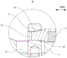
fig. 5 is a schematic structural diagram of a first extrusion block and extrusion holes according to an embodiment of the present invention;
fig. 6 is a schematic structural diagram of a second extrusion block and extrusion holes according to an embodiment of the present invention;
FIG. 7 is a schematic structural diagram of a third extrusion block and extrusion holes according to an embodiment of the present invention;
fig. 8 is a schematic view illustrating an opened state of the carrier according to an embodiment of the present invention;
fig. 9 is a schematic view of a working process of the carrier according to an embodiment of the present invention.
Description of reference numerals:
DIR 1-first direction; DIR 2-second direction; 1-a base; 11-a positioning groove; 2, a limiting block; 21-extruding holes; 3, pressing a plate; 31-a first perforation; 32-a compression end; 33-third perforations; 34-a guide groove; 4-pushing the block; 41-an extrusion block; 42-a second perforation; 43-step; 5-a handle; 51-a rotating shaft; 52-a pilot hole; 53-guide pins; 6-a magnet; 7-products; 71-a platform; 72-thread segment.
Detailed Description
The present invention will be described below based on examples, but the present invention is not limited to only these examples. In the following detailed description of the present invention, certain specific details are set forth in detail. It will be apparent to those skilled in the art that the present invention may be practiced without these specific details. Well-known methods, procedures, components and circuits have not been described in detail so as not to obscure the present invention.
Further, those of ordinary skill in the art will appreciate that the drawings provided herein are for illustrative purposes and are not necessarily drawn to scale.
Unless the context clearly requires otherwise, throughout the description, the words "comprise", "comprising", and the like are to be construed in an inclusive sense as opposed to an exclusive or exhaustive sense; that is, what is meant is "including, but not limited to".
In the description of the present invention, it is to be understood that the terms "first," "second," and the like are used for descriptive purposes only and are not to be construed as indicating or implying relative importance. In addition, in the description of the present invention, "a plurality" means two or more unless otherwise specified.
Fig. 1 to 3 are a schematic perspective view, a front view and a top view of the carrier of the present embodiment, respectively, and fig. 4 is a cross-sectional view taken along a direction a-a of fig. 3. As shown in fig. 1-4, the carrier of the present embodiment includes a base 1, a limiting block 2, a pressing plate 3 and a pushing block 4. The base 1 is used for bearing a product 7, and the limiting block 2 is fixedly connected with the base 1 and is provided with an extrusion hole 21 penetrating along a first direction DIR 1. Along with the rotatable connection with the base 1, the pressure plate 3 has a first through hole 31 and a pressing end 32, and the first through hole 31 is large enough and positioned for the stopper 2 to pass through. The pressing end 32 is used for pressing the product 7 onto the base 1, and the shape of the pressing end 32 corresponds to the shape of the product 7. The pushing block 4 is movably connected with the pressing plate 3, one end of the pushing block 4 is provided with a pressing block 41 corresponding to the pressing hole 21, and the relative position of the pressing end 32 and the product 7 and the pressure applied to the product 7 can be adjusted by controlling the position of the pressing block 41 in the pressing hole 21.
Preferably, the base 1 has a positioning slot 11 for placing the product 7, the shape of the positioning slot 11 corresponds to the shape of the product 7, for example, the lower end of the product 7 is substantially rectangular, the shape of the positioning slot 11 can also be substantially rectangular, and the size of the positioning slot 11 is adapted to the size of the product 7, so as to position the product 7.
In an alternative embodiment, the base 1 includes a positioning block, and the positioning block is detachably connected to the base 1 body, for example, by using screws, snaps, and the like. The locating slot 11 sets up on the locating piece, and the locating piece that has corresponding locating slot 11 is changed to the concrete product that can press as required from this, makes the carrier can be applicable to different products.
The limiting block 2 is fixedly connected with the base 1 and is spaced from the positioning groove 11 by a preset distance. The limiting block 2 is provided with a squeezing hole 21 penetrating along a first direction DIR1, the first direction DIR1 is substantially perpendicular to the direction in which the product 7 is pressed and held by the pressure plate 3 (i.e. the direction perpendicular to the positioning slot 11), i.e. the first direction DIR1 can be a direction parallel to the bottom surface of the positioning slot 11.
One end of the push block 4 opposite to the limiting block 2 is provided with a squeezing block 41 corresponding to the squeezing hole 21, one side of the squeezing hole 21 far away from the pressure plate 3 is provided with a first squeezing surface inclined to the pressing direction of the pressure plate 3, and one side of the squeezing block 41 opposite to the first squeezing surface is provided with a second squeezing surface, so that when the push block 4 moves along the first direction DIR1, the reaction force of the squeezing hole 21 on the squeezing block 41 has a component parallel to the pressing direction of the pressure plate 3, and the squeezing block 41 transmits corresponding pressing force to the product 7 through the pressure plate 3.
Fig. 5 to 7 are schematic views of structures of three kinds of extrusion blocks and extrusion holes of the present embodiment, and fig. 5 to 7 are enlarged partial views at B in fig. 4. As shown in fig. 5-7, the pressing block 41 of this embodiment may be a wedge-shaped block, and the wedge shape in this application refers to a region on the object having a cross section gradually shrinking along the axial direction of the object. The surface of the constricted region of the wedge block (i.e. the second pressing surface) may be a bevel (as shown in fig. 5 and 6), or may be a cambered surface (as shown in fig. 7), or, of course, may be a surface of another shape. The pressing hole 21 corresponds to the pressing block 41, the first pressing surface of the pressing hole 21 may be an inclined surface (as shown in fig. 5 and 7) or an arc surface (as shown in fig. 6), and the first pressing surface gradually inclines towards the plane where the positioning groove 11 is located in the direction away from the pressing block 41. The first extrusion surface and the second extrusion surface in fig. 5 are inclined surfaces with substantially the same slope, so that the extrusion hole 21 and the extrusion block 41 are in surface contact during extrusion, the acting force of the extrusion hole 21 and the extrusion block 41 can be uniformly distributed on a larger surface, the loss of the extrusion hole 21 or the extrusion block 41 due to stress concentration is avoided, and the processing is facilitated. Of course, the first pressing surface and the second pressing surface may be provided such that one is a curved surface and the other is an inclined surface, for example, the first pressing surface of the pressing hole 21 in fig. 6 is a curved surface and the second pressing surface of the pressing block 41 is an inclined surface, and the first pressing surface of the pressing hole 21 in fig. 7 is an inclined surface and the second pressing surface of the pressing block 41 is a curved surface. Alternatively, both the first extrusion surface and the second extrusion surface may be cambered surfaces.
Preferably, as shown in fig. 5 to 7, a step 43 is formed at the junction of the pressing block 41 and the pressing block body, that is, the contact surface of the pressing block body with the pressing plate 3 is more deviated from the axis of the pressing block 4 than the contact surface of the pressing block 41 with the bottom of the pressing hole 21. Therefore, the pushing block 4 can be prevented from being in good contact with the pressing plate 3 to transmit acting force when the extrusion block 41 is in the wedging position after the pushing block body moves and rubs on the pressing plate 3 to cause loss.
As shown in fig. 1 to 4, the pushing block 4 is movably connected to the pressing plate 3, for example, by providing a guide rail on the pressing plate 3, the pushing block 4 is connected to the slider, and the slider is moved along the guide rail. In the present embodiment, the side of the pressing plate 3 in contact with the pushing block 4 has a guide groove 34 extending in the first direction DIR1, the width of the guide groove 34 is adapted to the width of the pushing block 4, and the pushing block 4 can move along the guide groove 34. When the pressing plate 3 is in the pressing position, the guide groove 34 extends in the direction of the pressing hole 21 so that the push block 4 is aligned with the pressing hole 21.
Preferably, the carrier further includes a magnet 6, and the magnet 6 is fixedly connected to the push block 4, for example, a mounting hole matching with the shape of the magnet 6 may be formed on the push block 4, and the magnet 6 is snapped into the mounting hole by interference fit or fixed in the mounting hole by an adhesive, a screw, or the like. Of course, the push block 4 may be formed by wrapping a material such as engineering plastic around the magnet 6 by insert molding. The pressing plate 3 is a magnetic pressing plate, and the magnetic property in the present application refers to the property of an object being attracted by a magnet. For example, the pressing plate 3 may be made of iron, or an iron piece may be fixed to a side of the pressing plate 3 contacting the push block 4. Through magnet 6 and clamp plate 3 actuation mutually, can make magnet 6 can remove along clamp plate 3, prevent that push block 4 from dropping at the in-process that clamp plate 3 overturns, can make this reaction force can better transmit to clamp plate 3 on through the contact surface of push block 4 with clamp plate 3 when extrusion hole 21 produces the reaction force to extrusion block 41 simultaneously. Optionally, two ends of the push block 4 are respectively fixed with a magnet 6, so that the contact between the push block 4 and the press plate 3 can be more stable.
The pressure plate 3 is rotatably connected to the base 1 and can rotate relative to the base 1. For example, the base 1 may be provided with a support and a rotating shaft fixed to the support, and one end of the pressing plate 3 may be connected to the rotating shaft and may rotate around the rotating shaft. The platen 3 has a rotational axis substantially parallel to the base 1, and when the platen 3 is rotated to the compacting position, the compacting end 32 is opposite the detents 11, thereby securing the products 7 in the detents 11 from two opposite directions. Preferably, when the pressing plate 3 rotates to the pressing position, a preset gap is formed between the pressing plate and the upper end face of the base 1, and enough moving space can be provided for the pressing plate 3 to adapt to products 7 with different heights so as to press the products 7.
The shape of the compacting end 32 may correspond to the shape of the product 7. For example, the upper end of the product 7 illustrated in the present embodiment has a platform 71 and a cylindrical threaded section 72 connected to the platform 71, and the pressing end 32 has an arc-shaped surface matched to the threaded section 72, and when the pressing plate 3 is rotated to the pressing position, the end surface of the pressing end 32 contacts the platform 71, and the arc-shaped surface is opposite to the threaded section 72. The side of product 7 can be fixed a position to the arcwall face, prevents that product 7 from taking place to empty. The pressing end 32 and the body of the pressing plate 3 can be positioned in two mutually parallel planes with a predetermined distance, namely, the plane where the pressing end 32 is positioned deviates from the rotating shaft of the pressing plate 3, therefore, compared with the arrangement that the plane where the pressing end 32 is positioned is aligned with the rotating shaft of the pressing plate 3, the deviated pressing end 32 is longer in distance from the rotating shaft of the pressing plate 3, and the distance moved when the pressing plate 3 rotates is larger, so that the action of the pressing hole 21 on the pressing block 41 and the pressing plate 3 can be fully amplified.
Fig. 8 is a schematic view of an opened state of the vehicle of the present embodiment. As shown in FIG. 8, when the pressing plate 3 is opened, the pressing plate 3 and the pushing block 4 are far away from the positioning slot 11 and the limiting block 2. The pressing plate 3 is provided with a first through hole 31, the size of the first through hole 31 is matched with the size of the limiting block 2, and the width of the first through hole 31 is basically consistent with that of the limiting block 2. As shown in fig. 1-3, when the pressing plate 3 rotates to the pressing position, the stopper 2 passes through the first through hole 31, so as to guide the movement of the pressing plate 3 and prevent the pressing plate 3 from shaking.
Preferably, as shown in fig. 1-4 and 8, the carrier may further include a handle 5, and the handle 5 is connected to the pressing plate 3 and/or the pushing block 4, so that an operator can move the pressing plate 3 and/or the pushing block 4 through the handle 5.
In an alternative embodiment, the handle 5 is rotatably connected to the pressure plate 3. The handle 5 has a rotation shaft 51 extending in the second direction DIR2, a bar-shaped guide hole 52 penetrating the handle 5 in the second direction DIR2, and a guide pin 53 inserted in the bar-shaped guide hole 52. Wherein the second direction DIR2 is substantially perpendicular to the first direction DIR1 and the second direction DIR2 is substantially perpendicular to the length direction of the handle 5. The rotating shaft 51 is provided at one end of the handle 5 and connected to the pressing plate 3. The bar-shaped guide hole 52 is arranged in the middle section of the handle 5 and extends along the length direction of the handle 5, and the guide pin 53 is fixedly connected with the push block 4 and can move along the guide hole 52 on the handle 5, namely, the guide pin 53 can move along the length direction of the handle 5. The push block 4 has a second through hole 42, the pressure plate has a corresponding third through hole 33, the second through hole 42 and the third through hole 33 have widths through which the handle 5 can pass, and the second through hole 42 and the third through hole 33 can provide a predetermined range of movement space for the handle 5 on a plane perpendicular to the rotating shaft 51. The rotation shaft 51 of the handle 5 is disposed at the third through hole 33. Alternatively, after the guide pin 53 passes through the guide hole 52 in the second direction DIR2, both ends are connected to both side inner walls of the second through hole 42, respectively. I.e. the handle 5 is inserted through the second 42 and third 33 perforations. When the handle 5 is driven to rotate around the rotating shaft 51, the side wall of the strip-shaped guide hole 52 pushes the guide pin 53 and the push block 4 connected with the guide pin 53 to move along the pressure plate 3, in the process, the included angle between the handle 5 and the pressure plate 3 and the push block 4 is changed, the distance between the guide pin 53 and the rotating shaft 51 is changed, and the guide pin 53 moves along the guide hole 52 of the handle 5. The handle 5 forms a lever with a fulcrum as the rotating shaft 51, so that the pushing block 4 can be conveniently and laborsavingly driven to move, and the squeezing block 41 can be pushed into the squeezing hole 21 or the squeezing block 41 can be pushed out of the squeezing hole 21.
Fig. 9 is a schematic view of the operation process of the carrier of the present embodiment. The operation of the carrier of the present embodiment will be described with reference to fig. 8 and 9.
As shown in fig. 8, the platen 3 is rotated to a position away from the positioning groove 11, and the product 7 to be pressed is placed in the positioning groove 11 in a predetermined posture. The product 7 may be a whole or assembled by several parts, for example, if the carrier of the present embodiment is a welding carrier, several parts to be welded need to be assembled according to a predetermined assembly method and placed in the positioning groove 11. As shown in fig. 9, the pressing plate 3 is turned over so that the pressing end 32 contacts the product 7, and the stopper 2 is inserted into the first through hole 31 of the pressing plate 3. The handle 5 is pulled, so that the side wall of the guide hole 52 pushes the guide pin 53 and the push block 4 to move along the guide groove 34, and the squeezing block 41 enters the squeezing hole 21. The handle 5 is further shifted to enable the second squeezing surface of the squeezing block 41 to be in close contact with the first squeezing surface of the squeezing hole 21, the first squeezing surface generates a reaction force to the squeezing block 41, the pushing block 4 generates downward (downward in the figure) displacement, and the pressing plate 3 is pushed to enable the pressing end 32 to press the product 7. Since the pressing force between the pressing hole 21 and the pressing block 41 is large, the static friction force is also large, and the pressing block 41 is not easily separated from the pressing hole 21. When the product 7 needs to be taken out, the handle 5 is stirred clockwise in the figure by a certain acting force, so that the squeezing block 41 is separated from the squeezing hole 21, and then the pressing plate 3 is turned over, so that the product 7 can be taken out from the positioning groove 11.
The carrier of this embodiment includes base, stopper, clamp plate and ejector pad, stopper and base fixed connection and have along the extrusion hole that first direction runs through, and the clamp plate is rotationally connected with the base and has and be used for compressing tightly the product in the end that compresses tightly of base, and the ejector pad is connected with the clamp plate is movably and one end has the extrusion piece that corresponds with the extrusion hole. By moving the extrusion block to the extrusion hole, the extrusion hole generates a reaction force against the extrusion block opposite to the pressing plate, so that the pressing plate can press the product. Therefore, the carrier of the embodiment can overcome the defect that the conventional turnover pressing plate type carrier is easy to damage products, improves the yield of the products, and is simple in structure and convenient to use.
The above description is only a preferred embodiment of the present invention and is not intended to limit the present invention, and various modifications and changes may be made by those skilled in the art. Any modification, equivalent replacement, or improvement made within the spirit and principle of the present invention should be included within the protection scope of the present invention.
Claims (10)
1. A carrier, comprising:
a base for carrying a product;
the limiting block is fixedly connected with the base and is provided with an extrusion hole penetrating along a first direction;
the pressing plate is rotatably connected with the base and provided with a first through hole and a pressing end, the first through hole can be penetrated by the limiting block, the shape of the pressing end corresponds to that of the product, and the pressing end is configured to press the product to the base; and
the pushing block is movably connected with the pressing plate, and one end of the pushing block is provided with an extrusion block corresponding to the extrusion hole.
2. The carrier of claim 1, wherein the squeeze block is a wedge block.
3. The carrier according to claim 1, further comprising a handle connected with the pressure plate and/or the push block.
4. The carrier according to claim 3, wherein the handle is rotatably connected to the pressing plate, the handle has a rotating shaft extending along a second direction, a bar-shaped guide hole penetrating along the second direction, and a guide pin penetrating through the guide hole, the second direction is perpendicular to the first direction, the guide pin is fixedly connected to the pushing block, and the guide pin is configured to move along the guide hole.
5. The carrier of claim 4, wherein the push block further has a second through hole intersecting the guide pin, and the handle is inserted into the second through hole.
6. The carrier of claim 5, wherein the platen further has a third aperture, the third aperture in communication with the second aperture, the handle further configured to at least partially pass through the third aperture.
7. The carrier according to claim 1, wherein the pressing plate is a magnetic pressing plate, and the carrier further comprises at least one magnet, and the magnet is fixedly connected with the pushing block.
8. The vehicle of claim 1, wherein the expression nub is configured to be within the expression aperture when moved to a wedged position and clear of the expression aperture when moved to a remote position;
when the pressing plate rotates to the pressing position, the pressing end presses the product on the base, and the limiting block penetrates through the first through hole.
9. The carrier according to claim 8, wherein the platen further has a guide slot extending along the first direction, the push block being configured to move along the guide slot; the pressure plate is also configured to have a predetermined clearance with the end surface of the base when rotated to the pressing position.
10. The carrier according to claim 1, wherein the base has a positioning slot for placing a product, the positioning slot having a shape corresponding to the product.
Priority Applications (1)
| Application Number | Priority Date | Filing Date | Title |
|---|---|---|---|
| CN202021450591.XU CN212824924U (en) | 2020-07-21 | 2020-07-21 | Carrier tool |
Applications Claiming Priority (1)
| Application Number | Priority Date | Filing Date | Title |
|---|---|---|---|
| CN202021450591.XU CN212824924U (en) | 2020-07-21 | 2020-07-21 | Carrier tool |
Publications (1)
| Publication Number | Publication Date |
|---|---|
| CN212824924U true CN212824924U (en) | 2021-03-30 |
Family
ID=75118723
Family Applications (1)
| Application Number | Title | Priority Date | Filing Date |
|---|---|---|---|
| CN202021450591.XU Active CN212824924U (en) | 2020-07-21 | 2020-07-21 | Carrier tool |
Country Status (1)
| Country | Link |
|---|---|
| CN (1) | CN212824924U (en) |
-
2020
- 2020-07-21 CN CN202021450591.XU patent/CN212824924U/en active Active
Similar Documents
| Publication | Publication Date | Title |
|---|---|---|
| JP2009034816A (en) | Sheet perforating apparatus | |
| CN212824924U (en) | Carrier tool | |
| US20130081527A1 (en) | Punching device | |
| JP5113968B2 (en) | Tool for joining two or several overlay sheet forming members | |
| JPH02200864A (en) | Silver form sewed material cutter | |
| CN215354188U (en) | A vertical support mechanism of a chassis for sheet metal spraying | |
| CN205891412U (en) | Glue tape device and carton packing machine | |
| CN214777163U (en) | Dyestripping structure for polarizing plate | |
| CN223989771U (en) | A non-woven fabric ultrasonic welding processing equipment | |
| JPS641990Y2 (en) | ||
| JP2779959B2 (en) | Wedge clamp device | |
| CN115301819A (en) | An oblique slider piercing device | |
| JP3468758B2 (en) | Industrial waste cutting device and its cutting method | |
| CN114101941A (en) | Tray mechanism and laser marking device | |
| CN222244183U (en) | Fixing structure for building engineering material processing equipment | |
| CN212599318U (en) | Capacitor material belt shearing mechanism and capacitor processing equipment | |
| CN223681313U (en) | An improved computer system integrated control cabinet | |
| CN222094492U (en) | Stamping die | |
| CN220921080U (en) | Digital plate shearing machine with convenient die replacement | |
| JP2000291701A (en) | Brake device | |
| CN111230977B (en) | Tape splicing equipment and die cutting machine | |
| CN215615612U (en) | Clamp for clamping workpiece of wire cutting machine | |
| JP3113953B2 (en) | Paper cutting machine | |
| CN220805121U (en) | Punching machine | |
| CN211890555U (en) | Fixing clamp for assisting machining of handheld equipment |
Legal Events
| Date | Code | Title | Description |
|---|---|---|---|
| GR01 | Patent grant | ||
| GR01 | Patent grant |