CN213007738U - Vehicle seat - Google Patents
Vehicle seat Download PDFInfo
- Publication number
- CN213007738U CN213007738U CN202020514127.6U CN202020514127U CN213007738U CN 213007738 U CN213007738 U CN 213007738U CN 202020514127 U CN202020514127 U CN 202020514127U CN 213007738 U CN213007738 U CN 213007738U
- Authority
- CN
- China
- Prior art keywords
- seat
- skin
- mat
- fastener
- cover
- Prior art date
- Legal status (The legal status is an assumption and is not a legal conclusion. Google has not performed a legal analysis and makes no representation as to the accuracy of the status listed.)
- Active
Links
- 239000000463 material Substances 0.000 claims abstract description 154
- 210000003491 skin Anatomy 0.000 description 84
- 238000009958 sewing Methods 0.000 description 14
- 238000003780 insertion Methods 0.000 description 9
- 230000037431 insertion Effects 0.000 description 9
- 101100365087 Arabidopsis thaliana SCRA gene Proteins 0.000 description 6
- 239000004744 fabric Substances 0.000 description 4
- 230000015572 biosynthetic process Effects 0.000 description 3
- 230000037303 wrinkles Effects 0.000 description 3
- 230000000694 effects Effects 0.000 description 2
- 239000010985 leather Substances 0.000 description 2
- 238000000034 method Methods 0.000 description 2
- 239000011347 resin Substances 0.000 description 2
- 229920005989 resin Polymers 0.000 description 2
- JOYRKODLDBILNP-UHFFFAOYSA-N Ethyl urethane Chemical compound CCOC(N)=O JOYRKODLDBILNP-UHFFFAOYSA-N 0.000 description 1
- 230000004308 accommodation Effects 0.000 description 1
- 239000000853 adhesive Substances 0.000 description 1
- 230000001070 adhesive effect Effects 0.000 description 1
- 239000003086 colorant Substances 0.000 description 1
- 230000006866 deterioration Effects 0.000 description 1
- 210000002615 epidermis Anatomy 0.000 description 1
- 230000002349 favourable effect Effects 0.000 description 1
- 239000006260 foam Substances 0.000 description 1
- 239000002649 leather substitute Substances 0.000 description 1
- 239000002184 metal Substances 0.000 description 1
- 239000004745 nonwoven fabric Substances 0.000 description 1
- 229920002635 polyurethane Polymers 0.000 description 1
- 239000004814 polyurethane Substances 0.000 description 1
- 239000002759 woven fabric Substances 0.000 description 1
Images




Landscapes
- Seats For Vehicles (AREA)
- Slide Fasteners (AREA)
Abstract
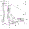
The utility model provides a seat for vehicle, aim at ensure the location nature of line fastener and will connect the terminal portion outward appearance of back line fastener and accomodate the dorsal part in the seat cover more well. In a vehicle seat in which a distal end portion (10E) of a connected wire clip (10) can be inserted and stored in the back side of either a first skin material (SP1) or a second skin material (SP2), a mat material (20) that spreads in a planar manner is arranged on the back side of the first skin material (SP1), a cover-side fixing portion (31) that fixes a part of the mat material (20) to the first skin material (SP1) and a clip-side fixing portion (32) that fixes only the distal end portion (10E) of the wire clip (10) and the mat material (20) are provided, and the mat material portion other than the part can move relative to the first skin material (SP1) and follow the distal end portion (10E) of the connected wire clip (10).
Description
Technical Field
The utility model relates to a seat cover that constitutes the outward appearance of seat possesses first skin spare, second skin spare and the line fastener's that connects the edge of first skin spare and second skin spare each other seat for vehicle.
Background
Such seat covers are typically formed of a plurality of skin members, and the edges of the adjacent skin members are sewn together to be integrated with each other or are detachably connected by a thread fastener. For example, in the case of a seat back functioning as a backrest, a bag-shaped seat cover has a skin material on a frame surface side to be a seat side surface and a skin material on a back surface side, and covers internal components such as a seat frame and a seat cushion. In addition, in consideration of convenience in arranging the seat cover, the edges of the cover may be detachably connected to each other by a wire fastener extending in the vertical direction. That is, when the seat cover is disposed, the wire fastener is opened to expand the space between the two skin members, so that the seat cover can smoothly cover the inner member of the seat back. Then, in order to change the seat cover after the covering work into a bag shape again, the wire fastener is closed up to the lower end portion, and the edges of the two cover members are connected to each other.
Here, from the viewpoint of ensuring the appearance of the seat, it is preferable that the terminal portion of the connected wire clip is not exposed to the outside in a state of being kept intact. For example, a seat back for an automobile disclosed in patent document 1 includes a seat cover corresponding to a seat cover of the present invention and a slide fastener corresponding to a wire fastener of the present invention. The seat cover has a pair of cover members adjacent to each other, and a slide fastener is disposed between the pair of cover members. The slide fastener has a tape sewn to an edge of one of the surface members, another tape sewn to an edge of the other surface member, and a slider connecting the two tapes. Further, in the known art, the positioning of the slide fastener with respect to the seat skin is ensured by sewing each tape to the corresponding skin piece until the tip end is near. A tubular cloth storage section is attached to the end of the tape, and the connected end portion of the slide fastener is stored in the storage section. That is, the slider is stored in the storage portion so as to be slid to the distal end portion and close the slide fastener without exposing the distal end portion of the connected slide fastener to the outside, whereby deterioration of the seat appearance can be avoided to some extent.
Patent document 1: japanese patent No. 5477641 Specification
SUMMERY OF THE UTILITY MODEL
Problem to be solved by utility model
However, in the known art, since the storage portion itself is exposed to the outside and the position of the terminal portion of the connected slide fastener (wire fastener) is known, there is a structure that is not suitable for maintaining the excellent appearance of the seat. However, the connected wire clip may be bent so that the distal end portion thereof is inserted into the back side of the skin material on the frame surface side and stored therein. However, in such a structure, the position of the skin material may be displaced by deformation or the like due to insertion of the distal end portion, which is not preferable from the viewpoint of maintaining the appearance of the seat cover. For example, the skin material on the back surface side deforms so as to be recessed following the distal end portion, and the seat cover may wrinkle, and a gap (e.g., a triangular gap) may be formed at a matching position with the skin material on the frame surface side. Further, when a gap is formed between the two skin members, the structure inside the seat may be exposed through the gap, and undesired light leakage may occur from the gap when the seat is viewed from the seating surface side. The present invention has been made in view of the above circumstances, and an object of the present invention is to provide a seat cover that can ensure the positioning of a wire fastening member and can house the end portion of the connected wire fastening member in the back side of the seat cover with a more excellent appearance.
Means for solving the problems
As a means for solving the above problems, a vehicle seat according to claim 1 is a seat cover that constitutes an appearance of the seat, the seat cover including a first cover member, a second cover member disposed adjacent to the first cover member, and a wire fastener that connects edges of the first cover member and the second cover member to each other. The edges of the first and second skins are closed to the distal end portion by the fastener, and the distal end portion of the connected fastener can be inserted into the back side of either the first or second skin and stored therein. In this configuration, the terminal portion of the connected wire clip can be housed in the back side of the seat cover with a better appearance while securing the positioning performance of the wire clip.
Therefore, in the vehicle seat of the present invention, the cushion material that spreads out in a planar shape is disposed on the back surface of the first cover material, and the cover-side fixing portion that fixes the first cover material and a part of the cushion material and the hook-side fixing portion that fixes only the distal end portion of the hook and the cushion material are provided. The mat portion other than the part can move relative to the first skin member and follow the terminal portion of the connected wire fastener. The end portion of the wire clip of the present invention is fixed only to the mat material by the clip-side fixing portion, and the first skin member is in an unfixed state. Therefore, when the terminal portion of the connected wire clip is stored, the first cover member can be maintained at the predetermined position without following the insertion of the terminal portion as much as possible, and the structure is advantageous for ensuring the excellent appearance of the seat cover. In the present invention, the distal end portion of the wire clip is fixed to the mat member by the clip-side fixing portion in a state where a part of the mat member is fixed to the back side of the first cover member by the sleeve-side fixing portion. Therefore, even in a state where the fastener before connection is not fixed to the first skin material, the fastener can be positioned and arranged at an appropriate position of the first skin material through the mat member.
In the vehicle seat according to claim 2, in the vehicle seat according to claim 1, the cushion member is in a state of being spread in the surface direction so as to be along the back surface of the first skin member and being sandwiched between the first skin member and the inner member in the seat covered with the first skin member. In the present invention, the mat material in the expanded state is held by the first skin member and the internal member, so that the wire fastening member can be positioned and arranged more stably via the mat material.
The vehicle seat according to claim 3 is the vehicle seat according to claim 2, wherein the seat frame serving as a seat frame is provided as an inner member, and fastening holes for fastening to a vehicle floor are provided in an edge portion of the seat frame on the vehicle floor side. The distal end portion of the wire clip is disposed on the vehicle floor side, and the sleeve-side fixing portion is disposed farther from the vehicle floor than the fastening hole. The present invention can be applied to a case in which a terminal portion of a connected fastener is inserted into a back side of a corresponding skin member using a fastening hole as a mark. In this case, by providing the cover-side fixing portion at a position farther from the vehicle floor than the fastening hole, it is possible to more reliably avoid the case where the first skin portion fixed to the wire fastener by the cover-side fixing portion follows the insertion of the distal end portion.
In the vehicle seat according to claim 4, in any one of claims 1 to 3, the cover-side fixing portion and the buckle-side fixing portion are provided adjacent to each other in the extending direction of the wire buckle, and the pad material is fixed to the wire buckle portion adjacent to the distal end portion and the first skin material portion arranged to overlap the wire buckle portion by the cover-side fixing portion. The utility model discloses in, arrange the extending direction of fastener along fastener side fixed part and cover side fixed part and set up, will fill up material through cover side fixed part and be fixed in both sides of fastener and first epidermis piece. Thus, the wire fastener can be positioned and arranged more reliably via the mat member.
In the vehicle seat according to claim 5, in the vehicle seat according to any one of claims 1 to 4, the pad has an edge portion disposed on the distal end portion side that is longer than an opposite edge portion. In the present invention, the edge portion on the larger-sized distal end side can be used as a hand-held portion, and the mat member can be appropriately spread in a planar shape.
The vehicle seat according to claim 6 is the vehicle seat according to any one of claims 1 to 5, wherein the cushion material is formed of a surface material thinner than the first surface material. In the present invention, the mat member disposed on the back side of the first skin member is relatively thin, so that it is possible to avoid as much as possible the occurrence of unnatural unevenness in the first skin member due to the mat member.
In the vehicle seat according to claim 7, in the vehicle seats according to claims 1 to 6, the first skin member and the second skin member have different appearances from each other, and the mat material has an appearance that is not similar to the second skin member but similar to the first skin member. In the present invention, the first cover member and the cushion member have similar appearances, and thus the interior member in the seat can be covered with the appearance more favorably by these two members.
Effect of the utility model
According to the utility model relates to an aspect 1 can ensure the location nature of line fastener to the terminal portion outward appearance of the line fastener after will connecting is accomodate in the dorsal part of seat cover more well. Further, according to claim 2, the terminal portion of the wire clip can be positioned more stably. Further, according to claim 3, the terminal portion of the connected wire clip can be stored on the back side of the seat cover more reliably and with good appearance. Further, according to claim 4, the terminal portion of the wire clip can be positioned more stably. Further, according to claim 5, the terminal portion of the connected wire clip can be stored more favorably on the back side of the seat cover while ensuring an appropriate arrangement state of the bolsters. Further, according to claim 6, the terminal portion of the connected wire buckle can be accommodated in the back side of the seat cover more appropriately in appearance. Further, according to claim 7, the terminal portion of the connected wire buckle can be accommodated in the back side of the seat cover more appropriately in appearance.
Drawings
Fig. 1 is a perspective view of a vehicle seat.
Fig. 2 is a perspective view of each seat back as viewed from the seating side.
Fig. 3 is a rear view of each seat back as viewed from the rear surface side.
Fig. 4 is an enlarged perspective view of the right seat back showing the wire clip when stowed.
Fig. 5 is a schematic rear view showing the arrangement relationship of the components at the lower portion of each seat back.
Fig. 6 is an expanded view of the respective skin pieces and the wire fasteners of the right side seat back.
Fig. 7 is a perspective view of the components when the first skin member is formed.
Fig. 8 is a perspective rear view of the components after the first skin member is formed.
Fig. 9 is a rear view of the members after the second skin member is formed.
Fig. 10 is an expanded view of the respective skin members and wire fasteners of the left side seat back.
Fig. 11 is a schematic enlarged rear view showing the arrangement relationship of the members after the seat back is formed.
Fig. 12 is an enlarged perspective view of the right seat back showing the wire fasteners after attachment.
FIG. 13 is a cross-sectional view of the left seat back taken along line XIII-XIII in FIG. 5.
FIG. 14 is a cross-sectional view of the right side seat back taken along line XIII-XIII in FIG. 5.
FIG. 15 is a cross-sectional view of the left seat back of FIG. 5 taken along line XIV-XIV.
FIG. 16 is a cross-sectional view of the right side seat back of FIG. 5 taken along line XIV-XIV.
FIG. 17 is a cross-sectional view of the left seat back taken along line XV-XV of FIG. 5.
FIG. 18 is a cross-sectional view of the right seat back taken along line XV-XV of FIG. 5.
Fig. 19 is an enlarged cross-sectional view of the right seat back at a position corresponding to fig. 18.
Detailed Description
Hereinafter, a mode for carrying out the present invention will be described with reference to fig. 1 to 19. For convenience, the drawings appropriately illustrate arrows indicating the front-rear direction, the left-right direction, and the up-down direction of the vehicle seat. The left and right seat backs (6, 7) shown in fig. 1 are disposed adjacent to each other with almost no gaps therebetween, but the left and right seat backs (6, 7) are shown separated from each other in fig. 5 and 13 to 18 for convenience.
The vehicle seat 2 shown in fig. 1 is a seat on which a plurality of occupants can sit, and includes a seat cushion 4, a right seat back 6 for a plurality of persons, and a left seat back 7 for one person. Here, the seat cushion 4 is a member that serves as a seat for an occupant, and has a long dimension in the seat width direction so as to enclose the pair of right and left seat backs 6, 7. As shown in fig. 2, a pair of right and left seat backs 6, 7, which will be described later, are disposed behind the seat cushion 4 in a state of being adjacent in the right-left direction, which is the seat width direction (a state of having almost no slit C). The right seat back 6 disposed on the right side has a long dimension in the seat width direction, and the left seat back 7 disposed on the left side has a short dimension in the seat width direction. The right side of the right seatback 6 is a normal seatback portion, and on the left side, the armrests 6C are disposed so as to be able to stand and lie down. The armrest 6C can be used as a normal seat back portion by standing up, and can also be used as an armrest portion by falling down toward the seat cushion 4.
[ seat back ]
The pair of right and left seat backs 6, 7 shown in fig. 1 to 3 are members serving as backrest of a seat occupant, and have substantially the same basic configuration except for the right and left dimensions. For example, the right seat back 6 shown in fig. 2 has, as a basic structure, a seat frame 6F serving as a seat frame, a seat cushion 6P serving as a seat outer shape and elastically supporting an occupant, and a seat cover 6S constituting an outer appearance of the seat. The seat cover 6S is composed of a plurality of skin members as described later, and edges of specific skin members (SP1, SP2) shown in fig. 3 and 4 are detachably connected to each other by a wire fastener 10 described later. The left seat back 7 shown in fig. 2 also includes another seat frame 7F, another seat cushion 7P, and another seat cover 7S. The specific skin members (SP11, SP12) shown in fig. 3 of the other seat cover 7S are also connected by the other wire fasteners 100.
Further, with reference to fig. 3 and 4, after the covering operation of the seat cover 6S described later, the wire fastener 10 is closed to the distal end portion 10E, and the edges of the specific skin materials (SP1, SP2) are connected to each other, in the right seat back 6. The terminal portion 10E of the connected wire buckle 10 is inserted and stored in the back side of the seat cover 6S in consideration of the appearance of the seat and the like. In the left seat back 7 shown in fig. 3 as well, the distal end portion (not shown) of the other wire buckle 100 connected thereto is inserted into the back side of the other seat cover 7S and stored therein. In such a configuration, it is desirable to store the terminal portion 10E of the connected wire buckle 10 and the like on the back side of the seat cover 6S and the like in a more satisfactory appearance while securing the positioning property of the wire buckle 10 and the like. Therefore, in the present embodiment, the positioning of the wire anchor 10 and the like is ensured by the configuration (the pad 20 and the like) described later, and the distal end portion 10E of the connected wire anchor 10 and the like is stored in the back side of the seat cover 6S and the like in a more favorable appearance. Here, the right seat back 6 and the left seat back 7 have substantially the same basic structure, and therefore the details thereof will be described below with the right seat back 6 taken as an example.
[ seat cushion, seat frame (inner member) ]
Here, referring to fig. 14 and the like, the seat cushion 6P is a member having a substantially rectangular shape in a front view constituting the outer shape of the seat, and can be formed of a foamed resin such as a urethane foam (density: 10kg/m3 to 60kg/m3), for example. Typically, the seat frame 6F is a tubular or plate-shaped member, and can be formed of a material having excellent rigidity, such as metal or hard resin. The seat frame 6F is covered with a seat cover 6S described later while supporting the seat cushion 6P from the rear side (the rear side in the drawings). Referring to fig. 3 and 5, a fastening hole 6FH for fastening to the vehicle floor FS (bracket BR) is provided on the lower edge side of the seat frame 6F on the vehicle floor side. That is, the seat frame 6F is fastened and fixed to a bracket BR disposed on the vehicle floor FS via a fastener (not shown) inserted through the fastening hole 6FH. The right seat back 6 is provided with round hole-shaped fastening holes 6FH (through holes) at the left and right lower ends of the seat frame 6F, respectively, so that the right and left brackets BR can be fastened and fixed thereto (in fig. 5, only a part of the seat frame and the left fastening hole are illustrated for convenience). In the present embodiment, the seat frame 6F corresponds to an internal member in the seat of the present invention, and is covered with a seat cover 6S described later.
[ seat cover ]
The seat cover 6S of the right seat back 6 shown in fig. 2 to 4 and 14 is formed of a plurality of skin members, and includes a wire fastener 10 and a bolster 20 (for convenience, specific skin members are denoted by specific reference numerals SP1 and SP2, and other skin members are denoted by a common reference numeral SP in the drawings). The seat cover 6S is formed in a bag shape having a lower side opened, and can cover the seat cushion 6P and the seat frame 6F from the upper side as described later. A J-hook (not shown) having a J-shaped cross section is attached to a lower edge of the seat cover 6S, and can be locked to the seat frame 6F or the like by the J-hook.
[ first skin piece/second skin piece ]
As shown in fig. 3 and 4, the first skin material SP1 on the seat back surface 6A side and the second skin material SP2 on the left side surface (left frame surface 6B) of the seat are disposed adjacent to the seat cover 6S. The first cover SP1 is formed in a substantially horizontally long rectangular shape along the rear surface 6A of the right seat back 6, and a cushion member 20 described later is disposed on the rear side thereof. Referring to fig. 5, the left edge E1 of the first skin material SP1 extends substantially straight in the vertical direction, but a folded portion 6SS recessed in a stepped manner toward the right is formed on the lower end side of the left edge E1. Referring to fig. 6 and 7, the folded portion 6SS is formed by folding back a portion (X) provided below the left edge E1 and protruding in the left direction and sewing it to the back side of the first skin material SP1 with a suture thread SEW. Therefore, the left edge E1 portion formed by the folded portion 6SS has a greater thickness than other portions, and has improved rigidity, and is disposed linearly along the upper and lower sides with good workability. The second skin material SP2 shown in fig. 4 and 6 is formed into a substantially rectangular shape having a vertically long dimension along the left frame surface 6B, and has an upper end portion and a lower end portion that protrude forward with a relatively wide width. Further, a portion between the upper end portion and the lower end portion of the second skin member SP2 is a concave shape which is narrow and is relatively recessed rearward, and the armrest 6C shown in fig. 2 is disposed in this concave portion.
[ Material (appearance) of each skin article ]
Here, the material of each of the cover materials (SP1, SP2, and the like) shown in fig. 6 is not particularly limited, but may be formed of a surface material such as cloth (woven fabric, knitted fabric, nonwoven fabric), leather (natural leather, synthetic leather), or the like that can configure the appearance of the seat. Further, an inner material such as a cushion material (e.g., a polyurethane laminate) or a back base fabric can be appropriately integrated on the back side of the surface material. Referring to fig. 7, the thickness dimension T1 of each skin material (SP1, etc.) can typically be defined by the total thickness of the surface material and the lining material, and when the lining material is omitted, it can be defined by the thickness of the surface material alone. Further, the first skin member SP1 (surface material) and the second skin member SP2 (surface material) may have substantially the same appearance or may have different appearances from each other. The difference in appearance between the two skin materials (SP1, SP2) can be typically identified by at least one of the three elements of color (hue, brightness, chroma), and particularly preferably by hue (type of color). For example, in the present embodiment, the first skin member SP1 and the second skin member SP2 shown in fig. 4 are formed of materials having different hues so as to have different appearances. That is, the first skin material SP1 is colored in black due to the arrangement on the back surface 6A side. The second skin material SP2 is colored in a relatively bright color (for example, white), and the difference from the first skin material SP1 can be visually recognized.
[ thread fastener ]
In the seat cover 6S shown in fig. 2, referring to fig. 4 to 6, the first skin material SP1 and the second skin material SP2 can be connected by the wire fastener 10, and the other skin materials can be integrated by sewing (a method of attaching the wire fastener will be described later). Referring to fig. 4 and 6, the wire clip 10 includes a first clip piece 11 attached to a left edge E1 of a first skin piece SP1, a second clip piece 12 attached to a rear edge E2 of a second skin piece SP2, and a slider 13. The first fastening piece 11 and the second fastening piece 12 are belt-shaped members long in the vertical direction. The inner edge side IS of each of the fastener pieces 11, 12 IS sewn to the corresponding skin material, and the outer edge sides OS of the fastener pieces 11, 12 facing each other are provided with engaging teeth capable of engaging with each other. The slider 13 is a plate member attached between the fastener pieces 11 and 12, and can slide from top to bottom while engaging the engaging teeth of the fastener pieces 11 and 12 with each other. In the covering operation of the seat cover 6S described later, the slider 13 is pulled upward to bring the fastener pieces 11 and 12 into a non-connected state, thereby bringing the wire fastener 10 into an open state. After the seat cover 6S is sewn, the slider 13 is pulled downward to bring the fastener pieces 11 and 12 into a connected state, thereby bringing the wire fastener 10 into a closed state. In the closed state of the fastener 10, the slider 13 is located at the lower end side of the fastener 10, and the portion where the slider 13 is located becomes the tip end portion 10E (described in detail later), and is disposed on the back side of the second skin material SP2 so as to be able to be stored therein.
[ Mat Material ]
The mat 20 shown in fig. 3 to 6 is a surface material disposed on the lower left side of the first skin material SP1, and is spread in a planar manner so as to extend along the back surface of the first skin material SP1. The mat member 20 is formed in a rectangular shape with a right-angle cut away in a planar state shown in fig. 6, and the cut away portion is an inclined edge portion 20e that gradually inclines downward toward the right. The mat 20 has a periphery excluding the inclined edge 20e formed by a left edge 20a at the left end, a right edge 20b at the right end, an upper edge 20c at the upper end, and a lower edge 20d at the lower end. The left edge portion 20a is an edge extending vertically so as to be along the left edge E1 of the first skin material SP1, and is longer than the right edge portion 20b extending vertically in the same manner. The upper edge 20c extends leftward from the upper end of the left edge 20a, and the lower edge 20d extends leftward from the lower edge of the left edge 20a. The inclined edge 20e is formed between the upper edge 20c and the right edge 20b, and the right side of the upper edge 20c is cut away by the inclined edge 20e. The lower edge portion 20d is an edge disposed on the terminal end portion 10E side of the fastener 10 after being covered, and has a larger length dimension in the left-right direction than the upper edge portion 20c whose right side is cut out. That is, in the present embodiment, the lower edge portion 20d corresponds to an edge portion disposed on the distal end portion side of the present invention, and the upper edge portion 20c corresponds to an edge portion on the opposite side of the present invention.
[ Material (appearance and thickness dimension) of Mat Material ]
Here, as the material of the cushion member 20, a material having appropriate rigidity and flexibility can be used, and as such a material, the material exemplified in the seat cover 6S can be used. Also, referring to figure 4, it is preferred that the mat material 20 not have an appearance similar to the second skin piece SP2 (skin material) but similar to the first skin piece SP1 (skin material). Here, the appearance similarity means that the hues (types of colors) are the same, and the chroma and the brightness may be different. For example, the mat 20 of the present embodiment is colored in black having the same appearance as the first skin material SP1, and can be visually confirmed to have a similar appearance to the first skin material SP1. Referring to fig. 7, the mat 20 preferably has a thickness T2 smaller than the thickness T1 of the first skin material SP1, and in this embodiment, is formed of a surface material thinner than the first skin material SP1. In addition, the thickness dimension T2 of the mat member 20 can be set smaller than the total thickness of the front material and the inner material when the first skin material SP1 is composed of the front material and the inner material. The thickness T2 of the mat 20 can be set smaller than the surface material when the first skin material SP1 is made of only the surface material.
[ work for attaching the first fastener piece and the cushion Material ]
In the operation of attaching the wire clip 10, as shown in fig. 7 and 8, the first clip piece 11 shown in fig. 6 is brought into contact with the front side of the first skin material SP1 (in fig. 8, the left and right positions of the respective members are shown slightly shifted for convenience). At this time, the first fastening piece 11 is overlapped (overlapped) from the front side of the first skin piece SP1 on the left edge E1 side, and is disposed from the upper portion of the first skin piece SP1 toward the folded-back portion 6SS. The lower portion of the first fastening piece 11 is not overlapped with the left edge E1 side of the first skin material SP1 from the recessed folded back portion 6SS downward, and is further disposed to slightly protrude from the lower edge of the first skin material SP1. At the same time, the mat 20 in the expanded state is abutted against the back side of the first skin material SP1. At this time, the left edge portion 20a of the mat 20 is aligned with the left edge E1 from the back side of the first skin material SP1, and the upper portion of the mat 20 is overlapped with the portion of the first skin material SP1 above the folded portion 6SS. The lower portion of the left edge portion 20a of the mat 20 is arranged so as not to overlap the first skin material SP1 from the concave folded-back portion 6SS downward, and so as to overlap the first fastening sheet 11 as it is. In this way, in the present embodiment, three overlapping portions where the first skin material SP1, the first fastening sheet 11, and the mat material 20 overlap are formed above the folded-back portion 6SS shown in fig. 8. Further, two overlapped portions where the first fastening sheet 11 and the cushion material 20 are directly overlapped are formed below the folded-back portion 6SS.
[ formation of Sleeve-side fixing portion ]
Thus, referring to fig. 8, the first fastener piece 11 is sewn by the first sewing thread SEW1 from top to bottom to the left edge E1 side of the first skin piece SP1. In this case, three overlapping portions where the first skin material SP1, the first fastening piece 11, and the mat material 20 overlap are formed above the folded-back portion 6SS in the present embodiment. Therefore, the first suture thread SEW1 that SEWs the three overlapped portions forms the sheath-side fixing portion 31 that fixes (a part of) the upper portion of the left edge portion 20a of the mat 20 to the first cover material SP1. The cover-side fixing portion 31 is formed above the folded portion 6SS in a state extending in the vertical direction toward the hook fastener 10. In this embodiment, the first fastener piece 11 forming the three overlapping portions corresponds to the wire fastener portion adjacent to the terminal portion of the present invention, and the first skin member SP1 forming the three overlapping portions corresponds to the first skin member portion arranged to overlap with the wire fastener portion of the present invention.
[ formation of fastener-side fixing portion ]
Next, as shown in fig. 8, the first suture line SEW1 is formed at the portion of the first fastener piece 11 disposed below from the folded-back portion 6SS of the first skin material SP1. Further, two overlapped portions where the first fastening sheet 11 and the cushion member 20 are directly overlapped with each other are formed at a portion located downward from the folded portion 6SS. Therefore, the fastener-side fixing portion 32 for fixing only the first fastener piece 11 and the lower portion of the cushioning material 20 is formed by sewing the two overlapped first sewing threads SEW1. In this way, the hook-side fixing portion 32 is formed in a state of extending in the vertical direction toward the hook 10, and is disposed adjacent to the lower side of the cover-side fixing portion 31. The lower portion of the first fastener piece 11 is not fixed to the first cover material SP1 by being disposed downward from the folded-back portion 6SS, and is positioned to form a part of the distal end portion 10E of the wire fastener 10. In the present embodiment, the hook-side fastening portion 32 and the cover-side fastening portion 31 are arranged in the vertical direction in which the hook fastener 10 extends, and the mat 20 is fixed to both the first fastener sheet 11 and the first cover material SP1 by the cover-side fastening portion 31. In this way, even if the lower portion of the first fastening piece 11 is not directly fixed to the first skin material SP1, it can be positioned and arranged with respect to the first skin material SP1 via the mat 20.
[ mounting work of second fastener piece ]
Before and after the above-described operation, as shown in fig. 9, the second fastener piece 12 of the front side suture fastener 10 of the second skin material SP2 is sewn with the second suture threads SEW2, and the second fastener piece 12 is arranged in parallel with the first fastener piece 11. At this time, the second fastening piece 12 is overlapped (overlapped) from the front side of the second skin piece SP2 to the rear edge E2 side, and is extended downward from the upper portion of the second skin piece SP2, and is further disposed to slightly protrude from the lower edge of the first skin piece SP1. In this state, the second fastener piece 12 is sewn with the second sewing thread SEW2 to the rear edge E2 side of the second skin member SP2 from the top to the bottom end of the second skin member SP2. The lower portion of the second fastener piece 12 is located at a position where the other portion of the terminal portion 10E of the fastener 10 described later is formed, and is arranged at a position where it can be connected to the lower portion of the first fastener piece 11.
[ left side seat back ]
The left seat back 7 shown in fig. 3 includes another first cover member SP11 on the back surface 7A side, another second cover member SP12 on the right frame surface 7B side, another wire fastener 100, and another cushion member 200. These various other skin pieces SP1, SP2, other wire fasteners 100, and other bolsters 200 have substantially the same basic structure as the corresponding components of the right seat back 6. In addition, in the left seat back 7, another first hook piece 111 and another cushion member 200 may be fixed to another first skin member SP11 shown in fig. 10 so as to be bilaterally symmetrical to the right seat back 6. That is, three overlapped portions where the other first skin material SP11, the other first fastening piece 111, and the other cushion member 200 are overlapped are formed above the other folded back portion 7SS in the left side seatback 7. Further, by sewing the other first sewing thread (not shown) of the three overlapped portions, a sheath-side fixing portion (not shown) for fixing the upper portion of the other mat 200 to the other first skin material SP11 can be formed. Further, two overlapped portions where the other first fastener piece 111 and the other cushion member 200 are directly overlapped are formed below from the other folded-back portions 7SS. Further, by sewing the other first sewing thread of the two overlapped portions, a fastener-side fixing portion (reference numeral omitted) for fixing only the other first fastener piece 111 and the other mat 200 can be formed. Before and after the above-described operation, the other second fastening piece 112 is sewn to the front side of the other second skin material SP12 and is arranged in parallel with the other first fastening piece 111. The lower portions of the other two fastener pieces 111 and 112 are positioned to form the end portions of the other thread fastener 100 on the rear surface.
[ Forming work of seat Back ]
Here, the right seat back 6 and the left seat back 7 shown in fig. 1 to 3 have substantially the same basic configuration, and the forming work is substantially the same. Therefore, the details of the forming operation of the right seat back 6 will be described below by taking the right seat back as an example. In the right seat back 6, referring to fig. 3 and 11, left and right lower end portions of a seat frame 6F are fastened and fixed to a bracket BR having a substantially inverted L shape in a rear view, and rise from a vehicle floor FS (in fig. 11, only a part of the seat frame and a fastening hole on the left side are illustrated for convenience). Therefore, the bag-shaped seat cover 6S covers the back side of the seat cushion 6P in a state where the back side of the seat cushion 6P is supported by the seat frame 6F. At this time, in the seat cover 6S shown in fig. 12, the slider 13 is moved upward to open the buckle 10 (see the slider shown by the broken line in fig. 14). By thus expanding the space between the first skin member SP1 and the second skin member SP2, the seat cover 6S can be smoothly covered on the seat cushion 6P and the seat frame 6F. After the seat cover 6S is completely covered, the slider 13 is moved downward to close the fastener 10 to the distal end portion 10E, and the edges of the first skin material SP1 and the second skin material SP2 are connected to each other (see the slider shown by the solid line in fig. 14). The terminal portion 10E of the connected wire fastener 10 is formed by the first fastener piece 11 portion and the second fastener piece 12 portion located below the folded-back portion 6SS of the first skin material SP1.
As described above, the seat cover 6S is formed into a bag shape by connecting the skin members SP1 and SP2 shown in fig. 12, and thereby covers the seat cushion 6P and the seat frame 6F as shown in fig. 14, 16, and 18. However, in the present embodiment, referring to the portion surrounded by the circle in fig. 16, the first skin material SP1, the first fastener piece 11, and the mat 20 are overlapped and sewn at the formation position of the sheath-side fixing portion 31. It can be said that the seat cover portion formed with the cover-side fixing portion 31 has a larger thickness than the portion on the upper side thereof (the portion of the first skin material SP1 and the first fastening piece 11 surrounded by the circle of fig. 14), and is a position where unwanted irregularities are likely to be formed. Therefore, in the present embodiment, as shown in fig. 7, the thickness of the mat 20 disposed on the back side of the first skin material SP1 is intentionally reduced. Therefore, the seat cover portion formed with the cover-side fixing portion 31 shown in fig. 16 can avoid as much as possible the occurrence of unnatural irregularities due to the cushion material 20, and is configured to contribute to ensuring an excellent appearance of the seat cover 6S.
Before and after the above-described connecting operation, the lower end of the seat cover 6S shown in fig. 4 can be locked to the seat cover 6S via the J-hooks. During this locking operation, the mat 20 is spread in the planar direction (vertical and horizontal directions) so as to be along the back side of the first cover material SP1. In this case, in the present embodiment, since the relatively large-sized lower edge portion 20d of the mat 20 is disposed downward, the mat 20 can be appropriately spread out in a planar shape by using the lower edge portion 20d as a hand-held portion. As shown in fig. 11, the mat 20 in the expanded state is sandwiched between the first cover SP1 and the seat frame 6F, whereby the lower portion of the first fastening piece 11 can be positioned and arranged more stably via the mat 20.
[ accommodation of terminal part of wire clip after connection ]
In the present embodiment, referring to fig. 4 and 12, the connected wire clip 10 is folded back in the middle, and the distal end portion 10E thereof is inserted and stored on the back side of the second skin material SP2. In such a configuration, it is desirable to store the terminal portion 10E of the connected wire buckle 10 on the back side of the seat cover 6S in a more satisfactory appearance. That is, when the first cover SP1 is deformed so as to follow the distal end portion 10E and to be recessed toward the right front side due to the insertion of the distal end portion 10E, it is not preferable from the viewpoint of maintaining the appearance of the seat cover 6S. For example, referring to fig. 18 and 19, a case is assumed where the position P1 of the lower left edge portion (folded portion 6SS) is shifted forward and rightward by the depression of the first skin material SP1. In such a case, a gap (e.g., a triangular gap) may be formed between the first skin member SP1 and the second skin member SP2, and the seat frame 6F and the like may be exposed through the gap. Further, referring to fig. 2, when the seat backs 6 and 7 are viewed from the seating surface side, there is also a possibility that undesired light leakage occurs from the gap C between the seat backs 6 and 7 due to the gap (triangular gap or the like) between the skin members.
Therefore, in the present embodiment, referring to fig. 4, the mat 20 spread in a planar shape is disposed on the back surface of the first skin material SP1, and the sheath-side fixing portion 31 for fixing the first skin material SP1 and a part of the mat 20 and the fastener-side fixing portion 32 for fixing only the distal end portion 10E of the fastener 10 and the mat 20 are provided. The mat portion other than the portion (the upper portion of the left edge portion 20 a) is movable relative to the first covering material SP1 to follow the distal end portion 10E of the connected fastener 10. That is, only the mat 20 is fixed to the distal end portion 10E of the fastener 10 by the fastener-side fixing portion 32, and the first skin material SP1 is in an unfixed state. When the terminal portion 10E of the connected fastener 10 is stored, the first skin material SP1 can be maintained at the predetermined position P1 without following the insertion of the terminal portion 10E as much as possible. Therefore, the operation of the above-described cushion member 20 and the fixing portions 31 and 32 will be described in more detail below with reference to the right seat back 6 as an example.
Referring to fig. 12, in a state where the terminal portion 10E is closed to the wire clip 10, the terminal portion 10E of the connected wire clip 10 is disposed so as to cross the fastening hole 6FH of the seat frame in the vertical direction. Therefore, referring to fig. 4 and 12, the terminal portion 10E of the connected wire clip 10 can be inserted into the back side of the second surface material SP2 with the fastening hole 6FH as a mark (with the height position as a reference) by folding back the wire clip 10 in the forward direction. At this time, only the mat 20 is fixed to the distal end portion 10E of the fastener 10 by the fastener-side fixing portion 32, and the lower left edge portion (folded-back portion 6SS) of the first skin material SP1 is in an unfixed state. Therefore, when the distal end portion 10E is stored, the lower left edge portion (the folded portion 6SS) of the first skin material SP1 can be maintained at the predetermined position P1 without following the insertion of the distal end portion 10E as much as possible. Further, by maintaining the first skin member SP1 at the predetermined position P1, it is possible to avoid generation of wrinkles in the seat cover 6S or generation of a gap (triangular gap) with the second skin member SP2 as much as possible. In the present embodiment, referring to fig. 4 and 11, the sleeve-side fixing portion 31 is provided at a position farther from the vehicle floor FS than the fastening hole 6FH. Thus, the first skin material SP1 fixed to the wire fastener 10 by the cover-side fixing portion 31 can be prevented as much as possible from being excessively stretched by the distal end portion 10E, and the occurrence of an undesired wrinkle in the seat cover 6S can be prevented as much as possible.
As shown in fig. 4, the terminal portion 10E of the connected wire fastener 10 is inserted into and housed on the back side of the second cover material SP2, so that the exposure of the terminal portion 10E to the outside can be avoided as much as possible. In the present embodiment, the mat 20 is fixed to the end portion 10E of the fastener 10 via the fastener-side fixing portion 32. Therefore, the mat member 20 is relatively moved so as to be pulled out from the back side of the first cover SP1, and is moved to the front side following the insertion of the distal end portion 10E, so that it can be arranged to cover the seat frame 6F from the left side. By disposing the mat 20 so as to cover the left side of the seat frame 6F in this way, exposure of the seat frame 6F to the outside can be avoided more reliably. Further, in the present embodiment, since the first skin member SP1 and the mat member 20 have similar appearances, the seat frame 6F can be covered with these two members more favorably in appearance.
As described above, in the terminal portion 10E of the wire fastener 10 of the present embodiment, only the mat 20 is fixed by the fastener-side fixing portion 32, and the first cover SP1 is in an unfixed state. Therefore, when the terminal portion 10E of the connected buckle 10 is stored, the first cover SP1 can be maintained at the predetermined position without following the insertion of the terminal portion 10E as much as possible, and the structure is advantageous for ensuring the excellent appearance of the seat cover 6S. In the present embodiment, the distal end portion 10E of the wire fastener 10 is fixed to the mat member 20 by the fastener-side fixing portion 32 in a state where a part of the mat member 20 is fixed to the back side of the first skin material SP1 by the sheath-side fixing portion 31. Therefore, even in a state where the fastener 10 before connection is not fixed to the first skin material SP1, it can be positioned and arranged at an appropriate position of the first skin material SP1 via the mat 20. Therefore, according to the present embodiment, the distal end portion 10E of the connected wire buckle 10 can be housed in the back side of the seat cover 6S more favorably in appearance while securing the positioning performance of the wire buckle 10. In addition, also in the left seat back 7, the distal end portion of the other wire buckle 100 after the connection can be stored in the back side of the other seat cover 7S more satisfactorily.
In the present embodiment, the mat 20 in the expanded state is sandwiched between the first cover SP1 and the seat frame 6F (inner member), whereby the wire fastener 10 can be positioned and arranged more stably via the mat 20. In the present embodiment, the terminal portion 10E of the connected fastener 10 can be inserted and stored in the back side of the corresponding cover material with the fastening hole 6FH as a mark. At this time, by providing the cover-side fixing portion 31 at a position farther from the vehicle floor than the fastening hole 6FH, it is possible to more reliably avoid the situation in which the first cover SP1 fixed to the fastener 10 by the cover-side fixing portion 31 partially follows the insertion of the distal end portion 10E. In the present embodiment, the hook-side fastening portion 32 and the cover-side fastening portion 31 are arranged in the extending direction of the hook fastener 10, and the mat member 20 is fastened to both the hook fastener 10 and the first cover material SP1 by the cover-side fastening portion 31. In this way, the fastener 10 can be positioned and arranged more reliably via the mat 20. In the present embodiment, the mat 20 can be appropriately spread out in a planar shape by using the edge portion (lower edge portion 20d) on the side of the relatively large-sized terminal portion 10E as a hand-held portion. In the present embodiment, the mat 20 disposed on the back side of the first skin material SP1 is relatively thin, and thus the occurrence of unnatural unevenness (protrusion) of the first skin material SP1 due to the mat 20 can be avoided as much as possible. Further, in the present embodiment, the first skin member SP1 and the mat member 20 have similar external appearances, and therefore the seat frame 6F and the seat cushion 6P (other examples of the internal member) can be covered with these two members more favorably in appearance. Also in the left seat back 7, the same effects as those of the right seat back 6 are exerted by the components (SP11, 12, 100, 200, etc.).
The vehicle seat 2 of the present embodiment is not limited to the above-described embodiment, and various other embodiments can be obtained. In the present embodiment, the structure (shape, size, arrangement position, structural members, and the like) of the seat cover 6S is exemplified, but the structure of each of the above-described members is not intended to be limited. For example, the first cover member may be disposed on any one of the seating surface, the frame surface, the back surface, and the like of the seat, and the second cover member may be disposed at an appropriate position corresponding to the first cover member. The seat cover may have a plurality of or one wire fasteners, and for example, the left and right edges of the first cover shown in fig. 3 may be connected to the second cover on the left and right frame surface sides. The wire clasp may be arranged in an appropriate direction such as the vertical direction and the seat width direction depending on the configuration of the cover to be connected. Further, a notched portion can be provided in the seat cover instead of the folded-back portion, and the cushion material and the first fastener piece can be sewn together by pushing open the left edge of the first cover member during sewing.
In the present embodiment, an example in which the terminal portion of the connected cord fastener is housed on the back side of the second cover is described. In contrast, the terminal portion of the connected wire fastener can be accommodated on the back side of the first skin material, and at this time, the mat member can be flexed in an inward folded state, whereby the edge of the first skin material can be maintained at a predetermined position. The storage height position of the terminal portion of the wire clip may be set with respect to the fastening hole, and may be set regardless of the fastening hole.
In addition, in the present embodiment, the structure of the mat and the respective fixing portions is exemplified, but the structure of the mat and the respective fixing portions is not intended to be limited. For example, as the shape of the mat, various geometric shapes such as a polygonal shape and a semicircular shape can be adopted, but it is desirable that the edge portion on the distal end side of the mat is relatively wide. The mat member may be disposed on the back side of the first skin member by utilizing a frictional force generated between the mat member and the first skin member. In addition, in the method of arranging the mat member using the frictional force, the mat member may be inserted between the first skin member and the inner member, or may be in a non-inserted state. The thickness and appearance of the mat member can be set independently of the first skin member. Further, each fixing portion may be formed by an adhesive, a joining member (fastener, etc.), or the like, in addition to the sewing thread, or two fixing portions may be formed by different sewing threads or the like. The cover-side fastening portion can fasten the first cover material and the mat material at a position different from the fastener-side fastening portion. For example, the sheath-side fixing portion can be provided at an appropriate position of the mat member, and can be provided at an appropriate position such as the upper edge portion side and the right edge portion side as long as a part of the mat member can follow the wire fastener.
In the present embodiment, the seat back is described as an example, but the structure of the present embodiment can be applied to other seat structural members such as a seat cushion. The configuration of the vehicle seat can be appropriately changed, and for example, the shape, size, and number of the seat cushion and the seat back can be appropriately changed according to the number of the assumed seated occupants. The seat back may be fixed to the vehicle floor via a bracket, or may be coupled to the rear portion of the seat cushion via a regulator or the like. The structure of the present embodiment can be applied to all vehicle seats such as vehicles, airplanes, electric trains, and ships.
Description of the reference numerals
FS... vehicle floor BR... bracket 2.. vehicle seat 4.. seat cushion 6.. right seat back 6a.. right seat back's back face 6b.. right seat back's left frame face 6c.. armrest 6s.. seat cover 6SS... fold back location sp1.. first skin piece e1.. first skin piece's left edge sp2.. second skin piece e2.. second skin piece's rear edge sew1.. first suture line sew2.. second suture line 6p.. seat cushion 6f.. seat frame (inventive inner member) 6FH... wire fastener 10e.. wire fastener's rear edge 11.. first fastener piece 12.. second fastener piece 13.. right fastener piece 13.. 20. edge 20.. the right edge 20 Portion) 20d.. lower edge portion (the edge portion disposed on the distal end portion side of the present invention) 20e.. oblique edge portion 31.. sleeve-side fixing portion 32.. fastener-side fixing portion 7.. left seat back 7a.. rear surface 7b.. right frame surface 7s.. other seat cover 7SS... other folded back portion 7p.. other seat cushion 7f.. other seat frame 100.. other wire fastener 111.. other first fastener piece 112.. other second fastener piece 200.. other pad material sp11.. other first skin piece sp12.. other second skin piece.
Claims (13)
1. A seat cover constituting the appearance of a seat is provided with a first skin member, a second skin member disposed adjacent to the first skin member, and a wire fastener connecting the edges of the first skin member and the second skin member,
the vehicle seat is characterized in that,
wherein the edges of the first and second skin members are connected to each other by the wire fastener being closed to distal end portions, and the distal end portion of the connected wire fastener is inserted into and stored on the back side of either the first and second skin members,
a mat member that is spread in a planar shape is disposed on the back surface of the first skin member, and a sheath-side fixing portion that fixes a part of the mat member to the first skin member and a fastener-side fixing portion that fixes only the distal end portion of the fastener and the mat member are provided, and the mat member portion other than the part is movable relative to the first skin member and follows the distal end portion of the connected fastener.
2. The seat for vehicle according to claim 1,
the mat member is spread in a surface direction along a back surface of the first skin member, and is sandwiched between the first skin member and an internal member in the seat covered with the first skin member.
3. The seat for vehicle according to claim 2,
the vehicle seat includes a seat frame serving as a seat frame as the internal member, a fastening hole for fastening to a vehicle floor is provided at an edge portion of the seat frame on the vehicle floor side, a distal end portion of the wire fastener is disposed on the vehicle floor side, and the cover-side fixing portion is provided at a position farther from the vehicle floor than the fastening hole.
4. The seat for vehicle according to any one of claims 1 to 3,
the cover-side fixing portion and the fastener-side fixing portion are provided adjacent to each other in the extending direction of the fastener, and the mat material is fixed to a fastener portion adjacent to the terminal portion and a first skin portion arranged to overlap with the fastener portion by the cover-side fixing portion.
5. The seat for vehicle according to any one of claims 1 to 3,
in the mat, the length dimension of the edge portion disposed on the distal end portion side is larger than the opposite edge portion.
6. The seat for vehicle according to claim 4,
in the mat, the length dimension of the edge portion disposed on the distal end portion side is larger than the opposite edge portion.
7. The seat for vehicle according to any one of claims 1 to 3,
the mat member is made of a surface material thinner than the first surface material.
8. The seat for vehicle according to claim 4,
the mat member is made of a surface material thinner than the first surface material.
9. The seat for vehicle according to claim 5,
the mat member is made of a surface material thinner than the first surface material.
10. The seat for vehicle according to any one of claims 1 to 3,
the first and second skin pieces have different appearances from one another, and the mat has an appearance that is not similar to the second skin piece but is similar to the first skin piece.
11. The seat for vehicle according to claim 4,
the first and second skin pieces have different appearances from one another, and the mat has an appearance that is not similar to the second skin piece but is similar to the first skin piece.
12. The seat for vehicle according to claim 5,
the first and second skin pieces have different appearances from one another, and the mat has an appearance that is not similar to the second skin piece but is similar to the first skin piece.
13. The seat for vehicle according to claim 7,
the first and second skin pieces have different appearances from one another, and the mat has an appearance that is not similar to the second skin piece but is similar to the first skin piece.
Applications Claiming Priority (2)
| Application Number | Priority Date | Filing Date | Title |
|---|---|---|---|
| JP2019078085A JP7226054B2 (en) | 2019-04-16 | 2019-04-16 | vehicle seat |
| JP2019-078085 | 2019-04-16 |
Publications (1)
| Publication Number | Publication Date |
|---|---|
| CN213007738U true CN213007738U (en) | 2021-04-20 |
Family
ID=72936386
Family Applications (1)
| Application Number | Title | Priority Date | Filing Date |
|---|---|---|---|
| CN202020514127.6U Active CN213007738U (en) | 2019-04-16 | 2020-04-09 | Vehicle seat |
Country Status (2)
| Country | Link |
|---|---|
| JP (1) | JP7226054B2 (en) |
| CN (1) | CN213007738U (en) |
Family Cites Families (10)
| Publication number | Priority date | Publication date | Assignee | Title |
|---|---|---|---|---|
| JPS5147864A (en) * | 1974-10-18 | 1976-04-23 | Yoshida Kogyo Kk | Isuno shiitojitoritsuke hoho |
| JP2002136397A (en) * | 2000-10-31 | 2002-05-14 | Suzuki Motor Corp | Seat back rear structure |
| JP2004283276A (en) * | 2003-03-20 | 2004-10-14 | Ogaki Sangyo Kk | Automotive seat covers with fasteners |
| EP2087814A1 (en) * | 2008-02-07 | 2009-08-12 | Arper S.p.A. | Method for covering a furnishing element and relative furnishing element |
| DE102010020843A1 (en) * | 2010-05-18 | 2011-11-24 | Car Trim Biermann, Markfort und Dr. Rau GbR (vertretungsberechtigter Gesellschafter: Herr Dr. Friedrich Rau, 08261 Schöneck) | Airplane seat assembly, has middle web releasably fastened in central recess of back cover using first fastener parts, and another middle web releasably fastened in central recess of seat cover using second fastener parts |
| JP2012121440A (en) * | 2010-12-08 | 2012-06-28 | Toyota Boshoku Corp | Seat for vehicle |
| JP3167151U (en) * | 2011-01-27 | 2011-04-07 | 株式会社ソフト99コーポレーション | Seat Cover |
| JP5621651B2 (en) * | 2011-02-22 | 2014-11-12 | トヨタ紡織株式会社 | Vehicle seat |
| JP5776979B2 (en) * | 2011-11-21 | 2015-09-09 | スズキ株式会社 | Sewing structure of skin material |
| JP6111982B2 (en) * | 2013-10-31 | 2017-04-12 | トヨタ紡織株式会社 | Vehicle seat cover |
-
2019
- 2019-04-16 JP JP2019078085A patent/JP7226054B2/en active Active
-
2020
- 2020-04-09 CN CN202020514127.6U patent/CN213007738U/en active Active
Also Published As
| Publication number | Publication date |
|---|---|
| JP7226054B2 (en) | 2023-02-21 |
| JP2020175723A (en) | 2020-10-29 |
Similar Documents
| Publication | Publication Date | Title |
|---|---|---|
| KR101045734B1 (en) | Soft cover for seat cover | |
| JP6329979B2 (en) | Vehicle seat | |
| JP6900807B2 (en) | Interior goods | |
| US8820833B2 (en) | Structure of trim cover assembly for seat back | |
| JP2019104403A (en) | Seat back board, trim cover, and vehicle seat | |
| JP2018019893A (en) | Trim cover and seat component | |
| US20200398718A1 (en) | Vehicle seat | |
| CN115675218B (en) | Seat for riding | |
| CN110103792B (en) | Trim part for a base of a vehicle seat and method for producing a trim part | |
| CN110053531B (en) | Carrier seat | |
| CN213007738U (en) | Vehicle seat | |
| JP7684583B2 (en) | Vehicle seat and manufacturing method for vehicle seat | |
| JP5869543B2 (en) | Vehicle interior goods | |
| US12083936B2 (en) | Child safety seat anchor cover | |
| JP6753176B2 (en) | Vehicle seat | |
| US11654804B2 (en) | Trim cover attachment with faux hole design | |
| CN109866666B (en) | Vehicle seat | |
| JP7317728B2 (en) | Vehicle seat and method for manufacturing upholstery | |
| US20260001505A1 (en) | Bolster | |
| JP7804169B2 (en) | Vehicle interior parts | |
| JP7130576B2 (en) | Trim covers and vehicle interior parts | |
| JP7176431B2 (en) | vehicle seat | |
| JP7070213B2 (en) | Vehicle seat | |
| JP2023077715A (en) | Seat and method of manufacturing seat | |
| JP3641855B2 (en) | child seat |
Legal Events
| Date | Code | Title | Description |
|---|---|---|---|
| GR01 | Patent grant | ||
| GR01 | Patent grant |