CN2131237Y - Multifunctional protector for motor - Google Patents
Multifunctional protector for motor Download PDFInfo
- Publication number
- CN2131237Y CN2131237Y CN 92222568 CN92222568U CN2131237Y CN 2131237 Y CN2131237 Y CN 2131237Y CN 92222568 CN92222568 CN 92222568 CN 92222568 U CN92222568 U CN 92222568U CN 2131237 Y CN2131237 Y CN 2131237Y
- Authority
- CN
- China
- Prior art keywords
- circuit
- phase
- join
- comparator
- electric motor
- Prior art date
- Legal status (The legal status is an assumption and is not a legal conclusion. Google has not performed a legal analysis and makes no representation as to the accuracy of the status listed.)
- Expired - Fee Related
Links
- 230000001012 protector Effects 0.000 title abstract description 4
- 238000003745 diagnosis Methods 0.000 claims abstract description 12
- 238000001514 detection method Methods 0.000 claims abstract description 9
- XUIMIQQOPSSXEZ-UHFFFAOYSA-N Silicon Chemical compound [Si] XUIMIQQOPSSXEZ-UHFFFAOYSA-N 0.000 claims description 12
- 229910052710 silicon Inorganic materials 0.000 claims description 12
- 239000010703 silicon Substances 0.000 claims description 12
- 238000001914 filtration Methods 0.000 claims description 3
- 230000008878 coupling Effects 0.000 claims description 2
- 238000010168 coupling process Methods 0.000 claims description 2
- 238000005859 coupling reaction Methods 0.000 claims description 2
- 230000006870 function Effects 0.000 abstract description 7
- 230000008901 benefit Effects 0.000 abstract description 2
- 230000003321 amplification Effects 0.000 abstract 1
- 238000003199 nucleic acid amplification method Methods 0.000 abstract 1
- 230000009993 protective function Effects 0.000 abstract 1
- 230000009471 action Effects 0.000 description 3
- 238000010586 diagram Methods 0.000 description 3
- 230000001681 protective effect Effects 0.000 description 3
- 230000006978 adaptation Effects 0.000 description 1
- 239000000853 adhesive Substances 0.000 description 1
- 230000001070 adhesive effect Effects 0.000 description 1
- 230000002950 deficient Effects 0.000 description 1
- 238000007689 inspection Methods 0.000 description 1
- 238000000034 method Methods 0.000 description 1
- 230000008569 process Effects 0.000 description 1
- 230000035945 sensitivity Effects 0.000 description 1
Images


Landscapes
- Protection Of Generators And Motors (AREA)
- Control Of Ac Motors In General (AREA)
Abstract
The utility model relates to a multifunctional protector for motors, which is particularly suitable for the protection of a three-phase AC motor. The utility model comprises a casing and a complete machine circuit which is composed of a three-phase current detection and amplification circuit, a calculation and comparison circuit, a control executive circuit, a starting delay circuit, a failure-diagnosis indicating circuit and a set-value adjusting circuit and is arranged in the casing. The outstanding advantages of the utility model are comprehensive protective function, except for the functions of overloading protection and open-phase protection, the utility model can not only protect the internal failures of the motor, but also protect excess voltage, under voltage and unbalance of the electric source because the multifunctional protector for motors detects the variation of three-phase current signals.
Description
The utility model relates to a kind of multi-functional electric motor protecting device, the protection of particularly suitable three phase alternating current motor.
The prior motor automatic safety device; ubiquity a common shortcoming; be that defencive function is incomplete; for the three-phase current unbalance that causes such as the little short circuit of motor internal turn-to-turn or power supply three-phase imbalance (amplitude or phase place); especially in rated current with interior imbalance; the underloading motor internal phase failure that the rotor broken bar or the phase failure and △ shape connect all can not be played effective protective effect; and there is serious defective aspect the Fault Diagnosis indication; after the protective device action; because three-phase current is zero; actuating signal disappears; so index signal also disappears thereupon; therefore, actual not having protected the indicative function that moves, and can not point out the scope of failure cause.
The purpose of this utility model is exactly in order to overcome weak point of the prior art; and provide under any circumstance a kind of; can both go general protection to the operating fault of motor, and after the protection action, can provide the multi-functional electric motor protecting device of indication effectively.
The purpose of this utility model is achieved in that it is made of casing, movement wiring board, electronic circuit three parts.Machine line is made up of three-phase current detection amplifying circuit, computing comparison circuit, control executive circuit, starting delay circuit, failure diagnosis indicating circuit, definite value adjustment circuit etc.The three-phase current detection amplifying circuit converts three-phase current signal to the voltage signal of proportion relation with it, and amplifies to promote late-class circuit work, and this circuit can solve the problem of current transformer carrying load ability difference.Detecting amplifying signal divides two-way input computing comparison circuit to handle, one the tunnel relatively exports as overload signal with the set-point of being adjusted circuit by definite value and providing, definite value is adjusted circuit and is used for setting current is adjusted, so that under the motor and different loads situation to different capabilities, provide the reference value of adaptation; Another road then by the vector detection electric circuit inspection in the computing comparison circuit go out three-phase resultant vector signal as the phase failure and other failure judgment according to output, the output of this two parts of signals, be connected with control executive circuit and failure diagnosis indicating circuit respectively, therefore, as long as the output signal that more than provides has one the tunnel to occur, just can promote to control executive circuit work, so that cut off motor power, also promote simultaneously the work of failure diagnosis indicating circuit, so that diagnose and point out failure cause and scope.The input of starting delay circuit is adjusted circuit with definite value and is connected, output is connected with the control executive circuit, adjusts definite value and adjusts circuit, can make starting delay circuit provide suitable delay time, to adapt to the needs of various occasions, guarantee to control not only sensitivity but also reliable of executive circuit work.
The utility model compared with prior art, its outstanding advantage is that defencive function is comprehensive, except that overload, phase failure protection function, because what this device detected is the variation of three-phase current signal, if when weights or unbalance in phase appear in three-phase current, the three-phase resultant vector will be the vector that becomes a phase bit or weights relation with it, and when phase deviation surpasses 5.8 °, then the amplitude of this vector will be above 10% of three phasor1 average amplitudes; When three-phase vector magnitude deviation surpasses 10%; the amplitude of this vector also will be above 10% of three-phase average amplitude; the protection actuating signal that provides in view of the above; both made is when the rotor broken bar or the phase failure take place; the three-phase resultant vector also will be that present marking on a map is the vector that the center moves in a circle with respect to three phasor1s with the O point upward, and therefore the fault for rotor circuit also can shield.So no matter be motor internal fault or power supply overvoltage, under-voltage and uneven,, can protect actuating signal if the variation of three-phase current surpasses the scope that allows.This device circuit structure is also uncomplicated in addition, and cost is low, is easy to produce by batch and seriation, so the utility model is a kind of desirable global function electric motor protective device.
The explanation of accompanying drawing drawing:
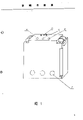
Fig. 1 is a casing structure schematic diagram of the present utility model.
Fig. 2 is an electric theory diagram of the present utility model.
Fig. 3 is the utility model circuitry figure.
Fig. 4 is this practicality self power circuit diagram newly batch.
The utility model is described in further detail for each (accompanying drawing) embodiment of knot below:
The utility model embodiment is made of casing, the movement wiring board, electronic circuit three parts that are installed in the shell.Circuitry is adjusted circuit (6) and is formed by three-phase current detection amplifying circuit (1), computing comparison circuit (2), control executive circuit (3), starting delay circuit (4), failure indicating circuit (5), definite value.Detect the electric current mutual inductance CT in the amplifying circuit (1)
1, CT
2, CT
3With connect operational amplifier A respectively after the three phase mains coupling
1, A
2, A
3Input, the voltage signal with the main circuit current proportion relation that obtains is amplified A
1, A
2, A
3Output divide two parts inputs computing comparison circuit (2), wherein a part is through D
1, D
2, D
3, C
6, C
7, R
14Be divided into after the three phase half wave rectification filtering three the tunnel, the one tunnel with comparator A
7The comparison signal input join, compare the output signal that the back is judged as overload with set-point, when motor overload, this signal numerically will be above set-point, circuit output high potential promotes to control executive circuit (3); Two the tunnel with comparator A
6The reference signal input join, detect reference value with three-phase mean value as degree of unbalance; Three the tunnel then with starting delay circuit (4) in controllable silicon KP
1Join, as the triggering signal of delay circuit (4).Another road is through load resistance R
7, R
8, R
9Be divided into two-way after taking out the three-phase resultant vector by the Y point, the one tunnel with comparator A
5The comparison signal input join, compare the output signal that the back is judged as the phase failure with set-point, when the phase failure takes place, three-phase synthesized voltage vector on the Y point is the voltage opposite with certain phase place of the phase failure, relatively export high potential in the back with this voltage and set-point, promote control executive circuit (3); Another route amplifier A
4Amplify after D
4Rectification and C
4, C
5, R
13Be connected to comparator A after the filtering
6The comparison signal input, as the integrated signal of three-phase imbalance and other fault and three-phase mean value relatively, when degree of unbalance surpassed 10%, this voltage will be above the three-phase average voltage, comparator A
6Upset, the output high potential promotes control executive circuit (3).Overload comparator A
7With phase failure comparator A
5The reference signal input join with M point and the N point that definite value is adjusted in the circuit (6) respectively.Three comparator A in the computing comparison circuit (2)
5, A
6, A
7Output be divided into two-way, lead up to diode D
5, D
6, D
7Join with the time-delay inverter in control executive circuit (3), as the signal that promotes control executive circuit (3), another road respectively with failure diagnosis indicating circuit (5) in three controllable silicon KP
2, KP
3, KP
4Join.Control executive circuit (3) is by time-delay inverter, manual reset circuit, driving ic chip
3, relay J, main contactor form comparator A
5, A
6, A
7In output high potential, then a D are arranged
5, D
6, D
7In one with conducting, through BG
1, C
8, R
17, R
18, R
19After the time-delay inverter of forming, the output electronegative potential makes the relay J adhesive, and the control master controller cuts off main circuit current, owing to IC this moment
36 pin are through resistance R
20Ground connection, its current potential are less than 2/3 V+, so circuit will keep exporting the state of high potential, and button B and resistance R
20Form manual reset circuit, after pressing this button, IC
36 pin are power supply potential, and promptly high potential makes IC
3Reset, 3 pin output electronegative potential relay J discharges.Delay circuit (4) is by the normally-closed contact of button B, controllable silicon KP
1, amplifier A
8, C
10And R
22, W
1Form A
8, C
10, W
1Form integrating circuit, its output and the driving ic chip of controlling in the executive circuit (3)
34 pin join, and the D point that the in-phase input end of integrator and definite value are adjusted in the circuit (6) joins.When electric motor starting, named a person for a particular job trigger voltage output of Q makes controllable silicon KP
1Conducting, integrating circuit will obtain a step input voltage, after the integrating circuit time-delay, put IC by R point output high potential
34 pin (reset terminal), when just starting, the R end will be an electronegative potential, make IC
3Wait to reset, after starting process finished, the R end rose to high potential, at this moment IC
3Enter operating state.Failure diagnosis indicating circuit (5) is by controllable silicon KP
2, KP
3, KP
4, light-emitting diode D
9, D
10, D
11, resistance R
24, R
25, R
26Form.KP
2, KP
3, KP
4Output and control executive circuit (3) in IC
37 pin join.By comparator A
5, A
6, A
7Three triggering signals of output are delivered to KP respectively
2, KP
3, KP
4, when one of them has positive voltage output, corresponding controllable silicon conducting, the light-emitting diode conducting indicates the source of failure, finishes fault diagnosis functions, characteristic and IC that this circuit utilizes silicon control zero-cross to turn-off
37 pin carry out self-insurance, have only IC
3After the action, KP
2, KP
3, KP
4Could conducting, in case conducting then must rely on IC
3Reset and just can make it to reset.Definite value is adjusted circuit (6) by resistance R
27, R
28, R
29Adjust resistance W
2, diode D
12, D
13Form.Adjust W
1, can adjust delay time, adjust W
2The setting value of the phase failure, overload protection can be adjusted, the size of institute's control load can be adjusted.
Self power supply of the utility model embodiment adopts the power supply of being made up of circuit shown in Figure 9.
The utility model shell side basifacial is provided with three-phase power line feedthrough hole (7), the three-phase power line of motor respectively thus three holes pass, have current setting to adjust time-delay adjustment button (10) and failure diagnosis indicator light (11) in button (8), hand-reset button (9) and the starting delay circuit above.
Claims (7)
1, a kind of multi-functional electric motor protecting device; comprise casing, movement wiring board, it is characterized in that the combination that circuitry is adjusted circuit based on three-phase current detection amplifying circuit, computing comparison circuit, control executive circuit, starting delay circuit, failure diagnosis indicating circuit, definite value constitutes.
2, multi-functional electric motor protecting device according to claim 1 is characterized in that the current transformer CT in the big circuit of detection side
1, CT
2.CT
3With connect operational amplifier A respectively after the three phase mains coupling
1, A
2, A
3Input, its output divides two-way input computing comparison circuit, wherein one the tunnel after three phase half wave rectification filtering, be divided into three the tunnel, the one tunnel with overload comparator A
7The comparison signal input join, the two tunnel with degree of balance detection comparator A
6The reference signal input join, the three tunnel then with starting delay circuit in controllable silicon KP
1Join; Another route threephase load resistance R
7, R
8, R
9Be divided into two-way after taking out the three-phase resultant vector, the one tunnel with phase failure comparator A
5Phase failure signal input part join another route A
4Amplify after D
4, C
4, C
5, R
13With degree of balance detection comparator A
6The comparison signal input join overload comparator A
7With phase failure comparator A
5The reference signal input join with M point and the N point that definite value is adjusted in the circuit respectively.
3, multi-functional electric motor protecting device according to claim 1 is characterized in that three comparator A in the computing comparison circuit
5, A
6, A
7Output be divided into two-way, lead up to triode D
5, D
6, D
7Join with the time-delay inverter of control in the executive circuit, another road respectively with the failure diagnosis indicating circuit in three controllable silicon KP
2, KP
3, KP
4Join.
4, multi-functional electric motor protecting device according to claim 1 is characterized in that controlling executive circuit by time-delay inverter, manual reset circuit, driving ic chip
3, relay J, main contactor constitute.
5, multi-functional electric motor protecting device according to claim 1 is characterized in that normally-closed contact, the controllable silicon KP of starting delay circuit by button B
1, amplifier A
8, C
10And R
22, W
1Form A
8, C
10, W
1Form integrating circuit, its output and the driving ic chip of controlling in the executive circuit
34 pin join, the D point that the in-phase input end of integrator and definite value are adjusted in the circuit joins.
6, multi-functional electric motor protecting device according to claim 1 is characterized in that the failure diagnosis indicating circuit is by controllable silicon KP
2, KP
3, KP
4, light-emitting diode D
9, D
10, D
11, resistance R
24, R
25, R
26Form three controllable silicon KP
2, KP
3, KP
4Output and the driving ic chip of control in the executive circuit
37 pin join.
7, multi-functional electric motor protecting device according to claim 1 is characterized in that definite value adjustment circuit is by resistance R
27, R
28, R
29, adjustable resistance W
2, diode D
12, D
13Form.
Priority Applications (1)
| Application Number | Priority Date | Filing Date | Title |
|---|---|---|---|
| CN 92222568 CN2131237Y (en) | 1992-05-23 | 1992-05-23 | Multifunctional protector for motor |
Applications Claiming Priority (1)
| Application Number | Priority Date | Filing Date | Title |
|---|---|---|---|
| CN 92222568 CN2131237Y (en) | 1992-05-23 | 1992-05-23 | Multifunctional protector for motor |
Publications (1)
| Publication Number | Publication Date |
|---|---|
| CN2131237Y true CN2131237Y (en) | 1993-04-28 |
Family
ID=33768888
Family Applications (1)
| Application Number | Title | Priority Date | Filing Date |
|---|---|---|---|
| CN 92222568 Expired - Fee Related CN2131237Y (en) | 1992-05-23 | 1992-05-23 | Multifunctional protector for motor |
Country Status (1)
| Country | Link |
|---|---|
| CN (1) | CN2131237Y (en) |
Cited By (1)
| Publication number | Priority date | Publication date | Assignee | Title |
|---|---|---|---|---|
| CN114089187A (en) * | 2021-11-29 | 2022-02-25 | 中车大连机车车辆有限公司 | A monitoring and analysis method based on three-phase unbalance of AC motor of diesel locomotive |
-
1992
- 1992-05-23 CN CN 92222568 patent/CN2131237Y/en not_active Expired - Fee Related
Cited By (1)
| Publication number | Priority date | Publication date | Assignee | Title |
|---|---|---|---|---|
| CN114089187A (en) * | 2021-11-29 | 2022-02-25 | 中车大连机车车辆有限公司 | A monitoring and analysis method based on three-phase unbalance of AC motor of diesel locomotive |
Similar Documents
| Publication | Publication Date | Title |
|---|---|---|
| CN118209915B (en) | Self-detection system for life end of ground fault device | |
| CN2131237Y (en) | Multifunctional protector for motor | |
| CN217133317U (en) | Detection circuit of leakage protector | |
| CN203026915U (en) | Intelligent type low-voltage motor protector | |
| CN212180906U (en) | A three-phase live indicating circuit | |
| CN2133081Y (en) | Multifunction protector for three-phase motor | |
| JP3448325B2 (en) | Islanding detection method for distributed power supply equipment | |
| CN212518380U (en) | Three-phase power failure and leakage tripping switch | |
| KR100610258B1 (en) | Intelligent power automatic recovery system | |
| CN220019708U (en) | Intelligent electric safety protector | |
| CN111969570B (en) | An F-type residual current detection and protection device | |
| CN210957770U (en) | Leakage protection circuit | |
| CN221767881U (en) | Multi-unit protector for three-phase motor | |
| CN214100836U (en) | Four-pole circuit breaker integrating leakage, phase loss and undervoltage protection | |
| CN223502632U (en) | An elevator energy feedback monitoring system | |
| CN113013836A (en) | Leakage protection circuit | |
| CN216387310U (en) | Three-machine brushless excitation generator rotating diode fault detection circuit | |
| CN114069555B (en) | Three-phase power failure and leakage tripping switch | |
| CN2193614Y (en) | Protector for motor | |
| CN215066992U (en) | Comprehensive protector for microcomputer | |
| CN202721434U (en) | Crane protector | |
| CN2175480Y (en) | Protective arrangement for domestic electricity use | |
| CN2312537Y (en) | Phase interruption and over current protective arrangement for electric machine | |
| CN109578206A (en) | A kind of control device of autonomous lateral deviation blower | |
| CN2396557Y (en) | Multifunctional protector for motor and speed reducer |
Legal Events
| Date | Code | Title | Description |
|---|---|---|---|
| C14 | Grant of patent or utility model | ||
| GR01 | Patent grant | ||
| C19 | Lapse of patent right due to non-payment of the annual fee | ||
| CF01 | Termination of patent right due to non-payment of annual fee |