CN213276830U - Automatic medicine vending machine - Google Patents
Automatic medicine vending machine Download PDFInfo
- Publication number
- CN213276830U CN213276830U CN202120862473.8U CN202120862473U CN213276830U CN 213276830 U CN213276830 U CN 213276830U CN 202120862473 U CN202120862473 U CN 202120862473U CN 213276830 U CN213276830 U CN 213276830U
- Authority
- CN
- China
- Prior art keywords
- goods
- guide rail
- vending machine
- rotating body
- transverse guide
- Prior art date
- Legal status (The legal status is an assumption and is not a legal conclusion. Google has not performed a legal analysis and makes no representation as to the accuracy of the status listed.)
- Active
Links
- 239000003814 drug Substances 0.000 title claims abstract description 70
- 230000007246 mechanism Effects 0.000 claims abstract description 56
- 229940079593 drug Drugs 0.000 claims description 17
- 238000010276 construction Methods 0.000 claims 1
- 239000007788 liquid Substances 0.000 abstract description 5
- 238000000034 method Methods 0.000 abstract description 4
- 230000001771 impaired effect Effects 0.000 abstract description 3
- 230000008569 process Effects 0.000 abstract description 3
- 235000017166 Bambusa arundinacea Nutrition 0.000 description 4
- 235000017491 Bambusa tulda Nutrition 0.000 description 4
- 241001330002 Bambuseae Species 0.000 description 4
- 235000015334 Phyllostachys viridis Nutrition 0.000 description 4
- 239000011425 bamboo Substances 0.000 description 4
- 238000009434 installation Methods 0.000 description 3
- 238000010586 diagram Methods 0.000 description 2
- 239000000825 pharmaceutical preparation Substances 0.000 description 2
- 229940127557 pharmaceutical product Drugs 0.000 description 2
- 230000001174 ascending effect Effects 0.000 description 1
- 230000009286 beneficial effect Effects 0.000 description 1
- 239000002775 capsule Substances 0.000 description 1
- 230000008859 change Effects 0.000 description 1
- 239000011521 glass Substances 0.000 description 1
- 230000006872 improvement Effects 0.000 description 1
- 239000000463 material Substances 0.000 description 1
- 230000004048 modification Effects 0.000 description 1
- 238000012986 modification Methods 0.000 description 1
- 239000002674 ointment Substances 0.000 description 1
- 230000000087 stabilizing effect Effects 0.000 description 1
- 239000006188 syrup Substances 0.000 description 1
- 235000020357 syrup Nutrition 0.000 description 1
Images


Landscapes
- Vending Machines For Individual Products (AREA)
Abstract
The application provides an automatic medicine vending machine belongs to the automatic vending equipment field. The automatic medicine vending machine comprises a cabinet body, a goods shelf, a vertical guide rail, a transverse guide rail and a goods taking mechanism, wherein the goods shelf is over against a show window of the cabinet body and is provided with a plurality of goods storage grooves; the vertical guide rail is positioned at one side of the show window and is connected with the cabinet body; the transverse guide rail is positioned between the goods shelf and the show window, is connected with the vertical guide rail and can move along the vertical guide rail; the goods taking mechanism is connected with the transverse guide rail and can move along the transverse guide rail. When using automatic medicine vending machine to purchase goods, get goods mechanism and can follow the transverse guide removal, and the transverse guide can follow vertical guide removal again, thereby will get goods mechanism and remove the stock tank department at the goods place that needs purchase and get goods, get goods mechanism and remove the mouth of getting goods of automatic medicine vending machine again, take the goods away by customer, the medicine can not receive the impact in the whole process, the impaired of medicine has been avoided, thereby can carry out selling of liquid medicine.
Description
Technical Field
The application relates to the field of automatic vending equipment, in particular to an automatic medicine vending machine.
Background
The automatic vending machine is convenient to use and simple to maintain, and is applied to a plurality of places.
There are many kinds of goods sold by vending machines, and some vending machines are used to sell medicines, such as capsule medicines and external ointments, which are common in life. Such pharmaceutical products have in common that they do not get damaged when falling from the goods shelf of the vending machine to the access opening.
Liquid medicines, such as syrup, aqua lonicerae, and the like, are widely used medicines, and almost never appear in automatic vending machines, because the medicines are often made of fragile materials such as glass, and the containers cannot bear the impact of falling from a goods shelf to a goods taking opening and are easy to damage, so that a large quantity of medicines cannot be sold through the automatic vending machines.
SUMMERY OF THE UTILITY MODEL
The embodiment of the application provides an automatic medicine vending machine, can make things convenient for selling of the medicine of liquid class, reduces the possibility of medicine damage. The technical scheme is as follows:
the embodiment of the application provides an automatic medicine vending machine, which comprises a cabinet body, a goods shelf, a vertical guide rail, a transverse guide rail and a goods taking mechanism, wherein the goods shelf, the vertical guide rail, the transverse guide rail and the goods taking mechanism are all positioned in the cabinet body;
the goods shelf is opposite to the show window of the cabinet body and is provided with a plurality of goods storage grooves;
the vertical guide rail is positioned on one side of the show window and is connected with the cabinet body;
the transverse guide rail is positioned between the goods shelf and the show window, is connected with the vertical guide rail and can move along the vertical guide rail;
the goods taking mechanism is connected with the transverse guide rail and can move along the transverse guide rail.
Optionally, the goods taking mechanism comprises a base, a cover, a tray, a vertical telescopic rod, a rotating body and a motor;
the base is connected with the transverse guide rail;
the cover is cylindrical and is positioned below the base, the top end of the cover is connected with the base, and a goods inlet is formed in one side, close to the goods shelf, of the cover;
the tray is positioned below the housing, one end of the vertical telescopic rod is connected with the housing, and the other end of the vertical telescopic rod is connected with the tray;
the rotating body is positioned in the housing and is coaxially connected with the housing, the rotating body is columnar, and the outer side wall of the rotating body is provided with an accommodating groove which extends to the bottom surface of the rotating body along the axial direction of the rotating body;
the motor is connected with the housing and used for driving the rotating body to rotate.
Optionally, the accommodating groove is provided in plurality, and the plurality of accommodating grooves are distributed at intervals in the circumferential direction of the rotating body.
Optionally, the goods taking mechanism further comprises an installation shaft, the installation shaft is located in the housing and connected with the housing, and the rotating body is coaxially sleeved outside the installation shaft.
Optionally, the bottom end of the mounting shaft has an outer flange.
Optionally, a first gear is coaxially connected to the top end of the rotating body, a second gear is connected to the rotating shaft of the motor, and the second gear is engaged with the first gear.
Optionally, still include and get a goods section of thick bamboo, get a goods section of thick bamboo and be located transverse guide below, and with the cabinet body links to each other, the bottom of getting a goods section of thick bamboo is sealed, and the top has the opening, the open-ended diameter is greater than the diameter of tray, the lateral wall of getting a goods section of thick bamboo has the goods export, the goods export with the mouth of getting goods of the cabinet body is relative.
Optionally, the housing is a transparent structure.
Optionally, the shelf comprises a push plate and a pushing mechanism, the push plate and the pushing mechanism are both located in the storage groove, and the pushing mechanism is located on one side of the push plate away from the showcase.
Optionally, the cabinet body has a payment device therein, the payment device being located at one side of the shop window, the payment device including at least one of a coin-in device and an electronic payment device.
The beneficial effects brought by the technical scheme provided by the embodiment of the application at least comprise:
through set up vertical guide and transverse guide in the cabinet body, it gets goods mechanism to set up on transverse guide, when using automatic vending machine of medicine to purchase the goods, it can follow the transverse guide and remove to get goods mechanism, and transverse guide can follow vertical guide and remove again, thereby will get goods mechanism and remove the stock groove department at the goods place that needs the purchase and get goods, it removes the mouth of getting goods of automatic vending machine of medicine again to get goods mechanism, take away the goods by customer, the medicine can not receive the impact in the whole process, the impaired of medicine has been avoided, thereby can carry out selling of liquid medicine.
Drawings
In order to more clearly illustrate the technical solutions in the embodiments of the present application, the drawings needed to be used in the description of the embodiments are briefly introduced below, and it is obvious that the drawings in the following description are only some embodiments of the present application, and it is obvious for those skilled in the art to obtain other drawings based on these drawings without creative efforts.
Fig. 1 is a schematic structural diagram of a pharmaceutical vending machine according to an embodiment of the present application;
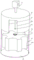
fig. 2 is an exploded schematic view of a pickup mechanism according to an embodiment of the present disclosure;
fig. 3 is an exploded schematic view of a pickup mechanism according to an embodiment of the present disclosure.
Detailed Description
To make the objects, technical solutions and advantages of the present application more clear, embodiments of the present application will be described in further detail below with reference to the accompanying drawings.
Unless defined otherwise, technical or scientific terms used herein shall have the ordinary meaning as understood by one of ordinary skill in the art to which this application belongs. The use of "first," "second," "third," and similar terms in the description and claims of this application do not denote any order, quantity, or importance, but rather the terms are used to distinguish one element from another. Also, the use of the terms "a" or "an" and the like do not denote a limitation of quantity, but rather denote the presence of at least one. The word "comprise" or "comprises", and the like, means that the element or item listed before "comprises" or "comprising" covers the element or item listed after "comprising" or "comprises" and its equivalents, and does not exclude other elements or items. The terms "connected" or "coupled" and the like are not restricted to physical or mechanical connections, but may include electrical connections, whether direct or indirect. "upper", "lower", "left", "right", and the like are used merely to indicate relative positional relationships, which may also change accordingly when the absolute position of the object being described changes.
Fig. 1 is a schematic structural diagram of a pharmaceutical product vending machine according to an embodiment of the present application. As shown in fig. 1, the automatic medicine vending machine includes a cabinet 10, a goods shelf 20, a vertical rail 30, a transverse rail 40, and a goods taking mechanism 50. The cargo rack 20, the vertical guide rails 30, the transverse guide rails 40 and the pickup mechanism 50 are all located within the cabinet 10.
The shelf 20 faces the showcase 10a of the cabinet 10, and the shelf 20 has a plurality of storage slots 21.
The vertical rail 30 is located at one side of the showcase 10a, and is connected to the cabinet 10. Transverse rails 40 are located between the shelves 20 and the showcase 10a and are connected to the vertical rails 30, and the transverse rails 40 can move along the vertical rails 30. The pickup mechanism 50 is coupled to the cross rail 40, and the pickup mechanism 50 is movable along the cross rail 40.
Through set up vertical guide and transverse guide in the cabinet body, it gets goods mechanism to set up on transverse guide, when using automatic vending machine of medicine to purchase the goods, it can follow the transverse guide and remove to get goods mechanism, and transverse guide can follow vertical guide and remove again, thereby will get goods mechanism and remove the stock groove department at the goods place that needs the purchase and get goods, it removes the mouth of getting goods of automatic vending machine of medicine again to get goods mechanism, take away the goods by customer, the medicine can not receive the impact in the whole process, the impaired of medicine has been avoided, thereby can carry out selling of liquid medicine.
As shown in fig. 1, the cargo rack 20 includes a push plate 22 and a push mechanism 23. Both the push plate 22 and the pushing mechanism 23 are located in the storage tank 21, and the pushing mechanism 23 is located on the side of the push plate 22 away from the showcase 10 a.
When the picking mechanism 50 moves to the front of the storage slot 21, the pushing plate 22 is pushed by the pushing mechanism 23, and a bottle of medicine closest to the picking mechanism 50 is pushed into the picking mechanism 50.
As shown in fig. 1, the cabinet 10 has a payment device 70 therein, and the payment device 70 is located at one side of the showcase 10 a. The payment device 70 includes at least one of a coin-in device 71 and an electronic payment device 72. When the user purchases the medicine, the user can select a proper mode to pay, and the medicine is convenient for the user to use.
Fig. 2 and fig. 3 are schematic exploded structural views of a pickup mechanism according to an embodiment of the present disclosure. As shown in fig. 2 and 3, the pickup mechanism 50 includes a base 51, a cover 52, a tray 53, a vertically telescopic rod 54, a rotating body 55, and a motor 56.
The base 51 is connected to the cross rail 40. The cover 52 is cylindrical and is located below the base 51, and the top end of the cover is connected to the base 51, and a cargo entrance 52a is formed at one side of the cover 52 close to the cargo rack 20. The tray 53 is positioned below the housing 52, and one end of the vertical telescopic rod 54 is connected with the housing 52, and the other end is connected with the tray 53.
The rotating body 55 is located in the housing 52 and coaxially connected to the housing 52, the rotating body 55 is in a cylindrical shape, and an outer side wall of the rotating body 55 has a receiving groove 55a, and the receiving groove 55a extends to a bottom surface of the rotating body 55 along an axial direction of the rotating body 55. The motor 56 is connected to the housing 52 for driving the rotation of the rotating body 55.
When the picking mechanism 50 picks up the medicine, the picking mechanism 50 moves to the goods inlet 52a to align with the storage slot 21 for storing the needed medicine, the goods shelf 20 feeds the medicine into the holding groove 55a opposite to the goods inlet 52a from the goods inlet 52a, and the rotating body 55 rotates again to make the holding groove 55a staggered with the goods inlet 52a, so as to avoid the dropped medicine, thereby smoothly picking up the medicine. When the goods taking mechanism 50 moves to the goods taking opening 10b of the automatic medicine vending machine, the vertical telescopic rod 54 is extended, the tray 53 is far away from the housing 52 and the rotating body 55, the medicine is left on the tray 53, and after the distance between the tray 53 and the housing 52 reaches a certain value, the user can insert a hand from the goods taking opening 10b to take the medicine on the tray 53.
As shown in fig. 1, the pharmaceutical vending machine further includes a take-out drum 60. The goods taking barrel 60 is located below the transverse guide rail 40 and connected with the cabinet 10, the bottom end of the goods taking barrel 60 is closed, the top end of the goods taking barrel 60 is provided with an opening 60a, the diameter of the opening 60a is larger than that of the tray 53, the side wall of the goods taking barrel 60 is provided with a goods outlet 60b, and the goods outlet 60b is opposite to the goods taking opening 10b of the cabinet 10.
After the medicine is taken out, the goods taking mechanism 50 firstly moves to a position right above the goods taking barrel 60 and keeps still, then is extended by the vertical telescopic rod 54, the tray 53 enters the goods taking barrel 60 from the top of the goods taking barrel 60 and gradually descends to the position of the goods outlet 60b, and a user can stretch hands into the goods taking opening 10b of the cabinet body 10 and take the medicine on the tray 53 out of the goods outlet 60 b.
Or after the medicine is taken by the goods taking mechanism 50, the goods taking mechanism 50 moves to a position right above the goods taking barrel 60, then the transverse guide rail 40 descends along the vertical guide rail 30, the goods taking mechanism 50 enters the goods taking barrel 60 from the top of the goods taking barrel 60 until the position of the tray 53 is lower than the goods outlet 60b, then the transverse guide rail 40 is controlled to ascend along the vertical guide rail 30, the vertical telescopic rod 54 is controlled to extend, the cover 52 and the rotating body 55 ascend along the transverse guide rail 40, and the medicine is left on the tray 53. The medicine on the tray 53 is then taken out from the goods outlet 60b by the user. When the cross rail 40 ascends along the vertical rail 30, the tray 53 is kept stationary with respect to the cargo outlet 60b by controlling the speed of the cross rail 40 ascending along the vertical rail 30 and the speed of the extension of the vertically extendable rod 54. This enables the medicine on the tray 53 to be placed more smoothly, further reducing the possibility of breakage of the medicine.
As shown in fig. 2, the accommodating groove 55a is plural, and the plural accommodating grooves 55a are spaced apart from each other in the circumferential direction of the rotating body 55.
The user usually purchases a plurality of medicines at a time when purchasing the medicines, and during the purchase, each time one medicine is fed into one of the receiving grooves 55a, the rotator 55 rotates once to align the next receiving groove 55a into which the medicine is not yet fed with the goods inlet 52a to prepare for receiving the next medicine fed from the goods inlet 52 a. Through a plurality of holding tanks 55a, a plurality of medicines are conveniently bought once to holding tank 55a can be with the medicine restriction in a less space, avoid bumping between the medicine, further reduced the medicine in the damaged possibility of purchase in-process.
As shown in fig. 2, the pickup mechanism 50 further includes a mounting shaft 57, the mounting shaft 57 being located in the housing 52 and connected to the housing 52. The rotating body 55 is coaxially sleeved outside the mounting shaft 57.
The rotating body 55 is supported by the mounting shaft 57, so that the rotating body 55 can be stably mounted in the housing 52, and can be stably rotated about the mounting shaft 57 by the driving of the motor 56.
As shown in fig. 2, the bottom end of the mounting shaft 57 has an outer flange 571.
The outer flange 571 supports an end of the rotator 55 and axially restricts the rotator 55, thereby further stabilizing the mounting of the rotator 55.
As shown in fig. 2, a first gear 551 is coaxially connected to the tip of the rotating body 55. As shown in fig. 3, a second gear 561 is connected to a rotation shaft of the motor 56, and the second gear 561 is engaged with the first gear 551.
The torque is transmitted through the gear to smoothly rotate the rotating body 55. The motor 56 may be a stepping motor, which facilitates accurate control of the angle of the rotating body 55 at each rotation.
Optionally, the housing 52 is a transparent structure.
A transparent cover 52 is provided to facilitate the user's viewing of the medication in the picking mechanism 50. The rotating body 55 may be a transparent structure.
The above description is only exemplary of the present application and should not be taken as limiting, as any modification, equivalent replacement, or improvement made within the spirit and principle of the present application should be included in the protection scope of the present application.
Claims (10)
1. An automatic medicine vending machine is characterized by comprising a cabinet body (10), a goods shelf (20), a vertical guide rail (30), a transverse guide rail (40) and a goods taking mechanism (50), wherein the goods shelf (20), the vertical guide rail (30), the transverse guide rail (40) and the goods taking mechanism (50) are all positioned in the cabinet body (10);
the goods shelf (20) is opposite to the show window (10 a) of the cabinet body (10), and the goods shelf (20) is provided with a plurality of storage grooves (21);
the vertical guide rail (30) is positioned at one side of the show window (10 a) and is connected with the cabinet body (10);
the transverse guide rail (40) is positioned between the goods shelf (20) and the show window (10 a), is connected with the vertical guide rail (30) and can move along the vertical guide rail (30);
the goods taking mechanism (50) is connected with the transverse guide rail (40) and can move along the transverse guide rail (40).
2. The automatic drug vending machine according to claim 1, wherein the pick-up mechanism (50) comprises a base (51), a casing (52), a tray (53), a vertically telescopic rod (54), a rotating body (55) and a motor (56);
the base (51) is connected with the transverse guide rail (40);
the cover (52) is cylindrical and is positioned below the base (51), the top end of the cover is connected with the base (51), and a goods inlet (52 a) is formed in one side, close to the goods shelf (20), of the cover (52);
the tray (53) is positioned below the housing (52), one end of the vertical telescopic rod (54) is connected with the housing (52), and the other end of the vertical telescopic rod is connected with the tray (53);
the rotating body (55) is positioned in the housing (52) and is coaxially connected with the housing (52), the rotating body (55) is columnar, the outer side wall of the rotating body (55) is provided with a containing groove (55 a), and the containing groove (55 a) extends to the bottom surface of the rotating body (55) along the axial direction of the rotating body (55);
the motor (56) is connected with the housing (52) and is used for driving the rotating body (55) to rotate.
3. A drug vending machine according to claim 2, wherein the accommodating groove (55 a) is provided in plural, and the plural accommodating grooves (55 a) are spaced apart from each other in the circumferential direction of the rotary body (55).
4. Drug vending machine according to claim 2, characterized in that the pick-up mechanism (50) further comprises a mounting shaft (57), the mounting shaft (57) being located in the casing (52) and being connected to the casing (52), the rotating body (55) being coaxially fitted over the mounting shaft (57).
5. Pharmaceutical vending machine according to claim 4, characterized in that the bottom end of the mounting shaft (57) has an outer flange (571).
6. The automatic drug vending machine according to claim 4, wherein a first gear (551) is coaxially connected to a top end of the rotating body (55), a second gear (561) is connected to a rotating shaft of the motor (56), and the second gear (561) is engaged with the first gear (551).
7. The drug vending machine according to any one of claims 2 to 6, further comprising a delivery tube (60), wherein the delivery tube (60) is located below the transverse guide rail (40) and connected to the cabinet (10), the delivery tube (60) is closed at a bottom end and has an opening (60 a) at a top end, the opening (60 a) has a diameter larger than that of the tray (53), the delivery tube (60) has a side wall with a cargo outlet (60 b), and the cargo outlet (60 b) is opposite to the delivery opening (10 b) of the cabinet (10).
8. Pharmaceutical vending machine according to any one of claims 2 to 6, characterized in that the housing (52) is of transparent construction.
9. Pharmaceutical vending machine according to any one of claims 1 to 6, characterized in that the shelf (20) comprises a push plate (22) and a pushing mechanism (23), the push plate (22) and the pushing mechanism (23) being both located in the storage trough (21), the pushing mechanism (23) being located on the side of the push plate (22) remote from the showcase (10 a).
10. Drug vending machine according to any one of claims 1 to 6, characterized in that the cabinet (10) has a payment device (70) therein, the payment device (70) being located at one side of the showcase (10 a), the payment device (70) comprising at least one of a coin-operated device (71) and an electronic payment device (72).
Priority Applications (1)
| Application Number | Priority Date | Filing Date | Title |
|---|---|---|---|
| CN202120862473.8U CN213276830U (en) | 2021-04-25 | 2021-04-25 | Automatic medicine vending machine |
Applications Claiming Priority (1)
| Application Number | Priority Date | Filing Date | Title |
|---|---|---|---|
| CN202120862473.8U CN213276830U (en) | 2021-04-25 | 2021-04-25 | Automatic medicine vending machine |
Publications (1)
| Publication Number | Publication Date |
|---|---|
| CN213276830U true CN213276830U (en) | 2021-05-25 |
Family
ID=75955144
Family Applications (1)
| Application Number | Title | Priority Date | Filing Date |
|---|---|---|---|
| CN202120862473.8U Active CN213276830U (en) | 2021-04-25 | 2021-04-25 | Automatic medicine vending machine |
Country Status (1)
| Country | Link |
|---|---|
| CN (1) | CN213276830U (en) |
-
2021
- 2021-04-25 CN CN202120862473.8U patent/CN213276830U/en active Active
Similar Documents
| Publication | Publication Date | Title |
|---|---|---|
| US6328180B1 (en) | Apparatus and method for vending products | |
| EP1552805B1 (en) | Device for dispensing medicine | |
| JP5352469B2 (en) | How to dispense products from vending machine shelves | |
| US6682289B1 (en) | Dispensing apparatus and method of using same | |
| KR100415587B1 (en) | Tablet packing apparatus | |
| US6513677B1 (en) | Apparatus and method for vending products | |
| CN107958543B (en) | Automatic get cargo aircraft | |
| US20090076650A1 (en) | Article storage and retrieval apparatus and vending machine | |
| AU746873B2 (en) | Dispensing apparatus and method of using same | |
| CA2467739A1 (en) | Machine and methods for vending articles | |
| KR20100023797A (en) | Tablet filler device | |
| US4671426A (en) | Automatic article dispenser using screw-driven mobile trays | |
| CN213276830U (en) | Automatic medicine vending machine | |
| CN209070637U (en) | A kind of automatic mineral water of simplicity is for cargo aircraft | |
| US2193211A (en) | Dispensing apparatus | |
| JP3373503B2 (en) | Drug packaging device | |
| JP2009023844A (en) | Approximately cylindrical article put-out device | |
| CN210466540U (en) | Self-service medicine instrument dispensing device | |
| JPH11314601A (en) | Medicine packaging device | |
| JPH10167452A (en) | Delivery device for nearly cylindrical article and its delivery method | |
| KR100746584B1 (en) | vending machine | |
| KR102789136B1 (en) | Liquor vending machine | |
| JP4243301B2 (en) | Dispensing device for substantially cylindrical article | |
| ES2376441B1 (en) | AUTOMATIC DISPENSER Kiosk APPLICABLE AS A POINT OF SALE FOR THE SUPPLY OF CASTLE CAPSULES, IN SPECIAL FOR THE PREPARATION OF DRINKS. | |
| CN217787812U (en) | Single-bag product selling device |
Legal Events
| Date | Code | Title | Description |
|---|---|---|---|
| GR01 | Patent grant | ||
| GR01 | Patent grant | ||
| CP01 | Change in the name or title of a patent holder | ||
| CP01 | Change in the name or title of a patent holder |
Address after: 430035 No.03, 7th floor, building C, China Merchants Jiangwan International Center, Gutian 2nd Road, Qiaokou District, Wuhan City, Hubei Province Patentee after: Wuhan Jiagu peptide Biotechnology Co.,Ltd. Address before: 430035 No.03, 7th floor, building C, China Merchants Jiangwan International Center, Gutian 2nd Road, Qiaokou District, Wuhan City, Hubei Province Patentee before: Wuhan Jiagu peptide industry Biotechnology Co.,Ltd. |