Bending device is used in steel strand wires production
Technical Field
The utility model relates to a steel strand wires field especially relates to a bending apparatus is used in steel strand wires production.
Background
The steel strand wires are the steel and iron products that constitute by many steel wires transposition, the galvanized coating can be increased as required on the carbon steel surface, the zinc-aluminum alloy layer, alclad layer, the copper plate, scribble epoxy, when the user uses the steel strand wires, because the irregular characteristic of building, need carry out bending process to the steel strand wires, thereby need use bending apparatus, current bending apparatus is in the use, the bending effect is poor, and the displacement slippage easily appears in the steel strand wires bending process, lead to the bending angle of steel strand wires not up to standard, influence the normal use of user to the steel strand wires.
Therefore, it is necessary to provide a bending apparatus for manufacturing steel strands to solve the above technical problems.
SUMMERY OF THE UTILITY MODEL
The utility model provides a bending apparatus is used in steel strand wires production has solved current bending apparatus in the use, the poor problem of crooked effect.
For solving the technical problem, the utility model provides a pair of bending apparatus is used in steel strand wires production, the power distribution box comprises a box body, the top of box has been bolted the workstation, logical groove has all transversely been seted up to the center department at box and workstation inner chamber top, the positive left side of box has been bolted the controller, the center department in the past of workstation top has bolted the mount to the back in proper order, the inner chamber of mount is provided with fixture, the right side in the past of workstation top has been bolted the leading truck to the back in proper order, the inner chamber lateral transmission of leading truck is connected with steel strand wires, the top of workstation is provided with bending mechanism.
Preferably, fixture includes fixed grip slipper, a screw thread section of thick bamboo, threaded rod, swing handle and removal grip slipper, the bottom of mount inner chamber has bolted connection fixed grip slipper, the top of mount inner chamber is inlayed and is equipped with a screw thread section of thick bamboo, the inner chamber threaded connection of a screw thread section of thick bamboo has the threaded rod, the top of threaded rod is equipped with the swing handle, the bottom of threaded rod is rotated through the bearing and is connected with the removal grip slipper.
Preferably, the bending mechanism comprises a servo motor, a speed reducer, a screw rod, a threaded sleeve, a moving seat, a moving head, a first tensioning adjusting wheel and a second tensioning adjusting wheel, the servo motor is bolted on the right side of the inner cavity of the box body, the speed reducer is bolted on an output shaft of the servo motor, the screw rod is bolted on the left side of the speed reducer, the left side of the screw rod is rotatably connected with the left side of the inner cavity of the box body through a bearing, the threaded sleeve is connected with the surface thread of the screw rod in a threaded manner, the moving seat is bolted on the top of the threaded sleeve, the moving head which is matched with the steel strand in a winding manner is bolted on the top of the moving seat through a through groove, the first tensioning adjusting wheel is rotatably connected on the left side of the top of the workbench from the front to the back in sequence, the second tensioning adjusting wheel is rotatably connected on the left side of the top of the workbench from the front, and one opposite sides of the first tensioning adjusting wheel and the second tensioning adjusting wheel are in transmission connection with the surface of the steel strand.
Preferably, the top and the bottom of the inner cavity of the guide frame are rotatably connected with guide wheels in transmission fit with the steel strands, heat dissipation holes are formed in the periphery of the front face of the box body, and the heat dissipation holes are honeycomb-shaped.
Preferably, a sliding rail is transversely arranged at the center of the bottom of the inner cavity of the box body, a pulley is connected to the inner cavity of the sliding rail in a sliding manner, and the top of the pulley is bolted to the bottom of the threaded sleeve.
Preferably, the top of the inner cavity of the box body is transversely bolted with a sliding column, the surface of the sliding column is slidably connected with a sliding sleeve, and the outer side of the sliding sleeve is embedded with the inner cavity of the movable seat.
Preferably, both sides of the sliding column are sleeved with buffer springs, and one opposite sides of the buffer springs are bolted to the outer side of the sliding sleeve.
Preferably, the controller is connected with the servo motor and the speed reducer through lines.
Compared with the prior art, the utility model provides a pair of bending apparatus is used in steel strand wires production has following beneficial effect:
the utility model provides a bending device for producing steel strands,
1. the utility model discloses a fixed grip slipper, a screw thread section of thick bamboo, the threaded rod, the cooperation of swing handle and removal grip slipper, can compress tightly fixedly to the both ends of steel strand wires, avoid the displacement slippage to appear in the steel strand wires bending process, improve the whole steadiness of steel strand wires, through servo motor, a speed reducer, the lead screw, the thread bush, remove the cooperation of seat and removal head, can drive steel strand wires at the uniform velocity tensile left, force steel strand wires department of bending to form predetermined crooked contained angle, cooperation through first tensioning regulating wheel and second tensioning regulating wheel, can carry out tensioning in advance to steel strand wires and adjust, avoid the uneven displacement that appears of steel strand wires in-process atress, make steel strand wires roll over the bent angle degree and can not reach predetermined standard, thereby strengthen the whole bending effect of steel strand wires.
2. The utility model discloses a leading wheel, can lead to steel strand wires in advance, avoid appearing rocking by a wide margin and skew among the steel strand wires transmission process, through the louvre, can carry out the heat dissipation to the inside heat of box and handle, avoid the high temperature to cause the damage to box internals, through slide rail and pulley, can slide the support bottom the thread bush, avoid the thread bush to remove the in-process and appear rocking and the displacement, improve the stationarity that the thread bush removed, through traveller and sliding sleeve, make the removal seat can steadily slide, further improve the removal steadiness of removal head, through buffer spring, can carry out elasticity spacing to the displacement of sliding sleeve, also improve the uniform velocity nature that the sliding sleeve removed simultaneously.
Drawings
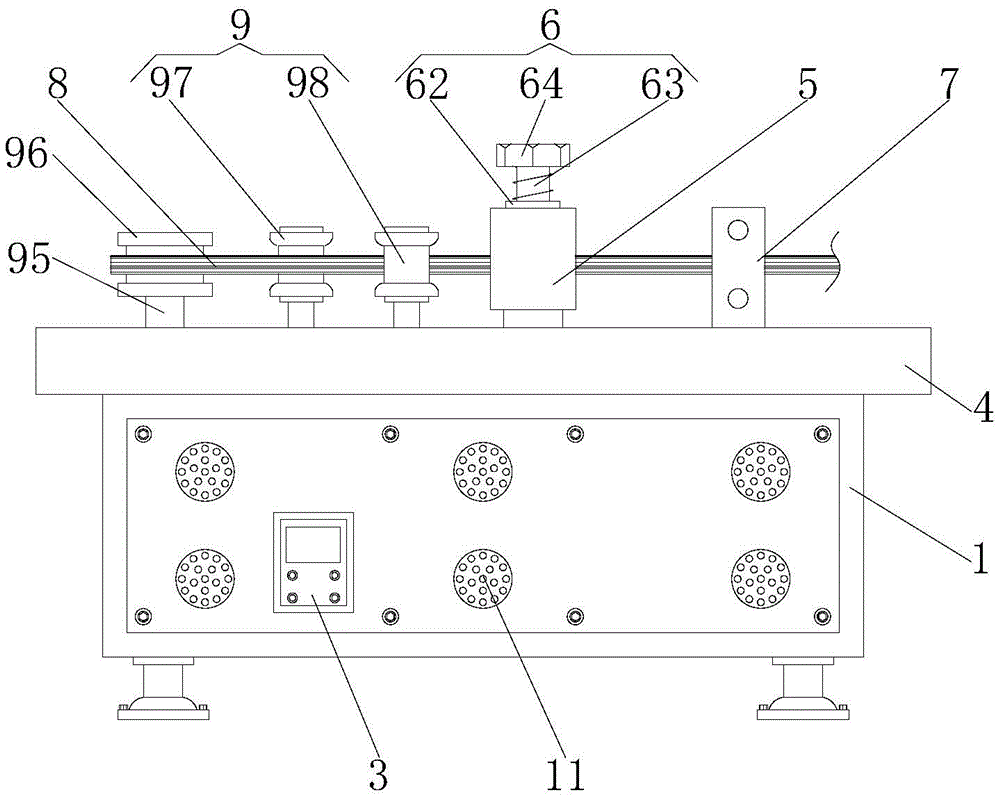
Fig. 1 is a schematic structural diagram of a bending apparatus for producing a steel strand according to a preferred embodiment of the present invention;
FIG. 2 is a top view of the structure of the case shown in FIG. 1;
FIG. 3 is a sectional view of the structure of the case shown in FIG. 1;
FIG. 4 is a side view of the holder of FIG. 1;
fig. 5 is a structural side view of the guide frame shown in fig. 1.
Reference numbers in the figures: 1. a box body; 2. a through groove; 3. a controller; 4. a work table; 5. a fixed mount; 6. a clamping mechanism; 61. fixing the clamping seat; 62. a threaded barrel; 63. a threaded rod; 64. turning a handle; 65. moving the clamping seat; 7. a guide frame; 8. steel strand wires; 9. a bending mechanism; 91. a servo motor; 92. a speed reducer; 93. a screw rod; 94. a threaded sleeve; 95. a movable seat; 96. a moving head; 97. a first tensioning wheel; 98. a second tensioning adjustment wheel; 10. a guide wheel; 11. heat dissipation holes; 12. a slide rail; 13. a pulley; 14. a traveler; 15. a sliding sleeve; 16. a buffer spring.
Detailed Description
The present invention will be further described with reference to the accompanying drawings and embodiments.
Please refer to fig. 1, fig. 2, fig. 3, fig. 4 and fig. 5 in combination, in which fig. 1 is a schematic structural diagram of a bending apparatus for manufacturing a steel strand according to a preferred embodiment of the present invention; FIG. 2 is a top view of the structure of the case shown in FIG. 1; FIG. 3 is a sectional view of the structure of the case shown in FIG. 1; FIG. 4 is a side view of the holder of FIG. 1; fig. 5 is the structural side view of the leading truck shown in fig. 1, a bending apparatus is used in steel strand production, including box 1, box 1's top bolt has workstation 4, logical groove 2 has all transversely been seted up to the center department at box 1 and 4 inner chamber tops of workstation, box 1 positive left side bolt has connected controller 3, the center department at 4 tops of workstation has bolted mount 5 after to in the past in proper order, the inner chamber of mount 5 is provided with fixture 6, the right side at 4 tops of workstation has bolted mount 7 after to in the past in proper order, the inner chamber lateral transmission of leading truck 7 is connected with steel strand 8, the top of workstation 4 is provided with bending mechanism 9.
Fixture 6 includes fixed grip slipper 61, a screw thread section of thick bamboo 62, threaded rod 63, swing handle 64 and removes grip slipper 65, the bottom of 5 inner chambers of mount has bolted fixed grip slipper 61, 5 inner chambers of mount's top is inlayed and is equipped with a screw thread section of thick bamboo 62, the inner chamber threaded connection of a screw thread section of thick bamboo 62 has threaded rod 63, the top of threaded rod 63 is equipped with swing handle 64, the bottom of threaded rod 63 is rotated through the bearing and is connected with removal grip slipper 65, can compress tightly fixedly to the both ends of steel strand wires 8, avoids the displacement slippage to appear in the 8 crooked processes of steel strand wires, improves the whole steadiness of steel strand wires 8.
The bending mechanism 9 comprises a servo motor 91, a speed reducer 92, a screw rod 93, a threaded sleeve 94, a moving seat 95, a moving head 96, a first tensioning adjusting wheel 97 and a second tensioning adjusting wheel 98, the servo motor 91 is bolted on the right side of the inner cavity of the box body 1, the speed reducer 92 is bolted on an output shaft of the servo motor 91, the screw rod 93 is bolted on the left side of the speed reducer 92, the left side of the screw rod 93 is rotatably connected with the left side of the inner cavity of the box body 1 through a bearing, the threaded sleeve 94 is connected on the surface of the screw rod 93 in a threaded manner, the moving seat 95 is bolted on the top of the threaded sleeve 94, the top of the moving seat 95 penetrates through the through groove 2 and is bolted with the moving head 96 which is wound and matched with the steel strand 8, the steel strand 8 can be driven to be stretched leftwards at a constant speed, a preset bending included angle is formed at the bending part of the steel strand 8, the left side at 4 tops of workstation rotates in proper order after to in the past and is connected with second tensioning regulating wheel 98, second tensioning regulating wheel 98 is located the right side of first tensioning regulating wheel 97, first tensioning regulating wheel 97 and second tensioning regulating wheel 98 one side in opposite directions all are connected with steel strand wires 8's surface transmission, can carry out tensioning in advance to steel strand wires 8 and adjust, avoid steel strand wires 8 to bend the displacement of in-process atress inequality appearance, make 8 angle of bending of steel strand wires reach predetermined standard to reinforcing steel strand wires 8's whole bending effect.
The top and the bottom of 7 inner chambers of leading truck all rotate be connected with 8 transmission complex leading wheels 10 of steel strand wires, can lead in advance to steel strand wires 8, avoid 8 transmission in-process of steel strand wires to appear rocking by a wide margin and skew, louvre 11 has all been seted up around the box 1 is positive, louvre 11's shape sets up to honeycomb, can carry out the heat dissipation to 1 inside heat of box and handle, avoids high temperature to cause the damage to 1 internal part of box.
The sliding rail 12 is transversely arranged at the center of the bottom of the inner cavity of the box body 1, the inner cavity of the sliding rail 12 is connected with the pulley 13 in a sliding mode, the top of the pulley 13 is in bolted connection with the bottom of the threaded sleeve 94, the bottom of the threaded sleeve 94 can be supported in a sliding mode, shaking and displacement in the moving process of the threaded sleeve 94 are avoided, and the moving stability of the threaded sleeve 94 is improved.
The top of the inner cavity of the box body 1 is transversely bolted with a sliding column 14, the surface of the sliding column 14 is connected with a sliding sleeve 15 in a sliding manner, the outer side of the sliding sleeve 15 is embedded with the inner cavity of the moving seat 95, so that the moving seat 95 can slide stably, and the moving stability of the moving head 96 is further improved.
Both sides of the sliding column 14 are sleeved with buffer springs 16, one opposite sides of the buffer springs 16 are bolted with the outer side of the sliding sleeve 15, the moving distance of the sliding sleeve 15 can be elastically limited, and the moving speed of the sliding sleeve 15 is improved.
The utility model provides a pair of bending apparatus is used in steel strand wires production's theory of operation as follows:
when the bending device is used, a user passes a steel strand 8 to be bent through the guide wheel 10, the first tensioning adjusting wheel 97, the second tensioning adjusting wheel 98 and the moving head 96 in sequence, the steel strand 8 is positioned on the inner sides of the movable clamping seat 65 and the fixed clamping seat 61, then the user rotates the rotating handle 64 clockwise, the rotating handle 64 drives the threaded rod 63 to rotate downwards in the threaded cylinder 62, the threaded rod 63 drives the movable clamping seat 65 to move downwards, the movable clamping seat 65 and the fixed clamping seat 61 are matched through fixed support of the fixed clamping seat 61, so that the steel strand 8 is clamped and fixed by the movable clamping seat 65 and the fixed clamping seat 61, then the user starts the servo motor 91 and the speed reducer 92 through the controller 3, the servo motor 91 drives the lead screw 93 to rotate forwards at a high speed, the speed reducer 92 adjusts the rotating speed of the lead screw 93 at a constant speed, the pulley 13 slides in the sliding rail 12, so that the lead, the sliding sleeve 15 slides on the surface of the sliding column 14, the threaded sleeve 94 drives the moving head 96 to move leftwards stably through the moving seat 95, and the steel strand 8 is tensioned and adjusted through the first tensioning adjusting wheel 97 and the second tensioning adjusting wheel 98, so that the moving head 96 performs rapid bending operation on the steel strand 8.
Compared with the prior art, the utility model provides a pair of bending apparatus is used in steel strand wires production has following beneficial effect:
the utility model discloses a fixed grip slipper 61, a screw thread section of thick bamboo 62, threaded rod 63, swing handle 64 and the cooperation of removing grip slipper 65, can compress tightly fixedly to the both ends of steel strand wires 8, avoid the displacement slippage to appear in the 8 bending process of steel strand wires, improve the whole steadiness of steel strand wires 8, through servo motor 91, speed reducer 92, lead screw 93, thread bush 94, remove seat 95 and the cooperation of removing head 96, can drive steel strand wires 8 at the uniform velocity tensile left, force steel strand wires 8 department of bending to form predetermined crooked contained angle, cooperation through first tensioning regulating wheel 97 and second tensioning regulating wheel 98, can carry out tensioning in advance to steel strand wires 8 and adjust, avoid the uneven displacement of appearing of the in-process atress of bending of steel strand wires 8, lead to 8 bending angles of steel strand wires to reach predetermined standard, thereby strengthen the whole crooked effect of steel strand wires 8.
The above only is the embodiment of the present invention, not limiting the scope of the present invention, all the equivalent structures or equivalent processes of the present invention are used in the specification and the attached drawings, or directly or indirectly applied to other related technical fields, and the same principle is included in the protection scope of the present invention.