CN213534603U - Automobile front wheel arch structure convenient to locate - Google Patents
Automobile front wheel arch structure convenient to locate Download PDFInfo
- Publication number
- CN213534603U CN213534603U CN202022576392.XU CN202022576392U CN213534603U CN 213534603 U CN213534603 U CN 213534603U CN 202022576392 U CN202022576392 U CN 202022576392U CN 213534603 U CN213534603 U CN 213534603U
- Authority
- CN
- China
- Prior art keywords
- wheel arch
- fluted disc
- sheet metal
- connecting piece
- vehicle
- Prior art date
- Legal status (The legal status is an assumption and is not a legal conclusion. Google has not performed a legal analysis and makes no representation as to the accuracy of the status listed.)
- Expired - Fee Related
Links
- 239000002184 metal Substances 0.000 claims abstract description 50
- 229910052751 metal Inorganic materials 0.000 claims abstract description 50
- 238000010009 beating Methods 0.000 claims abstract description 17
- 238000009434 installation Methods 0.000 claims description 9
- 210000004709 eyebrow Anatomy 0.000 abstract description 12
- 239000004922 lacquer Substances 0.000 abstract description 3
- 230000008878 coupling Effects 0.000 abstract description 2
- 238000010168 coupling process Methods 0.000 abstract description 2
- 238000005859 coupling reaction Methods 0.000 abstract description 2
- 238000000034 method Methods 0.000 description 8
- XEEYBQQBJWHFJM-UHFFFAOYSA-N Iron Chemical compound [Fe] XEEYBQQBJWHFJM-UHFFFAOYSA-N 0.000 description 4
- 238000005034 decoration Methods 0.000 description 4
- 230000002349 favourable effect Effects 0.000 description 4
- 229910052742 iron Inorganic materials 0.000 description 2
- 230000008569 process Effects 0.000 description 2
- 230000004075 alteration Effects 0.000 description 1
- 230000009286 beneficial effect Effects 0.000 description 1
- 238000001125 extrusion Methods 0.000 description 1
- 238000010030 laminating Methods 0.000 description 1
- 238000012986 modification Methods 0.000 description 1
- 230000004048 modification Effects 0.000 description 1
- 238000012856 packing Methods 0.000 description 1
- 239000003973 paint Substances 0.000 description 1
- 230000001737 promoting effect Effects 0.000 description 1
- 230000000087 stabilizing effect Effects 0.000 description 1
- 238000006467 substitution reaction Methods 0.000 description 1
Images


Landscapes
- Vehicle Cleaning, Maintenance, Repair, Refitting, And Outriggers (AREA)
Abstract
The utility model discloses a wheel eyebrow structure before car convenient to location, including vehicle panel beating and fluted disc spread groove, the left side and the wheel eyebrow body coupling of vehicle panel beating, and the inside spring mounting storehouse of having seted up in right side of wheel eyebrow body to the one end of pressure spring is connected to the top surface in spring mounting storehouse, and the top surface of limiting plate is connected to pressure spring's the other end simultaneously, the limiting plate sets up on the wheel eyebrow locating lever, and the top of wheel eyebrow locating lever is provided with the counterpoint fluted disc to the bottom surface and the fluted disc spread groove of counterpoint fluted disc are connected, and the top surface at the sheet metal connection piece is seted up to the fluted disc spread groove simultaneously, sheet metal connection piece. This wheel arch structure before car convenient to location through the connection of counterpoint fluted disc and fluted disc spread groove, can effectually be connected wheel arch and panel beating, even when needing to be changed wheel arch, also can not damage the car lacquer on the panel beating, has guaranteed the aesthetic property on vehicle surface.
Description
Technical Field
The utility model relates to a vehicle decoration technical field specifically is a car front wheel eyebrow structure convenient to location.
Background
The vehicle decoration means that the vehicle is modified into a shape which is liked by a vehicle owner through various decorations, and meanwhile, the vehicle decoration can bring benefits to the vehicle, for example, the anti-scratch function of the wheel arch, so that the mounting methods of the wheel arch are different, and the vehicle front wheel arch structure convenient to position is included.
Common wheel trim mounting method in the existing market needs carry out the block through sticky or iron sheet when carrying out the wheel trim installation, and this way causes the dropping of car lacquer or produce at the vehicle in-process of jolting easily and become flexible and lead to droing when dismantling, to above-mentioned problem, carries out the innovative design at original carton fixing device for the carton packing.
SUMMERY OF THE UTILITY MODEL
An object of the utility model is to provide a wheel arch structure before car convenient to location to solve common wheel arch mounting method on the existing market that proposes in the above-mentioned background art, when carrying out the wheel arch installation, need carry out the block through sticky or iron sheet, this way causes droing of car lacquer or jolting the in-process at the vehicle to produce not hard up problem that leads to droing easily when dismantling.
In order to achieve the above object, the utility model provides a following technical scheme: the utility model provides a wheel eyebrow structure before car convenient to location, includes vehicle panel beating and fluted disc spread groove, the left side and the wheel eyebrow body coupling of vehicle panel beating, and the inside spring installation storehouse of having seted up in right side of wheel eyebrow body to pressure spring's one end is connected to the top surface in spring installation storehouse, and the top surface of limiting plate is connected to pressure spring's the other end simultaneously, the limiting plate sets up on wheel eyebrow locating lever, and the top of wheel eyebrow locating lever is provided with the counterpoint fluted disc, and the bottom surface and the fluted disc spread groove of counterpoint fluted disc are connected, and the top surface at the panel beating connection piece is seted up to the fluted disc spread groove simultaneously, panel beating connection piece bottom is connected with the rotation axis, and the rotation axis sets up the top surface at the wheel eyebrow body to the panel beating connection piece.
Preferably, spring mounting storehouse and limiting plate are fixed connection with pressure spring's connected mode, and the width in spring mounting storehouse equals the width of limiting plate to the limiting plate symmetric distribution is in the both sides of wheel arch locating lever.
Preferably, the limiting plates are symmetrically distributed on two sides of the wheel arch positioning rod, and the limiting plates and the wheel arch positioning rod form an integrated structure.
Preferably, the connection mode of the alignment fluted disc and the fluted disc connecting groove is clamping connection, and the volume of the alignment fluted disc is equal to that of the fluted disc connecting groove.
Preferably, the connection mode of the sheet metal connecting piece and the rotating shaft is rotary connection, and the rotation axis of the sheet metal connecting piece and the circle center of the contraposition fluted disc are on the same straight line.
Preferably, the cross section of the sheet metal connecting sheet is in a semi-elliptical shape, and the length of the sheet metal connecting sheet is greater than the length of the bottom of the vehicle sheet metal.
Compared with the prior art, the beneficial effects of the utility model are that: the automobile front wheel arch structure convenient for positioning,
1. by connecting the alignment fluted disc and the fluted disc connecting groove, the wheel arch and the metal plate can be effectively connected, and the vehicle paint on the metal plate cannot be damaged even when the wheel arch needs to be replaced, so that the attractiveness of the surface of a vehicle is ensured;
2. through the position relation among the spring mounting bin, the pressure spring and the limiting plate, the alignment fluted disc and the fluted disc connecting groove can be effectively fixed and connected, the wheel arch can be effectively and stably operated, and the problem that the wheel arch falls off in the bumping process of a vehicle can be favorably avoided;
3. through the connection and the linkage relation between each spare part, can innovate and optimize on the mounting means of traditional wheel arch, increased flexibility and stability on the basis of traditional wheel arch, make the life of wheel arch obtain certain promotion.
Drawings
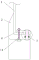
FIG. 1 is a schematic view of the overall left-side cross-sectional structure of the present invention;
FIG. 2 is an enlarged schematic view of the structure at A in FIG. 1 according to the present invention;
FIG. 3 is a schematic top view of the connecting groove between the metal plate and the fluted disc of the present invention;
FIG. 4 is a front view of the wheel arch body of the present invention;
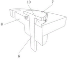
FIG. 5 is a schematic view of a three-dimensional cross-sectional structure of the wheel arch positioning rod and the fluted disc connecting groove of the present invention.
In the figure: 1. vehicle sheet metal; 2. a wheel arch body; 3. a spring mounting bin; 4. a pressure spring; 5. a limiting plate; 6. a wheel arch positioning rod; 7. aligning a fluted disc; 8. sheet metal connecting sheets; 9. a rotating shaft; 10. a fluted disc connecting groove; 11. and (5) fixing the bolt.
Detailed Description
The technical solutions in the embodiments of the present invention will be described clearly and completely with reference to the accompanying drawings in the embodiments of the present invention, and it is obvious that the described embodiments are only some embodiments of the present invention, not all embodiments. Based on the embodiments in the present invention, all other embodiments obtained by a person skilled in the art without creative work belong to the protection scope of the present invention.
Referring to fig. 1-5, the present invention provides a technical solution: a front wheel arch structure of an automobile convenient for positioning comprises a vehicle metal plate 1 and a fluted disc connecting groove 10, wherein the left side of the vehicle metal plate 1 is connected with a wheel arch body 2, a spring mounting bin 3 is arranged inside the right side of the wheel arch body 2, the top surface of the spring installation bin 3 is connected with one end of a pressure spring 4, the other end of the pressure spring 4 is connected with the top surface of a limiting plate 5, the limiting plate 5 is arranged on a wheel arch positioning rod 6, the top end of the wheel arch positioning rod 6 is provided with an alignment fluted disc 7, the bottom surface of the contraposition fluted disc 7 is connected with a fluted disc connecting groove 10, the fluted disc connecting groove 10 is arranged on the top surface of the sheet metal connecting sheet 8, the bottom of the sheet metal connecting sheet 8 is connected with a rotating shaft 9, the rotating shaft 9 is arranged on the top surface of the wheel arch body 2, the sheet metal connecting sheet 8 is connected with the top end of the fixing bolt 11, and meanwhile, the fixing bolt 11 penetrates through the sheet metal connecting sheet 8, the vehicle sheet metal 1 and the wheel arch body 2;
Limiting plate 5 symmetric distribution is in the both sides of wheel arch locating lever 6, and limiting plate 5 constitutes integrated structure with wheel arch locating lever 6, can carry out spacing work to limiting plate 5 through 3 effectually in spring mounting storehouse to stabilizing wheel arch locating lever 6, guaranteeing that wheel arch locating lever 6 can not produce the skew on the angle when counterpoint fluted disc 7 is connected with fluted disc spread groove 10.
Counterpoint fluted disc 7 is connected for the block with the connected mode of fluted disc spread groove 10, and the volume of counterpoint fluted disc 7 equals the volume of fluted disc spread groove 10, can guarantee through the laminating between counterpoint fluted disc 7 and the fluted disc spread groove 10 that sheet metal connection piece 8 has the pressure that lasts to vehicle panel beating 1, still is favorable to sheet metal connection piece 8's angle modulation simultaneously.
The connection mode of sheet metal connection piece 8 and rotation axis 9 is swivelling joint, and the centre of a circle that the rotatory axle center of sheet metal connection piece 8 and counterpoint fluted disc 7 place are on same straight line, can carry out the extrusion stability work to vehicle panel beating 1 through the rotation between sheet metal connection piece 8 and the rotation axis 9, the stability that simultaneously can further increase wheel arch and vehicle connection.
The cross sectional shape of sheet metal connection piece 8 is semiellipse, and sheet metal connection piece 8's length is greater than vehicle panel beating 1's bottom length, be favorable to carrying out the regulation to 8 angles of sheet metal connection piece according to the length of 1 bottom of vehicle panel beating, guaranteed that sheet metal connection piece 8 can be in the in-process of selecting groups can laminate with vehicle panel beating 1, thereby carry out the stable connection of wheel arch and panel beating, when the straight line face at sheet metal connection piece 8 is rotatory to being nearest apart from vehicle panel beating 1 simultaneously, can take off the wheel arch.
The working principle is as follows: according to the figures 1-5, when the wheel arch and the vehicle metal plate 1 are installed, the wheel arch body 2 can be attached to the vehicle metal plate 1, the wheel arch positioning rod 6 is pressed upwards, the limiting plate 5 on the wheel arch positioning rod 6 extrudes the pressure spring 4 in the spring installation bin 3, the alignment fluted disc 7 arranged at the top end of the wheel arch positioning rod 6 is separated from the fluted disc connecting groove 10, the sheet metal connecting piece 8 is unlocked, the sheet metal connecting piece 8 is rotated through the rotating shaft 9 until the sheet metal connecting piece 8 is connected with the vehicle metal plate 1, the wheel arch positioning rod 6 is loosened when the sheet metal connecting piece 8 is connected with the vehicle metal plate 1, the wheel arch positioning rod 6 resets the pressure of the limiting plate 5 through the pressure spring 4, the alignment fluted disc 7 is connected with the fluted disc connecting groove 10 to perform stable work on the position of the sheet metal connecting piece 8, and finally the fixing bolt 11 penetrates through the vehicle, The wheel arch body 2 and the sheet metal connecting sheet 8 are fixed in the last step, so that the wheel arch installation work is completed, which is the working process of the whole device, and the contents which are not described in detail in the specification belong to the prior art which is known by the professional technicians in the field.
Spatially relative terms, such as "above … …," "above … …," "above … …," "above," and the like, may be used herein for ease of description to describe one device or feature's spatial relationship to another device or feature as illustrated in the figures. It will be understood that the spatially relative terms are intended to encompass different orientations of the device in use or operation in addition to the orientation depicted in the figures. For example, if a device in the figures is turned over, devices described as "above" or "on" other devices or configurations would then be oriented "below" or "under" the other devices or configurations. Thus, the exemplary term "above … …" can include both an orientation of "above … …" and "below … …". The device may be otherwise variously oriented (rotated 90 degrees or at other orientations) and the spatially relative descriptors used herein interpreted accordingly.
Although embodiments of the present invention have been shown and described, it will be appreciated by those skilled in the art that changes, modifications, substitutions and alterations can be made in these embodiments without departing from the principles and spirit of the invention, the scope of which is defined in the appended claims and their equivalents.
Claims (6)
1. The utility model provides a wheel arch structure before car convenient to location, includes vehicle panel beating (1) and fluted disc spread groove (10), its characterized in that: the left side of the vehicle metal plate (1) is connected with the wheel arch body (2), the spring installation bin (3) is arranged inside the right side of the wheel arch body (2), the top surface of the spring installation bin (3) is connected with one end of the pressure spring (4), the other end of the pressure spring (4) is connected with the top surface of the limiting plate (5), the limiting plate (5) is arranged on the wheel arch positioning rod (6), the top end of the wheel arch positioning rod (6) is provided with an alignment fluted disc (7), the bottom surface of the alignment fluted disc (7) is connected with a fluted disc connecting groove (10), the fluted disc connecting groove (10) is arranged on the top surface of the metal plate connecting piece (8), the bottom of the metal plate connecting piece (8) is connected with the rotating shaft (9), the rotating shaft (9) is arranged on the top surface of the wheel arch body (2), and the metal plate connecting piece (8) is connected with the top end of the, meanwhile, the fixing bolt (11) penetrates through the sheet metal connecting piece (8) and the vehicle sheet metal (1) and the wheel arch body (2).
2. The automobile front wheel arch structure convenient to position as claimed in claim 1, wherein: spring mounting storehouse (3) and limiting plate (5) are fixed connection with the connected mode of pressure spring (4), and the width in spring mounting storehouse (3) equals the width of limiting plate (5) to limiting plate (5) symmetric distribution is in the both sides of wheel arch locating lever (6).
3. The automobile front wheel arch structure convenient to position as claimed in claim 1, wherein: limiting plates (5) are symmetrically distributed on two sides of the wheel arch positioning rod (6), and the limiting plates (5) and the wheel arch positioning rod (6) form an integrated structure.
4. The automobile front wheel arch structure convenient to position as claimed in claim 1, wherein: the counterpoint fluted disc (7) is connected with the fluted disc connecting groove (10) in a clamping manner, and the volume of the counterpoint fluted disc (7) is equal to that of the fluted disc connecting groove (10).
5. The automobile front wheel arch structure convenient to position as claimed in claim 1, wherein: the connection mode of the sheet metal connecting piece (8) and the rotating shaft (9) is rotary connection, and the rotating shaft center of the sheet metal connecting piece (8) and the circle center of the contraposition fluted disc (7) are on the same straight line.
6. The automobile front wheel arch structure convenient to position as claimed in claim 1, wherein: the cross section of the sheet metal connecting piece (8) is semi-elliptical, and the length of the sheet metal connecting piece (8) is greater than the length of the bottom of the vehicle sheet metal (1).
Priority Applications (1)
| Application Number | Priority Date | Filing Date | Title |
|---|---|---|---|
| CN202022576392.XU CN213534603U (en) | 2020-11-10 | 2020-11-10 | Automobile front wheel arch structure convenient to locate |
Applications Claiming Priority (1)
| Application Number | Priority Date | Filing Date | Title |
|---|---|---|---|
| CN202022576392.XU CN213534603U (en) | 2020-11-10 | 2020-11-10 | Automobile front wheel arch structure convenient to locate |
Publications (1)
| Publication Number | Publication Date |
|---|---|
| CN213534603U true CN213534603U (en) | 2021-06-25 |
Family
ID=76481264
Family Applications (1)
| Application Number | Title | Priority Date | Filing Date |
|---|---|---|---|
| CN202022576392.XU Expired - Fee Related CN213534603U (en) | 2020-11-10 | 2020-11-10 | Automobile front wheel arch structure convenient to locate |
Country Status (1)
| Country | Link |
|---|---|
| CN (1) | CN213534603U (en) |
-
2020
- 2020-11-10 CN CN202022576392.XU patent/CN213534603U/en not_active Expired - Fee Related
Similar Documents
| Publication | Publication Date | Title |
|---|---|---|
| EP3858716B1 (en) | Chassis of automatic guided vehicle and automatic guided vehicle | |
| JP6527309B2 (en) | Vehicle wheel structure | |
| CN106428170B (en) | A kind of wheel hub transport trolleys special car body | |
| CN206938649U (en) | A kind of integral type car roof decorative strip attachment structure | |
| CN102774234A (en) | Air supply wheel hub | |
| CN206254912U (en) | A kind of adjustable type prevents the flexible pedal for colliding with | |
| CN206031233U (en) | Vehicle mobile phone support of convenient use | |
| CN106944500A (en) | Bridge type auto depression fix tool | |
| CA2355770A1 (en) | Tire with rounded bead toe and a mold for forming the tire | |
| CN208411917U (en) | Clip wheel device | |
| CN207417035U (en) | Electromobile frame back vent and electric car | |
| CN201350940Y (en) | Folding joint of folding bicycle | |
| CN206122011U (en) | Car bumper vehicle -mounted body application mechanism | |
| CN205930935U (en) | Go up brake pedal assembly and car | |
| CN103556896A (en) | Eccentric shaft gooseneck type trunk hinge, trunk lid assembly and vehicle | |
| CN216516730U (en) | Beautiful seam construction equipment | |
| CN223821430U (en) | Standard bracket for connecting glass awning and sunshade curtain frame | |
| CN213828887U (en) | Automobile part machining device convenient for angle adjustment | |
| CN211901201U (en) | Assembled gum tool | |
| CN204137223U (en) | Three-wheel scooter | |
| CN103569075A (en) | Portable parking device on automobile | |
| CN206265139U (en) | A kind of vehicle frame for electric motor car | |
| CN214320649U (en) | Processing platform for producing solid wood door | |
| CN212601551U (en) | F-shaped wrench for thermal valve | |
| CN110466627A (en) | A kind of car trunk spare tire cover plate supporting block and support construction |
Legal Events
| Date | Code | Title | Description |
|---|---|---|---|
| GR01 | Patent grant | ||
| GR01 | Patent grant | ||
| CF01 | Termination of patent right due to non-payment of annual fee |
Granted publication date: 20210625 |
|
| CF01 | Termination of patent right due to non-payment of annual fee |