CN213909823U - Panel assembly and cooking utensil with same - Google Patents
Panel assembly and cooking utensil with same Download PDFInfo
- Publication number
- CN213909823U CN213909823U CN202022483121.XU CN202022483121U CN213909823U CN 213909823 U CN213909823 U CN 213909823U CN 202022483121 U CN202022483121 U CN 202022483121U CN 213909823 U CN213909823 U CN 213909823U
- Authority
- CN
- China
- Prior art keywords
- panel assembly
- base
- display screen
- wire passing
- cooking appliance
- Prior art date
- Legal status (The legal status is an assumption and is not a legal conclusion. Google has not performed a legal analysis and makes no representation as to the accuracy of the status listed.)
- Active
Links
Images


Landscapes
- Baking, Grill, Roasting (AREA)
Abstract
The utility model provides a panel components and have its cooking utensil, wherein, panel components, include: the fixed plate is provided with a first wire passing groove; the display screen is arranged on the fixing plate and comprises a screen body and a flat cable connected with the screen body; the drive plate is located one side of fixed plate far away from the display screen, is provided with binding post and second on the drive plate and crosses the wire casing, and binding post is located one side that the display screen was kept away from to the drive plate, and the second crosses the wire casing and corresponds the setting with first line casing, and the winding displacement passes first line casing and second and crosses the wire casing and with binding post cooperation. The technical scheme of the application has effectively solved the problem that the winding displacement among the correlation technique damaged.
Description
RELATED APPLICATIONS
The priority of the chinese patent application having application number 202021801591.X entitled "panel assembly and cooking appliance having the same", filed on 25/8/2020, is hereby incorporated by reference in its entirety.
Technical Field
The utility model relates to a small household appliances technical field particularly, relates to a panel components and have its cooking utensil.
Background
The cooking appliance generally displays an operation mode of the cooking appliance and an operation function of a user through a display device. The display device of the cooking utensil is positioned on the outer side of the panel, the driving board of the cooking utensil is installed on the inner side of the panel, and the display device is connected with the driving board through a flat cable.
In the wiring process of the flat cable, the flat cable is wound around the outer side of the driving plate, so that the winding is too far, multiple folding is generated, and the flat cable is damaged.
SUMMERY OF THE UTILITY MODEL
The utility model discloses a main aim at provides a panel components and have its cooking utensil to solve the problem that the winding displacement among the correlation technique damaged.
In order to achieve the above object, according to an aspect of the present invention, there is provided a panel assembly including: the fixed plate is provided with a first wire passing groove; the display screen is arranged on the fixing plate and comprises a screen body and a flat cable connected with the screen body; the drive plate is located one side of fixed plate far away from the display screen, is provided with binding post and second on the drive plate and crosses the wire casing, and binding post is located one side that the display screen was kept away from to the drive plate, and the second crosses the wire casing and corresponds the setting with first line casing, and the winding displacement passes first line casing and second and crosses the wire casing and with binding post cooperation.
Use the technical scheme of the utility model, winding displacement on the display screen passes the first wire casing of crossing on the fixed plate, passes the second wire casing of crossing on the drive plate again, and the winding displacement can be pegged graft with binding post and cooperate. Therefore, the display screen is electrically connected with the driving board to realize electrification. In the process of arranging the flat cable, the second wire passing groove and the first wire passing groove are correspondingly arranged, the flat cable does not need to bypass the driving plate to perform too far wire winding, multiple folding is avoided, and the possibility of damage of the flat cable is reduced. Therefore, the technical scheme of the application effectively solves the problem of damage of the flat cable in the related art.
Furthermore, in order to prevent the flat cable and components on the driving plate from being damaged due to high temperature, the panel assembly further comprises a heat insulation cover covering the outer side of the driving plate, and the heat insulation cover is connected with the fixing plate. The flat cable and all the driving plates are covered by the heat insulation cover, so that higher temperature can be isolated.
Further, in order to reliably connect the heat shield to the fastening plate, the heat shield is connected to the fastening plate by snapping and/or screwing.
Further, in order to enable the flat cable to smoothly pass through the second wire passing groove and the first wire passing groove, the second wire passing groove and/or the first wire passing groove are in clearance fit with the flat cable.
Furthermore, the fixing plate is provided with a containing cavity for containing the display screen, and the first wire passing groove is formed in the wall of the containing cavity. The display screen does not protrude out of the upper surface of the fixing plate, so that the appearance of the panel assembly is smooth.
According to another aspect of the present invention, there is provided a cooking appliance, comprising a panel assembly, the panel assembly being the above panel assembly. Since the panel assembly described above can solve the problem of damage of the flat cable in the related art, the cooking appliance including the panel assembly has the same effect.
Further, the cooking appliance further includes: the panel assembly is arranged on the base; a container mounted on the base; the heat preservation cover is arranged in the base. Because the heat-insulating cover is positioned in the base, the heat-insulating cover is not exposed out of the base, a user cannot directly contact the heat-insulating cover, and the problem that the user is easily scalded by the heat-insulating cover is avoided.
Further, to facilitate the user's manipulation of the panel assembly, the front of the base is lower than the rear of the base, and the panel assembly is located at the front of the base.
Further, in order to minimize the influence of heat generated from the heating device on the terminal of the panel assembly, the terminal of the panel assembly is located at a rim of the driving plate of the panel assembly away from the container.
According to another aspect of the present invention, there is provided a cooking appliance, including a panel assembly, the panel assembly being the above panel assembly, the cooking appliance further including: the panel assembly is arranged on the base; the container is installed in the base, wherein, is provided with the outlet on the side of keeping away from the container of panel components's heat exchanger, and the wire of drive plate is worn out from the outlet. The outlet is located on the side of the heat shield remote from the vessel so that the wires of the drive plate are less affected by the heat generated by the heating means.
Drawings
The accompanying drawings, which form a part of the present application, are included to provide a further understanding of the invention, and are incorporated in and constitute a part of this specification, illustrate embodiments of the invention and together with the description serve to explain the invention and not to limit the invention. In the drawings:
fig. 1 shows a schematic top view of a panel assembly of an embodiment of a cooking appliance according to the present invention mounted on a base;
FIG. 2 shows a schematic sectional view of the cooking appliance of FIG. 1 from A-A; and
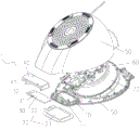
fig. 3 illustrates an exploded view of a panel assembly of the cooking appliance of fig. 1.
Wherein the figures include the following reference numerals:
1. a panel assembly; 10. a fixing plate; 11. a first wire passing groove; 12. an accommodating chamber; 20. a display screen; 21. a screen body; 22. arranging wires; 30. a drive plate; 31. a wiring terminal; 32. a second wire passing groove; 40. a heat shield; 41. an outlet; 50. a base; 60. a heating device; 70. and (4) a heat preservation cover.
Detailed Description
The technical solutions in the embodiments of the present invention will be described clearly and completely with reference to the accompanying drawings in the embodiments of the present invention, and it is obvious that the described embodiments are only some embodiments of the present invention, not all embodiments. The following description of at least one exemplary embodiment is merely illustrative in nature and is in no way intended to limit the invention, its application, or uses. Based on the embodiments in the present invention, all other embodiments obtained by a person skilled in the art without creative efforts belong to the protection scope of the present invention.
It is noted that the terminology used herein is for the purpose of describing particular embodiments only and is not intended to be limiting of example embodiments according to the present application. As used herein, the singular forms "a", "an" and "the" are intended to include the plural forms as well, and it should be understood that when the terms "comprises" and/or "comprising" are used in this specification, they specify the presence of stated features, steps, operations, devices, components, and/or combinations thereof, unless the context clearly indicates otherwise.
Unless specifically stated otherwise, the relative arrangement of the components and steps, the numerical expressions, and numerical values set forth in these embodiments do not limit the scope of the present invention. Meanwhile, it should be understood that the sizes of the respective portions shown in the drawings are not drawn in an actual proportional relationship for the convenience of description. Techniques, methods, and apparatus known to those of ordinary skill in the relevant art may not be discussed in detail but are intended to be part of the specification where appropriate. In all examples shown and discussed herein, any particular value should be construed as merely illustrative, and not limiting. Thus, other examples of the exemplary embodiments may have different values. It should be noted that: like reference numbers and letters refer to like items in the following figures, and thus, once an item is defined in one figure, further discussion thereof is not required in subsequent figures.
As shown in fig. 2 and 3, the panel assembly of the present embodiment includes: a fixed plate 10, a display screen 20 and a driving board 30. The fixing plate 10 is provided with a first wire passing groove 11. The display screen 20 is mounted on the fixing plate 10, and the display screen 20 includes a screen body 21 and a flat cable 22 connected to the screen body 21. The driving board 30 is located on one side of the fixing board 10 far away from the display screen 20, and the connecting terminal 31 and the second wire passing groove 32 are arranged on the driving board 30. The connection terminal 31 is located on a side of the driving board 30 away from the display screen 20. The second wire passing groove 32 is arranged corresponding to the first wire passing groove 11. The flat cable 22 passes through the first and second wire passing grooves 11 and 32 and is engaged with the terminal block 31.
By applying the technical scheme of the embodiment, the flat cable 22 on the display screen 20 passes through the first wire passing groove 11 on the fixing plate 10 and then passes through the second wire passing groove 32 on the driving plate 30, and the flat cable 22 and the wiring terminal 31 can be matched in an inserted manner. In this way, the display panel 20 is electrically connected to the driving board 30, and thus, the power is supplied. In the process of arranging the flat cables, the second wire passing grooves 32 are arranged corresponding to the first wire passing grooves 11, the flat cables do not need to be wound far around the driving plate 30, multiple folding is avoided, and the possibility of damaging the flat cables is reduced. Therefore, the technical scheme of the embodiment effectively solves the problem of damage of the flat cable in the related art. In addition, the flat cable 22 directly passes through the first and second wire passing grooves 11 and 32 and is matched with the wiring terminal 31, so that the assembly process of the panel assembly is simplified.
The display 20, the fixing plate 10, and the driving plate 30 may be sequentially disposed in the vertical direction of the cooking appliance, or may be sequentially disposed in the front-rear direction of the user in the cooking appliance.
As shown in fig. 3, in order to prevent the flat cable 22 and the components on the driving plate 30 from being damaged due to a high temperature, the panel assembly further includes a heat shield 40 covering the outside of the driving plate 30, and the heat shield 40 is connected to the fixing plate 10. In this way, the heat shield 40 shields the flex cable 22 and all of the drive plate 30 from the higher temperatures.
As shown in fig. 2 and 3, the heat shield 40 is connected to the fixing plate 10 by snap-fitting so that the heat shield 40 can be reliably connected to the fixing plate 10.
Of course, in other embodiments not shown in the figures, the heat shield is connected to the fixing plate by snapping and screwing, or the heat shield is connected to the fixing plate only by screwing.
As shown in fig. 2, in order to enable the flat cable 22 to smoothly pass through the second wire passage groove 32 and the first wire passage groove 11, both the second wire passage groove 32 and the first wire passage groove 11 are in clearance fit with the flat cable 22.
Of course, in other embodiments not shown in the figures, the second wire passing groove or the first wire passing groove is in clearance fit with the flat cable.
As shown in fig. 2, in order to enable the display screen 20 to be flatly fixed on the fixing plate 10, an accommodating chamber 12 for accommodating the display screen 20 is provided on the fixing plate 10, and the first wire passing groove 11 is provided on a wall of the accommodating chamber 12. Thus, the display screen 20 is not protruded from the upper surface of the fixing plate 10, so that the appearance of the panel assembly is flat.
The present application further provides a cooking appliance, as shown in fig. 1 to 3, the cooking appliance of the present embodiment includes a panel assembly 1, and the panel assembly is the above-mentioned panel assembly. Since the panel assembly described above can solve the problem of damage of the flat cable in the related art, the cooking appliance including the panel assembly has the same effect.
As shown in fig. 2 and 3, the cooking appliance further includes: a base 50, a container (not shown) and a heat retaining cover 70. The panel assembly 1 is disposed on the base 50. The container is mounted to a base 50. The heat-retaining cover 70 is installed inside the base 50. Because the heat preservation cover 70 is located inside the base 50, the heat preservation cover 70 is not exposed out of the base 50, and a user cannot directly contact the heat preservation cover 70, so that the problem that the user is easily scalded by the heat preservation cover is solved. In this embodiment, the cooking appliance further comprises a heating device 60 located within the heat retaining cover 70, and the heating device 60 is located at the bottom of the container. The heating device 60 of the present embodiment is preferably an electric hot plate.
As shown in fig. 1, in order to facilitate the user's manipulation of the panel assembly, the front of the base 50 is lower than the rear of the base 50, and the panel assembly 1 is located at the front of the base 50. The front portion refers to the direction towards the user, i.e. the side where the display screen is located, while the rear portion is the side corresponding to the front portion.
As shown in fig. 1 and 3, in order to minimize the influence of heat generated from the heating device 60 on the connection terminal 31 of the panel assembly 1, the connection terminal 31 of the panel assembly 1 is located at the edge of the driving plate 30 of the panel assembly 1 away from the container.
The present application also provides a cooking appliance, as shown in fig. 1 and 3, the cooking appliance of the present embodiment includes a panel assembly 1, which is the above-mentioned panel assembly. Since the panel assembly described above can solve the problem of damage of the flat cable in the related art, the cooking appliance including the panel assembly has the same effect. The cooking appliance further includes: a base 50 and a container. The panel assembly 1 is disposed on the base 50. The container is mounted to a base 50. Wherein, the side of the heat shield 40 of the panel assembly 1 far away from the container is provided with an outlet 41, and the lead wire of the driving plate 30 passes through the outlet 41. The outlet 41 is located on the side of the heat shield 40 remote from the vessel so that the wires of the drive plate 30 are less affected by the heat generated by the heating means 60.
The cooking appliance of the present embodiment is an electric pressure cooker. Of course, in the embodiment not shown in the figures, the cooking appliance can also be an electric cooker, a low-pressure rice cooker, a soybean milk maker, a food processor, an electric stewpan, a cooking machine, a multifunctional pot and the like.
In the description of the present invention, it should be understood that the orientation or positional relationship indicated by the orientation words such as "front, back, up, down, left, right", "horizontal, vertical, horizontal" and "top, bottom" etc. are usually based on the orientation or positional relationship shown in the drawings, and are only for convenience of description and simplification of description, and in the case of not making a contrary explanation, these orientation words do not indicate and imply that the device or element referred to must have a specific orientation or be constructed and operated in a specific orientation, and therefore, should not be interpreted as limiting the scope of the present invention; the terms "inner and outer" refer to the inner and outer relative to the profile of the respective component itself.
Spatially relative terms, such as "above … …," "above … …," "above … …," "above," and the like, may be used herein for ease of description to describe one device or feature's spatial relationship to another device or feature as illustrated in the figures. It will be understood that the spatially relative terms are intended to encompass different orientations of the device in use or operation in addition to the orientation depicted in the figures. For example, if a device in the figures is turned over, devices described as "above" or "on" other devices or configurations would then be oriented "below" or "under" the other devices or configurations. Thus, the exemplary term "above … …" can include both an orientation of "above … …" and "below … …". The device may be otherwise variously oriented (rotated 90 degrees or at other orientations) and the spatially relative descriptors used herein interpreted accordingly.
It should be noted that the terms "first", "second", and the like are used to define the components, and are only used for convenience of distinguishing the corresponding components, and if not stated otherwise, the terms have no special meaning, and therefore, the scope of the present invention should not be construed as being limited.
The above description is only a preferred embodiment of the present invention and is not intended to limit the present invention, and various modifications and changes may be made by those skilled in the art. Any modification, equivalent replacement, or improvement made within the spirit and principle of the present invention should be included in the protection scope of the present invention.
Claims (10)
1. A panel assembly, comprising:
the fixing plate (10) is provided with a first wire passing groove (11);
the display screen (20) is installed on the fixing plate (10), and the display screen (20) comprises a screen body (21) and a flat cable (22) connected with the screen body (21);
the driving plate (30) is located keeping away from the fixing plate (10) on one side of the display screen (20), a wiring terminal (31) and a second wire passing groove (32) are arranged on the driving plate (30), the wiring terminal (31) is located on one side of the display screen (20) far away from the driving plate (30), the second wire passing groove (32) corresponds to the first wire passing groove (11), and the flat cable (22) penetrates through the first wire passing groove (11) and the second wire passing groove (32) and is matched with the wiring terminal (31).
2. The panel assembly according to claim 1, further comprising a heat shield (40) covering an outer side of the driving plate (30), the heat shield (40) being connected to the fixing plate (10).
3. The panel assembly according to claim 2, wherein the heat shield (40) is connected to the fixing plate (10) by snapping and/or screwing.
4. A panel assembly according to any one of claims 1 to 3, characterised in that the second wire guide channel (32) and/or the first wire guide channel (11) is a clearance fit with the flex cable (22).
5. The panel assembly according to any one of claims 1 to 3, wherein a receiving cavity (12) for receiving the display screen (20) is provided on the fixing plate (10), and the first wire passing groove (11) is provided on a cavity wall of the receiving cavity (12).
6. Cooking appliance comprising a panel assembly (1), characterized in that it is a panel assembly according to any one of claims 1 to 5.
7. The cooking appliance of claim 6, further comprising:
a base (50), the panel assembly (1) being disposed on the base (50);
a container mounted to the base (50);
and the heat preservation cover (70) is arranged in the base (50).
8. The cooking appliance according to claim 7, wherein the front of the base (50) is lower than the rear of the base (50), the panel assembly (1) being located at the front of the base (50).
9. The cooking appliance according to claim 7, wherein the connection terminal (31) of the panel assembly (1) is located at a rim of the drive plate (30) of the panel assembly (1) remote from the container.
10. A cooking appliance comprising a panel assembly (1), characterized in that it is a panel assembly according to claim 2, the cooking appliance further comprising:
a base (50), the panel assembly (1) being disposed on the base (50);
the container is mounted on the base (50), wherein an outlet (41) is formed in the side face, far away from the container, of the heat insulation cover (40) of the panel assembly (1), and the lead of the driving plate (30) penetrates out of the outlet (41).
Applications Claiming Priority (2)
| Application Number | Priority Date | Filing Date | Title |
|---|---|---|---|
| CN202021801591X | 2020-08-25 | ||
| CN202021801591 | 2020-08-25 |
Publications (1)
| Publication Number | Publication Date |
|---|---|
| CN213909823U true CN213909823U (en) | 2021-08-10 |
Family
ID=77164845
Family Applications (2)
| Application Number | Title | Priority Date | Filing Date |
|---|---|---|---|
| CN202022483121.XU Active CN213909823U (en) | 2020-08-25 | 2020-10-30 | Panel assembly and cooking utensil with same |
| CN202022477808.2U Active CN213909822U (en) | 2020-08-25 | 2020-10-30 | Cooking utensil |
Family Applications After (1)
| Application Number | Title | Priority Date | Filing Date |
|---|---|---|---|
| CN202022477808.2U Active CN213909822U (en) | 2020-08-25 | 2020-10-30 | Cooking utensil |
Country Status (1)
| Country | Link |
|---|---|
| CN (2) | CN213909823U (en) |
-
2020
- 2020-10-30 CN CN202022483121.XU patent/CN213909823U/en active Active
- 2020-10-30 CN CN202022477808.2U patent/CN213909822U/en active Active
Also Published As
| Publication number | Publication date |
|---|---|
| CN213909822U (en) | 2021-08-10 |
Similar Documents
| Publication | Publication Date | Title |
|---|---|---|
| EP3711636A1 (en) | Electric kettle | |
| CN214804068U (en) | Cooking utensil | |
| JPH0668967A (en) | Incorporated type heating cooker | |
| CN210124596U (en) | Cooking utensil | |
| CN218484315U (en) | Cooking utensil | |
| CN213909822U (en) | Cooking utensil | |
| CN216797309U (en) | Cooking utensil | |
| CN211632761U (en) | Voice device and cooking utensil | |
| CN215735249U (en) | Accommodating assembly and household appliance | |
| CN205860126U (en) | Electromagnetic oven, electromagnetism electric cooking appliance body and electromagnetic rice cooker | |
| CN210008872U (en) | Cooking utensil | |
| CN212912756U (en) | Cooking utensil | |
| CN219895343U (en) | Pot body and cooking utensil | |
| CN213551274U (en) | Pot body subassembly and have its cooking utensil | |
| CN214595449U (en) | Lid assembly and have its cooking utensil | |
| CN209966112U (en) | Cooking utensil | |
| CN217659314U (en) | Accommodating assembly and household appliance | |
| CN208973328U (en) | Cooking apparatus | |
| CN219795085U (en) | Door plate with intelligent handle and oven with door plate | |
| CN215016112U (en) | Cooking utensil | |
| CN220212620U (en) | Pot body and cooking utensil with same | |
| CN212912753U (en) | Base subassembly and have its cooking utensil | |
| CN105953272B (en) | A kind of micro-wave oven of band APP module | |
| CN210121064U (en) | Temperature sensing assembly and cooking utensil with same | |
| CN216962186U (en) | Handle assembly and frying and baking machine |
Legal Events
| Date | Code | Title | Description |
|---|---|---|---|
| GR01 | Patent grant | ||
| GR01 | Patent grant |