CN213913248U - Organic fertilizer agitating unit - Google Patents
Organic fertilizer agitating unit Download PDFInfo
- Publication number
- CN213913248U CN213913248U CN202022819075.6U CN202022819075U CN213913248U CN 213913248 U CN213913248 U CN 213913248U CN 202022819075 U CN202022819075 U CN 202022819075U CN 213913248 U CN213913248 U CN 213913248U
- Authority
- CN
- China
- Prior art keywords
- wall
- stirring
- tank body
- shaft
- organic fertilizer
- Prior art date
- Legal status (The legal status is an assumption and is not a legal conclusion. Google has not performed a legal analysis and makes no representation as to the accuracy of the status listed.)
- Active
Links
Images


Landscapes
- Mixers Of The Rotary Stirring Type (AREA)
Abstract
An organic fertilizer stirring device comprises a tank body, wherein a feed hopper is arranged at the top of one end of the tank body, a discharge port is formed at the bottom of the tank body, the two ends of the discharge port are flush with the end wall of the tank body, a cover body is matched with the discharge port, the inner wall of the cover body is in an arc shape which is superposed with the inner wall of the tank body, and the cover body can rotate along one long edge of the cover body; the stirring mechanism comprises a stirring shaft, the two ends of the stirring shaft are rotatably connected with the end wall of the tank body, a plurality of groups of stirring rods are arranged on the periphery of the stirring shaft along the length direction of the stirring shaft, the end parts of the stirring rods are connected with stirring blades, the outer walls of the stirring blades are arc-shaped and are attached to the inner wall of the tank body, the inner walls of the stirring blades are inclined towards the other side of the outer wall of the stirring blades from one side of the inner wall of the stirring blades, one side of each stirring blade is provided with a baffle, and the rotating tracks of adjacent groups of stirring blades are overlapped. The stirring leaf outer wall is the arc with the laminating of jar internal wall, and the rotation orbit coincidence of adjacent group stirring leaf, can strike off the material attached at jar internal wall, because in discharge gate both ends and jar body end wall parallel and level, guarantees that the material is whole to be discharged through the discharge gate.
Description
Technical Field
The utility model relates to an organic fertilizer production facility field is relevant with an organic fertilizer agitating unit very much.
Background
The organic fertilizer is made up by using green manure, oil cake, ligusticum root and dung and urine through a certain preparation process, and contains lots of organic substances and several nutrient elements, and its source is extensive, preparation is convenient, fertilizer efficiency is durable, and it can produce humus, improve soil and increase yield of crops. When the organic fertilizer is produced, the materials are required to be stirred, so that the components are uniformly distributed, and the overall quality of the product is improved. Present raw materials mix the stirring and adopt the mixer more, because stirring leaf simple structure is difficult to realize stirring fully to the material, leads to the material mixing uniformity relatively poor, simultaneously, for the leakproofness when guaranteeing the material stirring, an export is generally only seted up in the bottom of agitator tank, influences the discharge of material, needs the manual work to wash, and work efficiency is low.
SUMMERY OF THE UTILITY MODEL
To the problem that relevant prior art exists, the utility model provides an organic fertilizer agitating unit, stirring leaf outer wall be with the arc of a jar internal wall laminating, and the rotation orbit coincidence of adjacent group stirring leaf, can strike off attached material at a jar internal wall, reduce the clean process in later stage, prevent equipment corrosion, play certain guard action to equipment, because discharge gate both ends and jar body end wall parallel and level, guarantee that the material is whole to be discharged through the discharge gate.
In order to achieve the above purpose, the utility model adopts the following technology:
an organic fertilizer stirring device, comprising:
the tank body is in a horizontally arranged cylindrical shape, a feed hopper is arranged at the top of one end of the tank body, a discharge port is formed in the bottom of the tank body, two ends of the discharge port are flush with the end wall of the tank body, a cover body is matched with the discharge port, the inner wall of the cover body is in an arc shape superposed with the inner wall of the tank body, and the cover body can rotate along one long edge of the cover body;
the stirring mechanism is arranged in the tank body and comprises a stirring shaft, the two ends of the stirring shaft are rotatably connected with the end wall of the tank body, a plurality of groups of stirring rods are arranged on the periphery of the stirring shaft along the length direction of the stirring shaft, the end parts of the stirring rods are connected with stirring blades, the outer walls of the stirring blades are arc-shaped and attached to the inner wall of the tank body, the inner walls of the stirring blades are inclined towards the other side of the outer wall of the stirring blades from one side of the inner wall of the stirring blades, one side of each stirring blade is provided with a baffle, and the rotating tracks of adjacent groups of stirring blades are overlapped.
Furthermore, a window is arranged on the side wall of the tank body.
Furthermore, rotating shafts are arranged at two ends of the cover body and are rotatably connected with the end wall of the tank body, one of the rotating shafts is connected with a discharging motor, and the discharging motor is fixed on the tank body.
Further, jar body bottom is equipped with a plurality of bracing pieces, and the bracing piece bottom is connected with the block rubber.
Furthermore, one end of the stirring shaft is connected with a belt pulley, and the belt pulley is connected with a driving motor through a belt.
The utility model discloses beneficial effect:
1. the stirring leaf outer wall is the arc with the laminating of jar internal wall, and the rotation orbit coincidence of adjacent group stirring leaf, can strike off attached material at jar internal wall, reduces the clean process in later stage, prevents equipment corrosion, plays certain guard action to equipment, because discharge gate both ends and jar body end wall parallel and level, guarantees that the material is whole to be discharged through the discharge gate.
2. The material passes through the feeder hopper and adds jar internally, it removes to drive the stirring leaf through the puddler during the (mixing) shaft is rotatory, the baffle promotes the material and removes, the effect of stirring is improved, the lid inner wall is the arc with jar internal wall coincidence, it is obstructed when preventing to stir the leaf and rotating, rotatory lid behind the abundant mixing of material, make the finished product discharge by the discharge gate, can examine the running state of jar internal part spare part through the window, be convenient for maintain and maintain, shorten the equipment repair time, improve work efficiency.
3. The motor of unloading is rotatory through pivot control lid, realizes the switching of discharge gate, and convenient operation prevents that stirring in-process material from leaking from the discharge gate, improves the leakproofness.
4. The bottom of the tank body is provided with a support through the support rod, and the bottom end of the support rod is connected with the rubber block, so that on one hand, the vibration received by the tank body can be buffered, the equipment abrasion is reduced, the service life is prolonged, on the other hand, the rubber block has a certain anti-skidding effect, the tank body is prevented from moving in the stirring process, and safety accidents occur.
Drawings
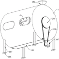
Fig. 1 is a schematic structural diagram of the present invention.
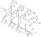
Fig. 2 is the structural schematic diagram of the stirring mechanism of the present invention.
Fig. 3 is a schematic view of the tank structure of the present invention.
Fig. 4 is a schematic view of a portion a of fig. 2.
Detailed Description
To make the objects, technical solutions and advantages of the embodiments of the present invention clearer, the following detailed description of the embodiments of the present invention is provided with reference to the accompanying drawings, but the described embodiments of the present invention are some embodiments of the present invention, not all embodiments.
It should be noted that: like reference numbers and letters refer to like items in the following figures, and thus, once an item is defined in one figure, it need not be further defined and explained in subsequent figures.
In the description of the present invention, it should be noted that the terms "center", "upper", "lower", "left", "right", "vertical", "horizontal", "inner", "outer", and the like indicate the position or positional relationship based on the position or positional relationship shown in the drawings, or the position or positional relationship that the product of the present invention is usually placed when in use, and this is only for the convenience of description of the present invention and simplification of the description. The terms "first," "second," and the like are used solely to distinguish one from another and are not to be construed as indicating or implying relative importance. The terms "parallel", "perpendicular", etc. do not require that the components be absolutely parallel or perpendicular, but may be slightly inclined.
In the description of the present invention, it should also be noted that, unless otherwise explicitly specified or limited, the terms "disposed," "mounted," "connected," and "connected" are to be construed broadly, and may be, for example, fixedly connected, detachably connected, or integrally connected; either directly or indirectly through intervening media, or through both elements. The specific meaning of the above terms in the present invention can be understood according to specific situations by those skilled in the art.
As shown in figures 1 to 3, the organic fertilizer stirring device comprises a cylindrical tank body 1 which is horizontally arranged and a stirring mechanism 2 which is arranged in the tank body 1.
The top of 1 one end of the jar body is equipped with feeder hopper 101, and discharge gate 102 has been seted up to 1 bottom of the jar body, and discharge gate 102 both ends and 1 end wall parallel and level of the jar body, and discharge gate 102 cooperation has lid 103, and the lid 103 inner wall is the arc with 1 inner wall coincidence of the jar body, and lid 103 can be followed a long limit rotation of lid 103, and window 104 has been seted up to 1 lateral wall of the jar body.
The stirring mechanism 2 comprises a stirring shaft 201, the two ends of the stirring shaft 201 are rotatably connected with the end wall of the tank body 1, the periphery of the stirring shaft 201 is provided with a plurality of groups of stirring rods 202 along the length direction of the stirring shaft 201, the end part of each stirring rod 202 is connected with a stirring blade 203, the outer wall of each stirring blade 203 is arc-shaped and is attached to the inner wall of the tank body 1, the inner wall of each stirring blade 203 is inclined towards the other side of the outer wall of each stirring blade 203 from one side of the inner wall of each stirring blade 203, one side of each stirring blade 203 is provided with a baffle 204, and the rotation tracks of the adjacent groups of stirring blades 203 are overlapped.
During stirring, various materials are added into the tank body 1 through the feed hopper 101, the stirring shaft 201 drives the stirring blades 203 to move through the stirring rod 202 when rotating, the baffle 204 pushes the materials to move, the stirring effect is improved, the outer walls of the stirring blades 203 are arc-shaped and are attached to the inner wall of the tank body 1, the rotating tracks of the adjacent groups of stirring blades 203 are overlapped, the materials attached to the inner wall of the tank body 1 can be scraped, the later cleaning process is reduced, the equipment corrosion is prevented, a certain protection effect is achieved on the equipment, the inner wall of the cover body 103 is arc-shaped and is overlapped with the inner wall of the tank body 1, the stirring blades 203 are prevented from being blocked when rotating, the cover body 103 is rotated after the materials are fully mixed, the finished products are discharged from the discharge port 102, because the two ends of the discharge port 102 are flush with the end wall of the tank body 1, the materials are all discharged through the discharge port 102, the running state of parts in the tank body 1 can be checked through a window, the maintenance and the maintenance are convenient, and the equipment overhaul time is shortened, the working efficiency is improved.
Further, as shown in fig. 4, two ends of the cover 103 are provided with rotating shafts 105, the rotating shafts 105 are rotatably connected to the end walls of the tank 1, one of the rotating shafts 105 is connected to a discharging motor 106, and the discharging motor 106 is fixed to the tank 1.
The discharging motor 106 controls the cover body 103 to rotate through the rotating shaft 105, so that the opening and closing of the discharging port 102 are realized, the operation is convenient, the leakage of materials from the discharging port 102 in the stirring process is prevented, and the sealing performance is improved.
Further, a plurality of support rods 107 are arranged at the bottom of the tank body 1, and the bottom ends of the support rods 107 are connected with rubber blocks 108.
The support is provided through bracing piece 107 in jar body 1 bottom, and bracing piece 107 bottom is connected with block rubber 108, can cushion the vibrations that jar body 1 received on the one hand, reduces equipment wear, increase of service life, and on the other hand block rubber 108 has certain anti-skidding effect, prevents that stirring in-process jar body 1 from removing, takes place the incident.
Further, one end of the stirring shaft 201 is connected with a pulley 205, and the pulley 205 is connected with a driving motor 207 through a belt 206.
The driving motor 207 controls the belt pulley 205 to rotate through the belt 206, so that the rotating speed of the stirring shaft 201 is adjusted, the material stirring requirement is met, and the stirring efficiency is improved.
The above description is only a preferred embodiment of the present invention and is not intended to limit the present invention, and it is obvious that those skilled in the art can make various changes and modifications to the present invention without departing from the spirit and scope of the present invention. Thus, if such modifications and variations of the present invention fall within the scope of the claims and their equivalents, the present invention is also intended to include such modifications and variations.
Claims (5)
1. An organic fertilizer agitating unit, its characterized in that includes:
the tank body (1) is in a horizontally arranged cylindrical shape, a feed hopper (101) is arranged at the top of one end of the tank body (1), a discharge port (102) is formed in the bottom of the tank body (1), the two ends of the discharge port (102) are flush with the end wall of the tank body (1), a cover body (103) is matched with the discharge port (102), the inner wall of the cover body (103) is in an arc shape which is superposed with the inner wall of the tank body (1), and the cover body (103) can rotate along one long edge of the cover body (103);
rabbling mechanism (2), locate jar internal (1), including (mixing) shaft (201), the (mixing) shaft (201) both ends are rotated and are connected jar body (1) end wall, the (mixing) shaft (201) periphery is equipped with multiunit puddler (202) along (mixing) shaft (201) length direction, puddler (202) end connection has stirring leaf (203), stirring leaf (203) outer wall is the arc with jar body (1) inner wall laminating, the inner wall of stirring leaf (203) is by stirring leaf (203) inner wall one side to stirring leaf (203) outer wall opposite side slope, stirring leaf (203) one side is equipped with baffle (204), the rotation orbit coincidence of adjacent group stirring leaf (203).
2. The organic fertilizer stirring device of claim 1, characterized in that: the side wall of the tank body (1) is provided with a window (104).
3. The organic fertilizer stirring device of claim 1, characterized in that: two ends of the cover body (103) are provided with rotating shafts (105), the rotating shafts (105) are rotatably connected with the end wall of the tank body (1), one rotating shaft (105) is connected with a discharging motor (106), and the discharging motor (106) is fixed on the tank body (1).
4. The organic fertilizer stirring device of claim 1, characterized in that: a plurality of supporting rods (107) are arranged at the bottom of the tank body (1), and the bottom ends of the supporting rods (107) are connected with rubber blocks (108).
5. The organic fertilizer stirring device of claim 1, characterized in that: one end of the stirring shaft (201) is connected with a belt pulley (205), and the belt pulley (205) is connected with a driving motor (207) through a belt (206).
Priority Applications (1)
| Application Number | Priority Date | Filing Date | Title |
|---|---|---|---|
| CN202022819075.6U CN213913248U (en) | 2020-11-30 | 2020-11-30 | Organic fertilizer agitating unit |
Applications Claiming Priority (1)
| Application Number | Priority Date | Filing Date | Title |
|---|---|---|---|
| CN202022819075.6U CN213913248U (en) | 2020-11-30 | 2020-11-30 | Organic fertilizer agitating unit |
Publications (1)
| Publication Number | Publication Date |
|---|---|
| CN213913248U true CN213913248U (en) | 2021-08-10 |
Family
ID=77146042
Family Applications (1)
| Application Number | Title | Priority Date | Filing Date |
|---|---|---|---|
| CN202022819075.6U Active CN213913248U (en) | 2020-11-30 | 2020-11-30 | Organic fertilizer agitating unit |
Country Status (1)
| Country | Link |
|---|---|
| CN (1) | CN213913248U (en) |
-
2020
- 2020-11-30 CN CN202022819075.6U patent/CN213913248U/en active Active
Similar Documents
| Publication | Publication Date | Title |
|---|---|---|
| CN107760555A (en) | A kind of biological fermentation tank for being easy to cleaning | |
| CN219051160U (en) | Mixer of variable speed stirring | |
| CN213913248U (en) | Organic fertilizer agitating unit | |
| CN213533174U (en) | Horizontal mixer is used in production of environmental protection concrete | |
| CN221432681U (en) | Edible fungus culture medium mixing device | |
| CN221999558U (en) | Fertilizer mixing equipment | |
| CN220737914U (en) | Raw material throwing device for fertilizer production | |
| CN219650304U (en) | Improved PVC mixer | |
| CN219599967U (en) | Concrete stirring device | |
| CN220241903U (en) | Horizontal concrete mixer | |
| CN221580476U (en) | Stirring device for processing natural diatomite putty | |
| CN223366712U (en) | Organic fertilizer raw material mixer | |
| CN221045957U (en) | Crushing and mixing integrated device for desulfurizing agent production | |
| CN224167342U (en) | Mixing arrangement is used in processing of rose fertilizer | |
| CN220466667U (en) | Vibration type feeding machine convenient for mixing | |
| CN220864314U (en) | High-efficient casting equipment of concrete block | |
| CN222096534U (en) | Forced stirrer for brick production | |
| CN223393275U (en) | Agricultural microbial fertilizer production agitating unit | |
| CN222628198U (en) | Automatic concrete mixer of feed | |
| CN220047852U (en) | Organic matter mixing arrangement of matrix grows seedlings | |
| CN219784450U (en) | Large vertical asphalt concrete mixer | |
| CN214345878U (en) | Production equipment of special-shaped resin button | |
| CN214000024U (en) | Concrete mixing device | |
| CN222401159U (en) | Evenly mixed epoxy powder production material mixing tank | |
| CN219583214U (en) | Stirring device for concrete production |
Legal Events
| Date | Code | Title | Description |
|---|---|---|---|
| GR01 | Patent grant | ||
| GR01 | Patent grant |