CN213914012U - A construction waste recycling and processing device - Google Patents

A construction waste recycling and processing device Download PDF

Info

Publication number
CN213914012U
CN213914012U CN202022701024.3U CN202022701024U CN213914012U CN 213914012 U CN213914012 U CN 213914012U CN 202022701024 U CN202022701024 U CN 202022701024U CN 213914012 U CN213914012 U CN 213914012U
Authority
CN
China
Prior art keywords
waste
water
motor
control panel
treatment device
Prior art date
Legal status (The legal status is an assumption and is not a legal conclusion. Google has not performed a legal analysis and makes no representation as to the accuracy of the status listed.)
Expired - Fee Related
Application number
CN202022701024.3U
Other languages
Chinese (zh)
Inventor
罗志坚
Current Assignee (The listed assignees may be inaccurate. Google has not performed a legal analysis and makes no representation or warranty as to the accuracy of the list.)
Guangdong Xiangzhan Construction Engineering Co ltd
Original Assignee
Guangdong Xiangzhan Construction Engineering Co ltd
Priority date (The priority date is an assumption and is not a legal conclusion. Google has not performed a legal analysis and makes no representation as to the accuracy of the date listed.)
Filing date
Publication date
Application filed by Guangdong Xiangzhan Construction Engineering Co ltd filed Critical Guangdong Xiangzhan Construction Engineering Co ltd
Priority to CN202022701024.3U priority Critical patent/CN213914012U/en
Application granted granted Critical
Publication of CN213914012U publication Critical patent/CN213914012U/en
Expired - Fee Related legal-status Critical Current
Anticipated expiration legal-status Critical

Links

Images

Classifications

    • YGENERAL TAGGING OF NEW TECHNOLOGICAL DEVELOPMENTS; GENERAL TAGGING OF CROSS-SECTIONAL TECHNOLOGIES SPANNING OVER SEVERAL SECTIONS OF THE IPC; TECHNICAL SUBJECTS COVERED BY FORMER USPC CROSS-REFERENCE ART COLLECTIONS [XRACs] AND DIGESTS
    • Y02TECHNOLOGIES OR APPLICATIONS FOR MITIGATION OR ADAPTATION AGAINST CLIMATE CHANGE
    • Y02WCLIMATE CHANGE MITIGATION TECHNOLOGIES RELATED TO WASTEWATER TREATMENT OR WASTE MANAGEMENT
    • Y02W30/00Technologies for solid waste management
    • Y02W30/50Reuse, recycling or recovery technologies
    • Y02W30/58Construction or demolition [C&D] waste

Landscapes

  • Processing Of Solid Wastes (AREA)

Abstract

本实用新型公开了一种建筑施工用废料回收处理装置,包括底板、第一电机、水箱、辊轮、卡扣;所述底板顶部的一侧固定安装有水箱,所述底板顶部靠近水箱的一侧固定安装有抽水泵,且抽水泵的输入端通过导管与水箱一侧底部的输出端固定连接;本实用新型在废料处理装置的内部顶端设置了导水管,导水管上设置了等距的喷淋口,在废料正在处理时,可通过抽水泵将水箱的水通过导管导入到导水管通过喷淋口喷射出来,对废料进行清洗除尘,在废料处理装置的底端也设置了透水筛板,冲洗并处理后的废料掉落在透水筛板上,浑水通过透水筛板流落到底部,然后通过排水管排出,从而可以避免工作时产生大量的灰尘,同时也可以对废料进行清洗,便于人员回收再利用。

Figure 202022701024

The utility model discloses a construction waste recycling and processing device, comprising a bottom plate, a first motor, a water tank, a roller and a buckle; A suction pump is fixedly installed on the side, and the input end of the suction pump is fixedly connected with the output end at the bottom of one side of the water tank through a conduit; the utility model is provided with a water conduit at the inner top of the waste treatment device, and the water conduit is provided with equidistant sprays. When the waste is being processed, the water in the water tank can be introduced into the water conduit through the conduit through the pump and sprayed out through the spout to clean and dedust the waste. A permeable screen is also set at the bottom of the waste treatment device. The washed and processed waste falls on the permeable screen, and the muddy water flows to the bottom through the permeable screen, and then is discharged through the drain pipe, so as to avoid a large amount of dust during work, and at the same time, the waste can be cleaned, which is convenient for personnel Recycle and reuse.

Figure 202022701024

Description

Waste recovery processing device for construction
Technical Field
The utility model relates to a construction technical field specifically is a waste recycling processing apparatus for construction.
Background
The construction work refers to the production activities in the construction implementation stage of engineering construction, is the construction process of various buildings, and also can be said to be the process of changing various lines on the design drawing into real objects at the designated places, and comprises the steps of foundation engineering construction, main structure construction, roofing engineering construction, decoration engineering construction and the like, the place of construction work is called as a construction site or construction site, waste materials are produced during the construction, and a waste material recycling and treating device is often used.
The existing waste recovery device has the following defects:
1. the existing waste recovery and treatment device is not provided with a dust removal cleaning function generally, so that the device generates a large amount of dust during working, and a large amount of dust can be carried after waste treatment, so that the waste recovery and the recycling are not convenient.
2. The existing waste recovery processing device is not provided with a function of directly leading out waste after being processed, so that the waste is accumulated together after being processed, the waste after being processed needs to be manually discharged, time and labor are wasted, the working efficiency is lower, and the existing problem is solved by providing the waste recovery processing device for building construction.
SUMMERY OF THE UTILITY MODEL
An object of the utility model is to provide a waste recovery processing device for construction to solve the problem that proposes in the above-mentioned background art.
In order to achieve the above object, the utility model provides a following technical scheme: a waste recovery and treatment device for building construction comprises a bottom plate, a first motor, a water tank, rollers and buckles; the waste treatment device comprises a bottom plate, a water tank is fixedly mounted on one side of the top of the bottom plate, a water suction pump is fixedly mounted on one side, close to the water tank, of the top of the bottom plate, an input end of the water suction pump is fixedly connected with an output end of the bottom of one side of the water tank through a guide pipe, a cushion block is arranged at a position, close to the water suction pump, of the top of the bottom plate, an electric push rod is fixedly mounted at the top of the cushion block through a fixing seat, a push plate is fixedly mounted at an output end of the electric push rod, a waste treatment device is arranged at a position, close to the cushion block, of the top of the bottom plate, a water guide pipe is fixedly mounted at the inner top of the waste treatment device, an input end of the water guide pipe is fixedly connected with the output end of the water suction pump through a guide pipe, equidistant spraying ports are formed in the bottom of the water guide pipe, a feeding port is formed in the top of the waste treatment device, two groups of rollers are rotatably mounted below the feeding ports through bearings at the inner top of the waste treatment device, the front of waste material processing apparatus and the position department that the bearing corresponds there are first motor, second motor respectively fixed mounting, and the output of first motor and second motor passes through the one end fixed connection of axis of rotation and bearing, waste material processing apparatus's interior bottom position department fixed mounting has the sieve that permeates water, the push pedal extends to waste material processing apparatus's inside, and the push pedal is located the top of the sieve that permeates water, one side that waste material processing apparatus kept away from the push pedal has the bin gate through hinge fixed mounting, and the bin gate is corresponding with the sieve that permeates water, one side of the positive bottom of waste material processing apparatus is equipped with control panel.
Preferably, a water filling port is arranged at the center of the top of the water tank, and a threaded cover is arranged at the top of the water filling port.
Preferably, a first motor switch key and a second motor switch key are respectively arranged at positions, close to the top, on the front side of the control panel, and a water pump switch key and a push rod switch key are respectively arranged at positions, close to the bottom, on the front side of the control panel.
Preferably, the first motor passes through wire and control panel electric connection, the second motor passes through wire and control panel electric connection, electric putter passes through wire and control panel electric connection, the suction pump passes through wire and control panel electric connection.
Preferably, the two ends of the front top of the discharge door are provided with buckles, and the bottom end of the side surface of the waste treatment device is provided with a buckle block at a position corresponding to the buckles.
Preferably, one side of the front bottom of the waste treatment device, which is far away from the control panel, is provided with a drain pipe, and the surface of the drain pipe is provided with a valve.
Compared with the prior art, the beneficial effects of the utility model are that:
1. the utility model discloses the inside top at waste material processing apparatus has set up the aqueduct, the equidistance mouth that sprays has been set up on the aqueduct, when the waste material is handling, the accessible suction pump sprays out through the mouth that sprays with the water of water tank leading-in aqueduct through the pipe, wash the dust removal to the waste material, the sieve that permeates water has also been set up in waste material processing apparatus's bottom, wash and the waste material after handling drops on the sieve that permeates water, muddy water flows to the bottom through the sieve that permeates water, then discharge through the drain pipe, thereby can avoid the during operation to produce a large amount of dusts, also can wash the waste material simultaneously, the personnel of being convenient for retrieve and recycle.
2. The utility model discloses a set up electric putter, released the accumulational waste material after will having handled through the last push pedal of electric putter to the personnel of being convenient for are to the recovery of waste material, and labour saving and time saving has also improved personnel efficiency at the during operation.
Drawings
Fig. 1 is a schematic view of the appearance structure of the present invention;
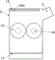
FIG. 2 is a sectional view of the waste treatment apparatus of the present invention;
FIG. 3 is a schematic side view of the waste treatment apparatus of the present invention;
fig. 4 is an enlarged schematic view of a portion a in fig. 1 according to the present invention.
In the figure: 1. a base plate; 2. a waste treatment device; 3. a feeding port; 4. a first motor; 5. a second motor; 6. cushion blocks; 7. a fixed seat; 8. an electric push rod; 801. pushing the plate; 9. a water pump; 10. a water tank; 1001. a water injection port; 1002. a threaded cap; 11. buckling; 1101. buckling blocks; 12. a control panel; 1201. a first motor switch key; 1202. a second motor switch key; 1203. a water pump switch key; 1204. a push rod switch key; 13. a drain pipe; 1301. a valve; 14. a water conduit; 1401. a spray port; 15. a roller; 16. a bearing; 17. a water-permeable sieve plate; 18. a discharge gate.
Detailed Description
The technical solutions in the embodiments of the present invention will be described clearly and completely with reference to the accompanying drawings in the embodiments of the present invention, and it is obvious that the described embodiments are only some embodiments of the present invention, not all embodiments. Based on the embodiments in the present invention, all other embodiments obtained by a person skilled in the art without creative work belong to the protection scope of the present invention.
In the description of the present invention, it should be noted that the terms "upper", "lower", "inner", "outer", "front end", "rear end", "both ends", "one end", "the other end" and the like indicate orientations or positional relationships based on the orientations or positional relationships shown in the drawings, and are only for convenience of description and simplification of description, but do not indicate or imply that the device or element to which the reference is made must have a specific orientation, be constructed in a specific orientation, and be operated, and thus, should not be construed as limiting the present invention. Furthermore, the terms "first" and "second" are used for descriptive purposes only and are not to be construed as indicating or implying relative importance.
In the description of the present invention, it is to be noted that, unless otherwise explicitly specified or limited, the terms "mounted," "disposed," "connected," and the like are to be construed broadly, and for example, "connected" may be either fixedly connected or detachably connected, or integrally connected; can be mechanically or electrically connected; they may be connected directly or indirectly through intervening media, or they may be interconnected between two elements. The specific meaning of the above terms in the present invention can be understood in specific cases to those skilled in the art.
Referring to fig. 1-4, the present invention provides an embodiment: a waste recovery processing device for building construction comprises a bottom plate 1, a first motor 4, a water tank 10, a roller 15 and a buckle 11; a water tank 10 is welded on one side of the top of a bottom plate 1, the water tank 10 is used for storing water, a water suction pump 9 is fixedly installed on one side, close to the water tank 10, of the top of the bottom plate 1 through bolts, an input end of the water suction pump 9 is fixedly connected with an output end of the bottom of one side of the water tank 10 through a guide pipe, the type of the water suction pump 9 is GD80-21, the water suction pump 9 is used for pumping water in the water tank 10 and then conveying the water to the inside of a water guide pipe 14 through the guide pipe, a cushion block 6 is arranged at a position, close to the water suction pump 9, of the top of the bottom plate 1, an electric push rod 8 is fixedly installed at the top of the cushion block 6 through a fixing seat 7, a push plate 801 is fixedly installed at the output end of the electric push rod 8, the electric push rod 8 is used for pushing the push plate 801 to push out processed accumulated waste, a waste treatment device 2 is arranged at a position, close to the cushion block 6, and the waste treatment device 2 is used for recycling waste generated in building construction, the inner top of the waste treatment device 2 is fixedly provided with a water guide pipe 14, the input end of the water guide pipe 14 is fixedly connected with the output end of a water pump 9 through a guide pipe, the bottom of the water guide pipe 14 is provided with equidistant spraying ports 1401, water enters the water guide pipe 14 and is sprayed out through the spraying ports 1401 to clean dust on waste materials, the top of one side, far away from the water pump 9, of the waste treatment device 2 is provided with a material inlet 3, construction waste materials enter the waste treatment device 2 from the material inlet 3, two groups of rollers 15 are rotatably arranged below the material inlet 3 at the inner top of the waste treatment device 2 through a bearing 16 and are used for crushing and grinding the waste materials, the front side of the waste treatment device 2 is fixedly provided with a first motor 4 and a second motor 5 through bolts at positions corresponding to the bearing 16, the first motor 4 and the second motor 5 are C15-43B0, the output ends of the first motor 4 and the second motor 5 are fixedly connected with one end of a group of bearings 16 through rotating shafts, the first motor 4 and the second motor 5 are used for driving two groups of rollers 15 to rotate relatively, a water permeable sieve plate 17 is welded at the position of the inner bottom of the waste treatment device 2, the water permeable sieve plate 17 is used for separating treated waste from muddy water, the push plate 801 extends into the waste treatment device 2, and the push plate 801 is positioned above the permeable sieve plate 17, one side of the waste treatment device 2 far away from the push plate 801 is fixedly provided with a discharge gate 18 through a hinge, the discharge gate 18 is opened, the waste on the water-permeable screen plate 17 is discharged from the discharge gate 18 under the push of the push plate 801, the discharge gate 18 corresponds to the permeable sieve plate 17, a control panel 12 is arranged on one side of the front bottom of the waste treatment device 2, and the control panel 12 is used for controlling the working state of the electric components in the device.
Further, a water filling port 1001 is arranged at the center of the top of the water tank 10, the water filling port 1001 facilitates the addition of water, a screw cap 1002 is arranged at the top of the water filling port 1001, and the screw cap 1002 is used for sealing the water tank 10.
Further, a first motor switch key 1201, a second motor switch key 1202 and a first motor switch key 1201 are respectively arranged at positions, close to the top, on the front side of the control panel 12, the first motor switch key 1201 is used for controlling the working state of the first motor 4, the second motor switch key 1202 is used for controlling the working state of the second motor 5, a water pump switch key 1203 and a push rod switch key 1204 are respectively arranged at positions, close to the bottom, on the front side of the control panel 12, the water pump switch key 1203 is used for controlling the working state of the water suction pump 9, and the push rod switch key 1204 is used for controlling the telescopic state of the electric push rod 8.
Further, the first motor 4 is electrically connected with the control panel 12 through a lead, the second motor 5 is electrically connected with the control panel 12 through a lead, the electric push rod 8 is electrically connected with the control panel 12 through a lead, and the water suction pump 9 is electrically connected with the control panel 12 through a lead.
Furthermore, buckles 11 are arranged at two ends of the front top of the discharge door 18, buckling blocks 1101 are arranged at positions corresponding to the buckles 11 at the bottom end of the side surface of the waste treatment device 2, and when the discharge door 18 is closed on the waste treatment device 2, the buckles 11 are buckled on the buckling blocks 1101 to be fixed.
Further, a drain pipe 13 is arranged on one side of the bottom of the front surface of the waste material treatment device 2, which is far away from the control panel 12, a valve 1301 is arranged on the surface of the drain pipe 13, the valve 1301 is unscrewed, and muddy water at the bottom in the waste material treatment device 2 is discharged from the drain pipe 13.
The working principle is as follows: when the device is used, the control panel 12 is connected with an external power supply through a lead, the first motor on-off key 1201, the second motor on-off key 1202 and the water pump on-off key 1203 control the first motor 4, the second motor 5 and the water pump 9 to work, then a person puts waste into the waste treatment device 2 through the material inlet 3, the first motor 4 and the second motor 5 drive the two groups of rollers 15 to rotate relatively to crush the waste, in the process, the water pump 9 conveys water in the water tank 10 into the water guide pipe 14 and sprays the water through the spraying opening 1401 to clean and remove dust from the waste, the washed and treated waste falls on the water permeable sieve plate 17, muddy water flows to the bottom through the water permeable sieve plate 17, after the waste treatment is finished, the discharge door 18 is opened, the push rod on-off key 1204 controls the electric push rod 8 to push the push plate 801, and the waste on the water permeable sieve plate 17 is discharged from the discharge door 18 by the push plate 801, then, the valve 1301 is opened, and the muddy water inside the waste treatment device 2 is discharged through the water discharge pipe 13.
The details of the present invention are well known to those skilled in the art.
Finally, it is to be noted that: the above embodiments are only used for illustrating the technical solutions of the present invention and not for limiting, and although the present invention has been described in detail with reference to the examples, it should be understood by those skilled in the art that the technical solutions of the present invention can be modified and replaced with equivalents without departing from the spirit and scope of the technical solutions of the present invention, which should be covered by the scope of the claims of the present invention.

Claims (6)

1.一种建筑施工用废料回收处理装置,包括底板(1)、第一电机(4)、水箱(10)、辊轮(15)、卡扣(11);其特征在于:所述底板(1)顶部的一侧固定安装有水箱(10),所述底板(1)顶部靠近水箱(10)的一侧固定安装有抽水泵(9),且抽水泵(9)的输入端通过导管与水箱(10)一侧底部的输出端固定连接,所述底板(1)顶部靠近抽水泵(9)的位置处设有垫块(6),所述垫块(6)的顶部通过固定座(7)固定安装有电动推杆(8),所述电动推杆(8)的输出端固定安装有推板(801),所述底板(1)顶部靠近垫块(6)的位置处设有废料处理装置(2),所述废料处理装置(2)的内顶部固定安装有导水管(14),且导水管(14)的输入端通过导管与抽水泵(9)的输出端固定连接,所述导水管(14)的底部设有等距的喷淋口(1401),所述废料处理装置(2)远离抽水泵(9)一侧的顶部设有入料口(3),所述废料处理装置(2)内顶部位于入料口(3)的下方通过轴承(16)转动安装有两组辊轮(15),所述废料处理装置(2)的正面与轴承(16)对应的位置处分别固定安装有第一电机(4)、第二电机(5),且第一电机(4)和第二电机(5)的输出端通过转动轴与轴承(16)的一端固定连接,所述废料处理装置(2)的内底部位置处固定安装有透水筛板(17),所述推板(801)延伸至废料处理装置(2)的内部,且推板(801)位于透水筛板(17)的上方,所述废料处理装置(2)远离推板(801)的一侧通过铰链固定安装有排料门(18),且排料门(18)与透水筛板(17)相对应,所述废料处理装置(2)正面底部的一侧设有控制面板(12)。1. A construction waste recycling and processing device, comprising a bottom plate (1), a first motor (4), a water tank (10), a roller (15), and a buckle (11); it is characterized in that: the bottom plate ( 1) A water tank (10) is fixedly installed on one side of the top, and a suction pump (9) is fixedly installed on the side of the top of the bottom plate (1) close to the water tank (10), and the input end of the suction pump (9) is connected to the The output end of the bottom of one side of the water tank (10) is fixedly connected, and the top of the bottom plate (1) is provided with a cushion block (6) at the position close to the suction pump (9), and the top of the cushion block (6) passes through the fixing seat ( 7) An electric push rod (8) is fixedly installed, and a push plate (801) is fixedly installed at the output end of the electric push rod (8). A waste treatment device (2), a water conduit (14) is fixedly installed on the inner top of the waste treatment device (2), and the input end of the water conduit (14) is fixedly connected to the output end of the suction pump (9) through the conduit, The bottom of the water conduit (14) is provided with equidistant spray ports (1401), and the top of the waste treatment device (2) away from the suction pump (9) is provided with a feed port (3). The inner top of the waste treatment device (2) is located below the feed port (3) and is rotatably installed with two sets of rollers (15) through the bearing (16). The front of the waste treatment device (2) corresponds to the bearing (16). A first motor (4) and a second motor (5) are respectively fixedly installed at the positions, and the output ends of the first motor (4) and the second motor (5) are fixedly connected to one end of the bearing (16) through a rotating shaft, A permeable screen plate (17) is fixedly installed at the inner bottom position of the waste treatment device (2), the push plate (801) extends to the interior of the waste treatment device (2), and the push plate (801) is located in the permeable screen Above the plate (17), a discharge door (18) is fixedly installed on the side of the waste treatment device (2) away from the push plate (801) through a hinge, and the discharge door (18) is connected to the permeable screen plate (17) Correspondingly, a control panel (12) is provided on one side of the bottom of the front of the waste disposal device (2). 2.根据权利要求1所述的一种建筑施工用废料回收处理装置,其特征在于:所述水箱(10)的顶部中央位置处设有注水口(1001),所述注水口(1001)的顶部设有螺纹盖(1002)。2. A construction waste recycling and processing device according to claim 1, characterized in that: a water injection port (1001) is provided at the central position of the top of the water tank (10), and the water injection port (1001) has a Top with screw cap (1002). 3.根据权利要求1所述的一种建筑施工用废料回收处理装置,其特征在于:所述控制面板(12)正面靠近顶部的位置处分别设有一号电机开关键(1201)、二号电机开关键(1202)、所述控制面板(12)正面靠近底部的位置处分别设有水泵开关键(1203)、推杆开关键(1204)。3. A construction waste recycling and processing device according to claim 1, wherein the control panel (12) is provided with a No. 1 motor switch key (1201) and a No. 2 motor at the position close to the top of the control panel (12). The switch key (1202) and the position on the front of the control panel (12) close to the bottom are respectively provided with a water pump switch key (1203) and a push rod switch key (1204). 4.根据权利要求1所述的一种建筑施工用废料回收处理装置,其特征在于:所述第一电机(4)通过导线与控制面板(12)电性连接,所述第二电机(5)通过导线和控制面板(12)电性连接,所述电动推杆(8)通过导线与控制面板(12)电性连接,所述抽水泵(9)通过导线与控制面板(12)电性连接。4. A construction waste recycling and processing device according to claim 1, characterized in that: the first motor (4) is electrically connected to the control panel (12) through wires, and the second motor (5) is electrically connected to the control panel (12). ) is electrically connected to the control panel (12) through wires, the electric push rod (8) is electrically connected to the control panel (12) through wires, and the suction pump (9) is electrically connected to the control panel (12) through wires connect. 5.根据权利要求1所述的一种建筑施工用废料回收处理装置,其特征在于:所述排料门(18)的正面顶部两端处设有卡扣(11),所述废料处理装置(2)的侧面底端与卡扣(11)相应的位置处设有扣块(1101)。5 . The construction waste recycling and processing device according to claim 1 , wherein the two ends of the front top of the discharge door ( 18 ) are provided with buckles ( 11 ), and the waste processing device A buckle block (1101) is provided at a position corresponding to the bottom end of the side surface of (2) and the buckle (11). 6.根据权利要求1所述的一种建筑施工用废料回收处理装置,其特征在于:所述废料处理装置(2)正面底部远离控制面板(12)的一侧设有排水管(13),且排水管(13)的表面设有阀门(1301)。6. A construction waste recycling and processing device according to claim 1, characterized in that: a drain pipe (13) is provided on the side of the front bottom of the waste processing device (2) away from the control panel (12), And the surface of the drain pipe (13) is provided with a valve (1301).
CN202022701024.3U 2020-11-20 2020-11-20 A construction waste recycling and processing device Expired - Fee Related CN213914012U (en)

Priority Applications (1)

Application Number Priority Date Filing Date Title
CN202022701024.3U CN213914012U (en) 2020-11-20 2020-11-20 A construction waste recycling and processing device

Applications Claiming Priority (1)

Application Number Priority Date Filing Date Title
CN202022701024.3U CN213914012U (en) 2020-11-20 2020-11-20 A construction waste recycling and processing device

Publications (1)

Publication Number Publication Date
CN213914012U true CN213914012U (en) 2021-08-10

Family

ID=77172343

Family Applications (1)

Application Number Title Priority Date Filing Date
CN202022701024.3U Expired - Fee Related CN213914012U (en) 2020-11-20 2020-11-20 A construction waste recycling and processing device

Country Status (1)

Country Link
CN (1) CN213914012U (en)

Similar Documents

Publication Publication Date Title
CN212189307U (en) Recycled aggregate crushing, screening and cleaning device
CN212284235U (en) Building rubbish reducing mechanism with dust removal function
CN213914012U (en) A construction waste recycling and processing device
CN212741684U (en) Garbage collection device is used in textile fabric production
CN210586077U (en) Hardware sheet cleaning device
CN220995121U (en) Fluoroplastic efficient recycling device
CN207738975U (en) A kind of weaving cleaning machine of Rapid Cleaning
CN217830170U (en) High-purity quartz sand production device
CN218360958U (en) Energy-concerving and environment-protective type steel scrap tails secondary washing recovery unit
CN214234248U (en) Building rubbish handles dust keeper
CN216910502U (en) Broken stone crushing device for mining
CN216856935U (en) Building waste breaker
CN219682653U (en) Crushing device for recycling waste copper
CN112846856A (en) Machining is with cutting belt cleaning device who has garbage collection structure
CN212792115U (en) High-efficient roll formula washing medicine machine
CN213625511U (en) A kind of water and grass cleaning device for river management
CN222220506U (en) Malt granule belt cleaning device is used in malt beer production
CN218796118U (en) Building construction grit breaker
CN214487079U (en) Construction waste treatment device
CN221789623U (en) Sand washer for recycling construction waste
CN223209540U (en) Mortar raw stone breaker
CN222153082U (en) Device for cleaning ores
CN215543050U (en) Metal chip processing and recycling device
CN215236244U (en) Electronic ceramic waste recovery device
CN213102430U (en) Environment-friendly construction waste treatment facility

Legal Events

Date Code Title Description
GR01 Patent grant
GR01 Patent grant
CF01 Termination of patent right due to non-payment of annual fee

Granted publication date: 20210810

CF01 Termination of patent right due to non-payment of annual fee