CN213920117U - Printing roller of printing machine - Google Patents
Printing roller of printing machine Download PDFInfo
- Publication number
- CN213920117U CN213920117U CN202021959979.2U CN202021959979U CN213920117U CN 213920117 U CN213920117 U CN 213920117U CN 202021959979 U CN202021959979 U CN 202021959979U CN 213920117 U CN213920117 U CN 213920117U
- Authority
- CN
- China
- Prior art keywords
- printing machine
- printing
- bin body
- bottom end
- connecting block
- Prior art date
- Legal status (The legal status is an assumption and is not a legal conclusion. Google has not performed a legal analysis and makes no representation as to the accuracy of the status listed.)
- Active
Links
- 238000007639 printing Methods 0.000 title claims abstract description 107
- XLYOFNOQVPJJNP-UHFFFAOYSA-N water Substances O XLYOFNOQVPJJNP-UHFFFAOYSA-N 0.000 claims abstract description 35
- 238000004140 cleaning Methods 0.000 claims abstract description 15
- 230000007246 mechanism Effects 0.000 claims abstract description 15
- 239000007921 spray Substances 0.000 claims description 10
- 239000007788 liquid Substances 0.000 abstract description 17
- 239000012535 impurity Substances 0.000 abstract description 10
- 238000005406 washing Methods 0.000 abstract description 4
- 230000000694 effects Effects 0.000 description 4
- 239000000976 ink Substances 0.000 description 4
- 239000012459 cleaning agent Substances 0.000 description 2
- 238000001914 filtration Methods 0.000 description 2
- 238000000034 method Methods 0.000 description 2
- 230000009286 beneficial effect Effects 0.000 description 1
- 238000007599 discharging Methods 0.000 description 1
- 239000004744 fabric Substances 0.000 description 1
- 238000010020 roller printing Methods 0.000 description 1
- 239000013049 sediment Substances 0.000 description 1
- 238000003756 stirring Methods 0.000 description 1
- 239000002699 waste material Substances 0.000 description 1
Images


Landscapes
- Inking, Control Or Cleaning Of Printing Machines (AREA)
Abstract
The utility model relates to a printing machine technical field specifically is a printing roller of printing machine, including printing machine main part and first water pump, the internally mounted of printing machine main part has printing roller main part, the right-hand member of printing machine main part is provided with wiper mechanism, the bottom of printing machine main part is provided with the third storehouse body, the left and right sides of third storehouse internal wall is fixed with the third connecting block, the inside of the third storehouse body is provided with first filter screen. The utility model discloses the workman is to printing roller main part surface cleaning's efficiency has been improved greatly for printing roller main part's surface is cleaner more, makes the inside inking of printing roller main part and play black more rapidly, and the product that prints out accords with the standard more, makes the workman to the clearance convenience more of impurity, makes the workman handle to the mixed liquid after the washing more convenient, thereby has wholly improved workman's work efficiency, has practiced thrift workman's operating time greatly.
Description
Technical Field
The utility model relates to a printing machine technical field specifically is a printing roller of printing machine.
Background
With the rapid development of the economy in China, the rapid development of the printing industry in China is promoted, some printing factories in China begin to introduce some advanced devices for printing, rubber roller printing rollers begin to be assembled on some printing machines, the printing efficiency is higher, the printing effect is better, however, in the printing process, some residual impurities are accumulated on the surfaces of the rubber rollers, the residues are accumulated in holes for a long time, under the action of printing pressure and heat, the surfaces of the printing rollers are finally glazed, the printing rollers need to be cleaned regularly, the existing printing machines are not provided with mechanisms for cleaning the printing rollers, usually some cloths are taken by workers for wiping, the working efficiency is slower, the cleaning effect on the printing rollers is not good, the printing work of the printing rollers of the printing machines is influenced, and the working efficiency of the printing machines is reduced, so that the printing effect cannot meet the standard requirement.
SUMMERY OF THE UTILITY MODEL
An object of the utility model is to provide a printing roller of printing machine to current printing machine that proposes in solving above-mentioned background art does not carry out abluent mechanism to the printing roller, all is taking some cloth to clean through the workman usually, and work efficiency is slower, and makes the cleaning performance to the printing roller also not comparatively good, influences the printing work of printing machine printing roller, thereby has reduced the work efficiency of printing machine, makes the printing effect can not reach the problem that the standard required.
In order to achieve the above object, the utility model provides a following technical scheme: a printing roller of a printing machine comprises a printing machine main body and a first water pump, wherein the printing roller main body is installed inside the printing machine main body, a cleaning mechanism is arranged at the right end of the printing machine main body and comprises a first bin body, a first bin body is fixed at the right end of the printing machine main body, a first opening is formed in the top end of the first bin body, a first closed cover is sleeved outside the first opening, a first rotating handle is arranged in the middle of the first bin body, the upper end and the lower end of the first rotating handle are connected with the first bin body through bearings, the top end of the first rotating handle penetrates through the inner wall of the first bin body and extends to the outside of the first bin body, a second bin body is fixed at the bottom end of the first bin body and is communicated with the bottom end of the first bin body, the first water pump is installed at the bottom end of the right side of the printing machine main body, a first connecting pipe is installed at the top end of the first water pump, the top end of a first connecting pipe is communicated with the bottom end of a second bin body, a first valve is installed on the outer side of the top end of the first connecting pipe, a first connecting block is fixed on the right side of the first bin body, a first groove is formed in the first connecting block, a second connecting block is arranged at the top end of the first connecting block, a first connecting rod is inserted into the second connecting block, the bottom end of the first connecting rod is connected with the first connecting block through a bearing, the top end of the first connecting rod is connected with the second connecting block through a bearing, a second connecting pipe is inserted into the middle of the first groove, the bottom end of the second connecting pipe is communicated with a first water pump, a first spray nozzle is installed at the top end of the second connecting pipe, a collecting mechanism is arranged at the bottom end of the printer main body and comprises a third bin body, and a third bin body is arranged at the bottom end of the printer main body, the left and right sides of the inner wall of the third bin body is fixed with a third connecting block, the inside of the third bin body is provided with a first filter screen, the left and right ends of the first filter screen are inserted into the third connecting block, the left and right ends of the first filter screen are fixed with second connecting rods, a first water outlet is formed in the bottom of the right side of the third bin body, a second valve is installed outside the first water outlet, the bottom of the third bin body is provided with a fourth connecting block, and the left and right ends of the fourth connecting block are inserted into grooves formed in the bottom end of the printing machine main body.
Preferably, the surface of the top end of the first rotating handle is glued with a first rubber pad, and the first rubber pad is attached to the surface of the first rotating handle.
Preferably, the outer side of the first rotating handle is fixed with connecting rods, and the connecting rods are uniformly distributed on the surface of the first rotating handle.
Preferably, the longitudinal section of the first bin body is rectangular, and the bottom end of the first bin body is inclined.
Preferably, the bottom end of the first water pump is fixedly connected with the connecting block, and the connecting block is fixedly connected with the printing machine main body.
Preferably, the longitudinal section of the third bin body is rectangular, and the bottom end of the third bin body is inclined.
Compared with the prior art, the beneficial effects of the utility model are that: the utility model discloses improved workman's efficiency to printing roller main part surface cleaning greatly, made the surface of printing roller main part cleaner, made the inking and the play china ink of printing roller main part inside more rapid, the product that prints out more accords with the standard, made the workman more convenient to the clearance of impurity, made the workman handle the mixed liquid after the washing more convenient, thereby wholly improved workman's work efficiency, practiced thrift workman's operating time greatly;
1. the first rotating handle and the first spray head are arranged, a worker needs to clean the surface of the printing roller body to a certain extent after the work of the printing machine body is finished, the worker firstly opens the first closing cover, a certain amount of cleaning agent is injected into the first bin body, then clean water in proportion is injected into the first bin body, the first rotating handle is continuously rotated by workers, the cleaning agent and the clear water are stirred and mixed, and after a period of mixing, workers carry out external power supply on the first water pump, the surface of the printing roller main body is cleaned to a certain degree by picking up the first spray head, so that the surface of the printing roller main body is cleaned, the efficiency of cleaning the surface of the printing roller main body by workers is greatly improved, the surface of the printing roller main body is cleaner, the inking and ink discharging inside the printing roller main body are quicker, and the printed product meets the standard better;
2. be provided with first filter screen and the third storehouse body, when the workman washes printing roller main part, the impurity such as china ink skin and china ink sediment on printing roller main part surface can flow into the third storehouse internal portion along with the washing liquid together, be provided with first filter screen through the third storehouse internal portion, can carry out certain filtration to the impurity in mixing the liquid, make the workman more convenient to the clearance of impurity, make the workman handle the mixed liquid after the washing more conveniently, thereby wholly improved workman's work efficiency, workman's operating time has been practiced thrift greatly.
Drawings
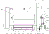
FIG. 1 is a schematic sectional view of the front view of the structure of the present invention;
fig. 2 is an enlarged schematic view of the structure a in fig. 1 according to the present invention;
fig. 3 is an enlarged schematic view of the structure B in fig. 1 according to the present invention;
fig. 4 is a schematic view of the front view of the structure of the present invention.
In the figure: 100. a printer main body; 111. a printing roller main body; 200. a cleaning mechanism; 210. a first bin body; 211. a first opening; 212. a first closure cap; 213. a first rotating handle; 214. a second bin body; 215. a first water pump; 216. a first connecting pipe; 217. a first valve; 218. a first connection block; 219. a first groove; 220. a second connecting block; 221. a first connecting rod; 222. a second connecting pipe; 223. a first nozzle; 300. a collection mechanism; 310. a third bin body; 311. a third connecting block; 312. a first filter screen; 313. a second connecting rod; 314. a first water outlet; 315. a second valve; 316. and a fourth connecting block.
Detailed Description
The technical solutions in the embodiments of the present invention will be described clearly and completely with reference to the accompanying drawings in the embodiments of the present invention, and it is obvious that the described embodiments are only some embodiments of the present invention, not all embodiments. Based on the embodiments in the present invention, all other embodiments obtained by a person skilled in the art without creative work belong to the protection scope of the present invention.
Referring to fig. 1-4, the present invention provides an embodiment:
a printing roller of a printing machine comprises a printing machine main body 100 and a first water pump 215, a printing roller main body 111 is installed inside the printing machine main body 100, a cleaning mechanism 200 is arranged at the right end of the printing machine main body 100, the cleaning mechanism 200 comprises a first bin body 210, a first bin body 210 is fixed at the right end of the printing machine main body 100, a first opening 211 is formed in the top end of the first bin body 210, a first closed cover 212 is sleeved outside the first opening 211, a first rotating handle 213 is arranged in the middle of the first bin body 210, the upper end and the lower end of the first rotating handle 213 are connected with the first bin body 210 through bearings, the top end of the first rotating handle 213 penetrates through the inner wall of the first bin body 210 and extends to the outside of the first bin body 210, a second bin body 214 is fixed at the bottom end of the first bin body 210, the second bin body 214 is communicated with the bottom end of the first bin body 210, a first water pump 215 is installed at the bottom end of the right side of the printing machine main body 100, a first connecting pipe 216 is installed at the top end of the first water pump 215, the top end of the first connecting pipe 216 is communicated with the bottom end of the second cabin body 214, the outer side of the top end of the first connecting pipe 216 is provided with a first valve 217, the right side of the first cabin body 210 is fixed with a first connecting block 218, the inside of the first connecting block 218 is provided with a first groove 219, the top end of the first connecting block 218 is provided with a second connecting block 220, the inside of the second connecting block 220 is inserted with a first connecting rod 221, the bottom end of the first connecting rod 221 is connected with the first connecting block 218 through a bearing, the top end of the first connecting rod 221 is connected with the second connecting block 220 through a bearing, the middle part of the first groove 219 is inserted with a second connecting pipe 222, the bottom end of the second connecting pipe 222 is communicated with a first water pump 215, the top end of the second connecting pipe 222 is provided with a first spray head 223, the bottom end of the printer main body 100 is provided with a collecting mechanism 300, the collecting mechanism 300 comprises a third cabin body 310, the bottom end of the printer main body 100 is provided with the third cabin body 310, third connecting blocks 311 are fixed on the left side and the right side of the inner wall of the third cabin body 310, a first filter screen 312 is arranged inside the third cabin body 310, the left end and the right end of the first filter screen 312 are inserted into the third connecting blocks 311, second connecting rods 313 are fixed on the left end and the right end of the first filter screen 312, a first water outlet 314 is formed in the bottom end of the right side of the third cabin body 310, a second valve 315 is installed outside the first water outlet 314, a fourth connecting block 316 is arranged at the bottom end of the third cabin body 310, and the left end and the right end of the fourth connecting block 316 are inserted into a groove in the bottom end of the printer main body 100;
furthermore, the first rubber pad is glued on the surface of the top end of the first rotating handle 213, and the first rubber pad is attached to the surface of the first rotating handle 213, so that the friction between the hand of a worker and the surface of the first rotating handle 213 is increased, and the worker can exert force more conveniently;
furthermore, a connecting rod is fixed on the outer side of the first rotating handle 213, and the connecting rod is uniformly distributed on the surface of the first rotating handle 213, so that the mixed liquid in the first bin body 210 is stirred more fully;
further, the longitudinal section of the first bin body 210 is rectangular, and the bottom end of the first bin body 210 is inclined, so that the mixed liquid in the first bin body 210 can more rapidly flow into the second bin body 214;
further, a connecting block is fixed at the bottom end of the first water pump 215, and the connecting block is fixedly connected with the printing machine main body 100, so that the first water pump 215 is more stable in operation;
further, the longitudinal section of the third chamber body 310 is rectangular, and the bottom end of the third chamber body 310 is inclined, so that the waste liquid inside the third chamber body 310 can flow into the first water outlet 314 more quickly.
The working principle is as follows: firstly, after the printing machine main body 100 is used for a period of time, the surface of the printing roller main body 111 needs to be cleaned to a certain extent, so that the printing roller main body 111 can work better, a worker carries out an external power supply on the first water pump 215, the worker rotates the first closing cover 212 to separate the first closing cover 212 from the first opening 211, so as to open the first bin body 210, appropriate cleaning liquid is injected into the first bin body 210, clean water in proportion is injected into the first bin body 210, then the worker rotates the first rotating handle 213 to stir the cleaning liquid and the clean water in the first bin body 210 to a certain extent, the cleaning liquid and the clean water are mixed uniformly through the continuous rotation of the worker, then the worker rotates the second connecting block 220 to separate the second connecting block 220 from the first spray nozzle 223, so that the worker can start the first spray nozzle 223 from the inside of the first groove 219, a worker opens the first valve 217, works through the first water pump 215, so that the mixed liquid in the first bin body 210 enters the second connecting pipe 222, the worker takes up the first spray head 223, the mixed liquid in the second connecting pipe 222 enters the first spray head 223, and the worker cleans the surface of the printing roller main body 111 to a certain extent through the mixed liquid sprayed from the first spray head 223;
in abluent in-process, there is a large amount of mixed liquid that contains impurity to flow into the third storehouse body 310 inside that printing roller main part 111 bottom set up, carry out certain filtration through the inside impurity that is provided with first filter screen 312 in the third storehouse body 310 to mixed liquid for the workman is better handles impurity, avoid impurity and water to mix and pour into the field and cause certain pollution to natural environment, the user opens second valve 315, discharge the mixed liquid of the inside of third storehouse body 310 through first delivery port 314.
It is obvious to a person skilled in the art that the invention is not restricted to details of the above-described exemplary embodiments, but that it can be implemented in other specific forms without departing from the spirit or essential characteristics of the invention. The present embodiments are therefore to be considered in all respects as illustrative and not restrictive, the scope of the invention being indicated by the appended claims rather than by the foregoing description, and all changes which come within the meaning and range of equivalency of the claims are therefore intended to be embraced therein. Any reference sign in a claim should not be construed as limiting the claim concerned.
Claims (6)
1. A printing roller of a printing press comprising a printing press main body (100) and a first water pump (215), characterized in that: the printing machine is characterized in that a printing roller main body (111) is installed inside the printing machine main body (100), a cleaning mechanism (200) is arranged at the right end of the printing machine main body (100), the cleaning mechanism (200) comprises a first bin body (210), a first bin body (210) is fixed at the right end of the printing machine main body (100), a first opening (211) is formed in the top end of the first bin body (210), a first closed cover (212) is sleeved outside the first opening (211), a first rotating handle (213) is arranged in the middle of the first bin body (210), the upper end and the lower end of the first rotating handle (213) are connected with the first bin body (210) through bearings, the top end of the first rotating handle (213) penetrates through the inner wall of the first bin body (210) and extends to the outside of the first bin body (210), a second bin body (214) is fixed at the bottom end of the first bin body (210), and the second bin body (214) is communicated with the bottom end of the first bin body (210), the printing machine is characterized in that a first water pump (215) is installed at the bottom end of the right side of the printing machine main body (100), a first connecting pipe (216) is installed at the top end of the first water pump (215), the top end of the first connecting pipe (216) is communicated with the bottom end of a second cabin body (214), a first valve (217) is installed on the outer side of the top end of the first connecting pipe (216), a first connecting block (218) is fixed on the right side of the first cabin body (210), a first groove (219) is formed in the first connecting block (218), a second connecting block (220) is arranged at the top end of the first connecting block (218), a first connecting rod (221) is inserted into the second connecting block (220), the bottom end of the first connecting rod (221) is connected with the first connecting block (218) through a bearing, and the top end of the first connecting rod (221) is connected with the second connecting block (220) through a bearing, a second connecting pipe (222) is inserted in the middle of the first groove (219), the bottom end of the second connecting pipe (222) is communicated with a first water pump (215), a first spray head (223) is installed at the top end of the second connecting pipe (222), a collecting mechanism (300) is arranged at the bottom end of the printing machine main body (100), the collecting mechanism (300) comprises a third bin body (310), a third bin body (310) is arranged at the bottom end of the printing machine main body (100), third connecting blocks (311) are fixed on the left side and the right side of the inner wall of the third bin body (310), a first filter screen (312) is arranged inside the third bin body (310), the left end and the right end of the first filter screen (312) are inserted into the third connecting blocks (311), second connecting rods (313) are fixed on the left end and the right end of the first filter screen (312), and a first water outlet (314) is formed in the bottom end of the right side of the third bin body (310), and a second valve (315) is installed on the outer side of the first water outlet (314), a fourth connecting block (316) is arranged at the bottom end of the third cabin body (310), and the left end and the right end of the fourth connecting block (316) are inserted into grooves formed in the bottom end of the printing machine main body (100).
2. The printing roller of a printing machine according to claim 1, characterized in that: the surface of the top end of the first rotating handle (213) is glued with a first rubber pad, and the first rubber pad is attached to the surface of the first rotating handle (213).
3. The printing roller of a printing machine according to claim 1, characterized in that: the outer side of the first rotating handle (213) is fixed with connecting rods, and the connecting rods are uniformly distributed on the surface of the first rotating handle (213).
4. The printing roller of a printing machine according to claim 1, characterized in that: the longitudinal section of the first bin body (210) is rectangular, and the bottom end of the first bin body (210) is inclined.
5. The printing roller of a printing machine according to claim 1, characterized in that: the bottom end of the first water pump (215) is fixedly connected with the connecting block, and the connecting block is fixedly connected with the printing machine main body (100).
6. The printing roller of a printing machine according to claim 1, characterized in that: the longitudinal section of the third cabin body (310) is rectangular, and the bottom end of the third cabin body (310) is inclined.
Priority Applications (1)
| Application Number | Priority Date | Filing Date | Title |
|---|---|---|---|
| CN202021959979.2U CN213920117U (en) | 2020-09-09 | 2020-09-09 | Printing roller of printing machine |
Applications Claiming Priority (1)
| Application Number | Priority Date | Filing Date | Title |
|---|---|---|---|
| CN202021959979.2U CN213920117U (en) | 2020-09-09 | 2020-09-09 | Printing roller of printing machine |
Publications (1)
| Publication Number | Publication Date |
|---|---|
| CN213920117U true CN213920117U (en) | 2021-08-10 |
Family
ID=77160847
Family Applications (1)
| Application Number | Title | Priority Date | Filing Date |
|---|---|---|---|
| CN202021959979.2U Active CN213920117U (en) | 2020-09-09 | 2020-09-09 | Printing roller of printing machine |
Country Status (1)
| Country | Link |
|---|---|
| CN (1) | CN213920117U (en) |
-
2020
- 2020-09-09 CN CN202021959979.2U patent/CN213920117U/en active Active
Similar Documents
| Publication | Publication Date | Title |
|---|---|---|
| CN108523795B (en) | Cleaning structure and cleaning tool for flat mop | |
| CN217287876U (en) | Ship boiler gas carbon neutralization device | |
| CN210314875U (en) | Automatic change printing and dyeing roller cleaning device for spinning machine | |
| CN211195439U (en) | Scraper device for ink roller of printing machine | |
| CN108580371B (en) | Double-sided cleaning device for flat castings | |
| CN114431795B (en) | Hand-held type glass curtain wall cleaning device | |
| CN107498995A (en) | A kind of hairbrush roll-type cleaning device of offset press | |
| CN218486792U (en) | Waste gas collecting mechanism of transfer printing machine | |
| CN219769419U (en) | Cleaning structure of printing roller | |
| CN208448821U (en) | A kind of power distribution cabinet filter screen cleaner | |
| CN217773363U (en) | Water-saving emission-reducing cleaning device for spray dryer | |
| CN208178033U (en) | One kind being used for large-tonnage ink transfer cylinder self-cleaning circulating device | |
| CN116463802A (en) | Recycling bleaching plant for waste textiles | |
| CN111907210B (en) | Single scraper device of printing unit of carton printing groover | |
| CN214289630U (en) | Lampshade outer wall cleaning device for glass cover production | |
| CN213627252U (en) | Hollow glass window with self-cleaning mechanism | |
| CN210905295U (en) | Air filter cloth belt cleaning device | |
| CN207496255U (en) | The hairbrush roll-type cleaning device of offset press | |
| CN208944713U (en) | A kind of follow-on plastic products cleaning device | |
| CN215466405U (en) | 3D prints with placing platform convenient to clearance | |
| CN205573328U (en) | Efficient water conservation's circular screen printer conduction band belt cleaning device | |
| CN221562583U (en) | Novel equipment for automatically cleaning screen printing plate | |
| CN222550303U (en) | A filtering device for water-based paint production | |
| CN213260468U (en) | Rubber welt mill is with high-efficient cleaning device with water conservation function | |
| CN222642820U (en) | Polluted soil leaching device |
Legal Events
| Date | Code | Title | Description |
|---|---|---|---|
| GR01 | Patent grant | ||
| GR01 | Patent grant |