CN213920834U - Lighting Systems and Vehicles - Google Patents
Lighting Systems and Vehicles Download PDFInfo
- Publication number
- CN213920834U CN213920834U CN202022981511.XU CN202022981511U CN213920834U CN 213920834 U CN213920834 U CN 213920834U CN 202022981511 U CN202022981511 U CN 202022981511U CN 213920834 U CN213920834 U CN 213920834U
- Authority
- CN
- China
- Prior art keywords
- light
- thick
- connecting plate
- reflecting surface
- reflector
- Prior art date
- Legal status (The legal status is an assumption and is not a legal conclusion. Google has not performed a legal analysis and makes no representation as to the accuracy of the status listed.)
- Active
Links
Images
Classifications
-
- F—MECHANICAL ENGINEERING; LIGHTING; HEATING; WEAPONS; BLASTING
- F21—LIGHTING
- F21S—NON-PORTABLE LIGHTING DEVICES; SYSTEMS THEREOF; VEHICLE LIGHTING DEVICES SPECIALLY ADAPTED FOR VEHICLE EXTERIORS
- F21S43/00—Signalling devices specially adapted for vehicle exteriors, e.g. brake lamps, direction indicator lights or reversing lights
- F21S43/40—Signalling devices specially adapted for vehicle exteriors, e.g. brake lamps, direction indicator lights or reversing lights characterised by the combination of reflectors and refractors
- F21S43/401—Signalling devices specially adapted for vehicle exteriors, e.g. brake lamps, direction indicator lights or reversing lights characterised by the combination of reflectors and refractors the refractors and the reflectors being distinct parts
Landscapes
- Engineering & Computer Science (AREA)
- General Engineering & Computer Science (AREA)
- Non-Portable Lighting Devices Or Systems Thereof (AREA)
Abstract
The utility model relates to a car light technical field especially relates to a car light system. The vehicle lamp system comprises a reflecting cover, a lamp panel, a thick-wall part and a light homogenizing part; the reflector is provided with a reflecting surface which is obliquely arranged, and one side of the thick-wall part is opposite to the reflecting surface and is arranged at intervals; the lamp panel is provided with a plurality of light-emitting pieces, and the light-emitting directions of the light-emitting pieces face the light-reflecting surface so that the light-reflecting surface reflects at least part of light rays emitted by the light-emitting pieces to one side of the thick-wall piece; the light homogenizing member is positioned between the thick-walled member and the light reflecting surface to homogenize light reflected from the light reflecting surface toward the thick-walled member. The light homogenizing element has the ability to homogenize the light. When the light transmits through the light homogenizing piece, the light can be subjected to diffuse reflection on and/or in the light homogenizing piece, so that the light is homogenized, and after the homogenized light is emitted into the thick-wall piece, the other side of the thick-wall piece presents uniform light and has more suspension feeling, so that the visual impression is improved. The utility model also provides a vehicle.
Description
Technical Field
The utility model relates to a car light technical field especially relates to a car light system and vehicle.
Background
At present, when the vehicle lamps of a plurality of vehicles are lighted, the light-emitting ends of the thick-wall parts can show the condition of alternating brightness and darkness, namely, the light distribution is uneven, so that the visual impression of the position lamps is poor.
SUMMERY OF THE UTILITY MODEL
An object of the utility model is to provide a promote car light system and vehicle of even light effect.
The vehicle lamp system comprises a reflecting cover, a lamp panel, a thick-wall part and a light homogenizing part; the reflector is provided with a reflecting surface which is obliquely arranged, and one side of the thick-wall part is opposite to the reflecting surface and is arranged at intervals; the lamp panel is provided with a plurality of light-emitting pieces, and the light-emitting directions of the light-emitting pieces face the light-reflecting surface so that the light-reflecting surface reflects at least part of light rays emitted by the light-emitting pieces to one side of the thick-wall piece; the light homogenizing member is positioned between the thick-walled member and the light reflecting surface to homogenize light reflected from the light reflecting surface toward the thick-walled member.
Optionally, the reflector includes a reflector and a first connecting plate, and one surface of the reflector facing the thick-walled member is formed as a light reflecting surface; the first connecting plate is positioned between the light reflecting surface and the lamp panel; the first connecting plate is provided with a plurality of light through holes penetrating through the first connecting plate, and one light through hole at least corresponds to one light-emitting piece, so that light rays emitted by the light-emitting piece are emitted to the light reflecting surface through the light through holes.
Optionally, one end of the first connecting plate is connected with one end of the reflector, and the other end of the first connecting plate is connected with the side wall of the thick-walled member; the first connecting plate is provided with a mounting groove facing the light homogenizing piece, and one end of the light homogenizing piece is mounted in the mounting groove.
Optionally, a first connecting portion protruding from the thick-walled member is arranged on the side wall of the thick-walled member; a first interval is arranged between the lamp panel and the thick-walled part; the other end of the first connecting plate extends outwards from the first interval and is attached to the first connecting part; the mounting slots are located between the first spaces.
Optionally, the reflector further includes a second connecting plate, and the second connecting plate is arranged opposite to the first connecting plate; one end of the second connecting plate is connected with the other end of the reflector, and the other end of the second connecting plate is connected with the side wall of the thick-wall part; the other end of the light homogenizing piece is provided with an extension part extending outwards, and the extension part is pressed against one surface of the second connecting plate facing the first connecting plate.
Optionally, one end of the second connecting plate is bent towards the other end of the reflector; one end of the extending part is pressed against the bending part at one end of the second connecting plate.
Optionally, a second interval is formed between the side wall of the thick-wall part and the second connecting plate, and the interval size of the second interval is larger than the thickness size of the extending part.
Optionally, the light homogenizing piece is a light-transmitting milky white board or a transparent board with patterns on the surface.
Optionally, the other side of the thick-walled member has a frosted surface.
The vehicle comprises the lamp system of any one of the embodiments.
The embodiment of the utility model provides a technical scheme compares with prior art and has following advantage:
the light homogenizing element has the ability to homogenize the light. When the light transmits through the light homogenizing piece, the light can be subjected to diffuse reflection on and/or in the light homogenizing piece, so that the light is homogenized, and after the homogenized light is emitted into the thick-wall piece, the other side of the thick-wall piece presents uniform light and has more suspension feeling, so that the visual impression is improved.
Drawings
The accompanying drawings, which are incorporated in and constitute a part of this specification, illustrate embodiments consistent with the invention and together with the description, serve to explain the principles of the invention.
In order to more clearly illustrate the embodiments of the present invention or the technical solutions in the prior art, the drawings used in the description of the embodiments or the prior art will be briefly described below, and it is obvious for those skilled in the art that other drawings can be obtained according to the drawings without inventive labor.
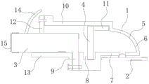
Fig. 1 is a schematic view of a vehicle lamp system according to an embodiment of the present invention.
Wherein, 1, a reflector; 2. a lamp panel; 3. a thick-walled member; 4. a light homogenizing piece; 5. a light-reflecting surface; 6. a reflector; 7. a first connecting plate; 8. mounting grooves; 9. a first connection portion; 10. a second connecting plate; 11. an extension portion; 12. a second connecting portion; 13. a lower decorative plate; 14. an upper decorative plate; 15. and (5) sanding.
Detailed Description
In order that the above objects, features and advantages of the present invention may be more clearly understood, the aspects of the present invention will be further described below. It should be noted that the embodiments and features of the embodiments of the present invention may be combined with each other without conflict.
In the following description, numerous specific details are set forth in order to provide a thorough understanding of the present invention, but the invention may be practiced in other ways than those described herein; obviously, the embodiments in the specification are only a part of the embodiments of the present invention, and not all of the embodiments.
As shown in fig. 1, the utility model provides a car light system, it includes reflector 1, lamp plate 2, thick walled member 3 and dodging 4. The reflector 1 has a reflecting surface 5 disposed obliquely, and one side of the thick-walled member 3 is disposed opposite to and spaced apart from the reflecting surface 5. Have a plurality of illuminating parts on the lamp plate 2, the light-emitting direction of illuminating part is towards reflection of light face 5 to make reflection of light face 5 with at least partial light reflection to one side of thick walled spare 3 that the illuminating part sent. The light uniformizing member 4 is located between the thick-walled member 3 and the light reflecting surface 5 to uniformize the light reflected from the light reflecting surface 5 toward the thick-walled member 3.
The lamp plate 2 can be the light source of multiform, the utility model discloses do not do the restriction. For example, the lamp panel 2 may be an LED lamp panel, and the light emitting element is an LED lamp. For another example, the lamp panel 2 may be a hernia lamp panel, and the light emitting element may be a hernia lamp. The thick-walled member 3 and the reflector 1 can be devices common in the field, and the structure, the material and the principle of the utility model are not repeated. For example, the thick-wall member 3 is a light guide member made of a polymer transparent material (for example, a polymethyl methacrylate material or a polycarbonate material), and the thick-wall member 3 is provided in a long bar shape or a rectangular parallelepiped block shape.
Because the reflecting surface 5 of the reflecting shade 1 is obliquely arranged, light emitted by the light-emitting element can be emitted to one side of the thick-wall element 3 through reflection of the reflecting surface 5. For example, the light reflecting surface 5 is provided obliquely to the thick-walled member 3, the lamp panel 2 is provided below the light reflecting surface 5, and light from the light emitting member is reflected by the light reflecting surface 5 and directed to the rear side of the thick-walled member 3. Of course, the light reflecting surface 5 can be set to be a cambered surface, which can reflect light and achieve the light condensing effect, so that more light is reflected to one side of the thick-wall part 3, and the brightness of the other side of the thick-wall part 3 is improved. The lamp panel 2 and the thick-walled member 3 can be connected to the reflector 1, and also can be connected to other devices, for example, be connected to the lamp housing that surrounds in the car light system outside, the utility model discloses do not do the restriction.
The light uniformizer 4 has the ability to uniformize light. When the light transmits through the light homogenizing member 4, the light can be diffusely reflected on the light homogenizing member 4 and/or in the light homogenizing member 4, so that the light is homogenized, and after the homogenized light is emitted into the thick-wall member 3, the other side of the thick-wall member 3 presents uniform light and has more suspension feeling, so that the visual impression is improved. In addition, the light homogenizing element 4 may be prism-shaped, cylinder-shaped or plate-shaped, and the number of the light homogenizing elements 4 may be one or more, which is not limited in the present invention.
Further, the reflector 1 includes a reflector 6 and a first connecting plate 7, and a surface of the reflector 6 facing the thick-walled member 3 is formed as a light reflecting surface 5. The first connecting plate 7 is located between the reflective surface 5 and the lamp panel 2. The first connecting plate 7 is provided with a plurality of light through holes penetrating through the first connecting plate 7, and one light through hole at least corresponds to one light emitting element, so that light emitted by the light emitting element is emitted to the light reflecting surface 5 through the light through hole.
It will be appreciated by those skilled in the art that the clear aperture is actually directed towards the reflective surface 5. Therefore, the light emitted from the light through hole can be emitted to the reflecting surface 5 as far as possible, the light is more concentrated, and the light homogenizing effect on the other side of the thick-wall part 3 is improved. The light through hole can be a cylindrical or prismatic light through hole, and the utility model discloses do not limit to this.
In addition, it can be one-to-one to lead to the unthreaded hole and luminous piece, also can be two at least luminous pieces of holding in every logical unthreaded hole, the utility model discloses do not do the restriction to this. And lamp plate 2 can install in one side of first connecting plate 7 towards lamp plate 2 to make lamp plate 2 more stable. Of course, the first connecting plate 7 may be provided with only one light-passing hole with a larger diameter so as to accommodate all the light-emitting elements.
Further, one end of the first connecting plate 7 is connected to one end of the reflector 6, and the other end of the first connecting plate 7 is connected to the side wall of the thick-walled member 3. The first connecting plate 7 is provided with a mounting groove 8 facing the light homogenizing member 4, and one end of the light homogenizing member 4 is mounted in the mounting groove 8.
The first connecting plate 7 may be integrally connected to the reflector 6, or may be connected by other connecting means, such as adhesion. The other end of the first connecting plate 7 and the side wall of the thick-walled member 3 may be bonded or connected by screws or the like. The thick-walled member 3 is connected to the reflector 1 (specifically, the first connecting plate 7), so that the thick-walled member 3 is more stable.
The size of the light homogenizing member 4 is generally small, for example, a plate member, and the light homogenizing member 4 is unstable when directly placed on the first connecting plate 7 and is shaken when being subjected to vibration. If a connector is provided, light may be blocked, causing dark spots on the other side of the thick-walled member 3. The mounting groove 8 is arranged on the first connecting plate 7, and the main part of the light uniformizing piece 4 (namely, the part positioned above the first connecting plate 7) is still directly opposite to the light reflecting surface 5, so that the phenomenon that dark spots appear on the other side of the thick-wall piece 3 is avoided. One end of the light homogenizing piece 4 can be clamped in the mounting groove 8; the mounting groove 8 can also be internally provided with viscose glue for fixing the even light piece 4 so as to improve the fixing effect.
In addition, if the light uniformizing member 4 is directly placed on the first connecting plate 7, a gap toward the thick-walled member 3 is generated between the surface of the first connecting plate 7 facing the light reflecting surface 5 and the light uniformizing member 4, and light emitted from the light emitting member may be directly incident into the thick-walled member 3 through the gap, which may reduce the light uniformizing effect on the other side of the thick-walled member 3. But when installing the one end of dodging 4 in mounting groove 8, can not produce the gap towards thick walled spare 3 between the one side of the reflection of light face 5 of first connecting plate 7 and dodging 4, more light can be earlier through dodging 4 back and then to thick walled spare 3, helps promoting the dodging effect of thick walled spare 3 opposite side.
Further, a first connecting portion 9 protruding from the thick-walled member 3 is provided on a side wall of the thick-walled member 3. The lamp panel 2 and the thick-walled member 3 have a first space therebetween. The other end of the first connecting plate 7 extends outward from the first space and abuts the first connecting portion 9. The mounting slots 8 are located between the first intervals.
The connecting part between the first connecting plate 7 and the thick-walled member 3 is positioned at the outer side of the thick-walled member 3, so that the connecting part between the first connecting plate 7 and the thick-walled member 3 can be prevented from blocking light rays to the thick-walled member 3, and the light homogenizing effect at the other side of the thick-walled member 3 is prevented from being influenced. The other end of the first connection plate 7 may be provided in a block shape to facilitate connection with the first connection portion 9. The other end of the first connecting plate 7 and the first connecting portion 9 may be bonded or connected by a screw.
The light is refracted when it exits from the light unifying member 4. The mounting grooves 8 are positioned between the first intervals, so that the light homogenizing member 4 is closer to the thick-wall member 3, and homogenized light can be incident into the thick-wall member 3 as much as possible, which is beneficial to improving the light homogenizing effect on the other side of the thick-wall member 3. For example, the interval between the light uniforming member 4 and the light emitting member nearest thereto may be 20mm to 25mm, and the interval between the light uniforming member 4 and the thick-walled member 3 may be 3mm to 8 mm.
Further, the reflector 1 further comprises a second connecting plate 10, and the second connecting plate 10 is arranged opposite to the first connecting plate 7. One end of the second connecting plate 10 is connected with the other end of the reflector 6, and the other end of the second connecting plate 10 is connected with the side wall of the thick-wall member 3. The other end of the light homogenizing member 4 is provided with an extending portion 11 extending outward, and the extending portion 11 is pressed against a surface of the second connecting plate 10 facing the first connecting plate 7.
The second connecting plate 10 may be integrally connected to the reflector 6, or may be connected by other connecting means, such as adhesion. The other end of the second connecting plate 10 and the side wall of the thick-walled member 3 may be bonded or connected by screws or the like. The thick-walled member 3 is connected to the first connecting plate 7 and the second connecting plate 10, and the thick-walled member 3 can be more stable. Preferably, the other end of the second connecting plate 10 is provided in a block shape, a second connecting portion 12 protruding outward is provided on the side wall of the thick-wall member 3, and the other end of the second connecting plate 10 is connected with the second connecting portion 12 through a screw.
The other end of the light unifying member 4 may be shaken when being subjected to vibration. The extension 11 is more voluminous and has a larger contact surface, so the friction is greater. When the extending part 11 is pressed against one side of the second connecting plate 10 facing the first connecting plate 7, the other end of the light homogenizing member 4 is not easy to shake, which is helpful for improving the light homogenizing effect on the other side of the thick-wall member 3. Of course, the extension 11 may be glued to the second connecting plate 10.
Further, one end of the second connecting plate 10 is bent toward the other end of the reflector 6. One end of the extension 11 is pressed against the bent portion of one end of the second connecting plate 10.
The bent portion of one end of the second connecting plate 10 serves as a support structure so that the extension 11 can abut against the bent portion. Moreover, the bending part and the extension part 11 together form a fixing structure, which is helpful for preventing the even light piece 4 from shaking. And when one end of the extension part 11 abuts against the bending part of one end of the second connecting plate 10, the gap between one end of the extension part 11 and the bending part extends to one surface of the second connecting plate 10 facing the first connecting plate 7. The light is not directly emitted to the thick-walled member 3 through the slit, thereby reducing the adverse effect on the dodging effect.
Preferably, the extension part 11 and the thick-walled part 3 are integrally formed, so that no gap exists between the extension part 11 and the thick-walled part 3, the whole light homogenizing part 4 has better sealing performance, more light can firstly pass through the light homogenizing part 4 and then irradiate towards the thick-walled part 3, and the light homogenizing effect on the other side of the thick-walled part 3 is favorably improved.
Further, a second interval is formed between the side wall of the thick-wall member 3 and the second connecting plate 10, and the interval size of the second interval is larger than the thickness size of the extending portion 11.
The extension 11 has a thickness so that it is possible to block a portion of the light from being incident into the light homogenizer 4. However, the distance of the second interval is greater than the thickness of the extension part 11, so the height of the light homogenizing element 4 can be greater than the thickness of the thick-wall element 3, which is helpful for avoiding the extension part 11 from blocking on the path of the light emitted to the light homogenizing element 4, and therefore more light can pass through the light homogenizing element 4 and then emit to the thick-wall element 3, which is helpful for improving the light homogenizing effect on the other side of the thick-wall element 3.
Further, the light uniformizing member 4 is a light-transmitting milky white board or a transparent board with patterns on the surface.
When the light uniformizing piece 4 is a milky white board, light can be subjected to diffuse reflection in the light uniformizing piece 4, so that light emitted from the light uniformizing piece 4 is more uniform, and the light uniformizing effect on the other side of the thick-wall piece 3 is improved.
When the light homogenizing piece 4 is a transparent plate with patterns, light can be diffused on the surface of the light homogenizing piece 4, so that the light emitted from the light homogenizing piece 4 is more uniform, and the light homogenizing effect on the other side of the thick-wall piece 3 is improved. The pattern on the surface of the light uniformizing part 4 can be a Fresnel pattern, a lattice pattern, a vertical stripe, a horizontal stripe or the like.
In addition, the light uniformizing member 4 may be preferably made of a polycarbonate material or a polymethyl acrylate material. Of course, the light uniforming member 4 may be made of other materials, which is not limited by the present invention.
Further, the other side of the thick-walled member 3 has a frosted surface 15.
When the light reaches the other side of the thick-walled member 3, the light is subjected to diffuse reflection on the frosting surface 15, so that the light evening effect is further improved, and the light suspension feeling on the other side of the thick-walled member 3 is enhanced. For example, as shown in FIG. 1, the frosted surface 15 covers the light emitting surface of the thick-walled member 3 and also covers the surfaces of the top and bottom sides of the light emitting surface, and the overall length of the frosted surface 15 from the bottom side of the light emitting surface to the top side of the light emitting surface is 3 to 12 mm. Further, the vehicle lamp system further includes a lower trim panel 13. The lower trim 13 may be provided in an L-shape, and the lower trim 13 includes a first portion and a second portion perpendicular to each other. The first connecting portion 9 is located between the first portion of the lower trim 13 and the other end of the first connecting plate 7, and the three are tightly abutted together. The first portion of the lower decorative plate 13, the first connecting portion 9 and the other end of the first connecting plate 7 may be connected together by gluing, or may be connected together by rivets or screws, which is not limited by the present invention. A second portion of the lower trim 13 may bear against the side wall of the thick-walled part 3. The surface of the lower trim 13 facing away from the thick-walled member 3 (including the side wall of the thick-walled member 3 and the first connecting portion 9), or the outer side surface of the lower trim 13, may be provided with various patterns to make the vehicle lamp system more beautiful.
Further, the lamp system further includes an upper trim panel 14. The upper trim panel 14 may be provided in an L-shape, and the upper trim panel 14 includes a first portion and a second portion that are perpendicular to each other. The second connecting portion 12 is located between the first portion of the upper decorative plate 14 and the other end of the second connecting plate 10, and the three are tightly attached together. The first portion of the upper decorative plate 14, the second connecting portion 12 and the other end of the second connecting plate 10 may be connected together by gluing, or may be connected together by rivets or screws, which is not limited by the present invention. A second portion of the upper trim panel 14 may bear against the side wall of the thick-walled member 3. The surface of the upper trim 14 facing away from the thick-walled member 3 (including the side wall of the thick-walled member 3 and the second connecting portion 12), or the outer side surface of the upper trim 14, may be provided with various patterns to make the vehicle lamp system more beautiful.
The upper fascia 14 may also be provided with a cambered surface. One end of the upper trim 14 is connected to the thick-walled part 3, for example, by gluing or the like. The other end of the upper trim 14 is higher than the other end of the second connection plate 10 and the height of the second connection part 12 to shield the other end of the second connection plate 10 and the second connection part 12. The other end of the upper trim 14 facing away from the second connecting plate 10 and the surface of the second connecting portion 12, or the outer side surface of the upper trim 14, may be provided with various patterns to make the lamp system more beautiful.
In addition, it should be noted that the vehicle lamp system may further include other components, but the present invention does not relate to the improvement thereof, so the details of these components are not described again.
The utility model also provides a vehicle, its car light system that includes any above-mentioned embodiment. In the present embodiment, the vehicle lamp system can be used as a position lamp.
In some embodiments, a vehicle light system may be mounted in a light fixture housing. For example, the reflector 1 is installed in the lamp housing, the thick-walled member 3 is connected to the first connecting plate 7 and the second connecting plate 10, the lamp panel 2 is installed at the bottom side of the first connecting plate 7, both ends of the dodging member 4 are respectively connected with the first connecting plate 7 and the second connecting plate 10, the lower trim 13 is installed at the bottom side of the thick-walled member 3, and the upper trim 14 is installed at the upper side of the thick-walled member 3 and is connected with the lamp housing. Of course, the lamp system may be installed in other parts of the vehicle, which is not limited by the present invention.
When the light emitting component on the lamp panel 2 emits light, the light is emitted to the light reflecting surface 5, the light is reflected to the light homogenizing component 4 by the light reflecting surface 5, the light is diffused in the light homogenizing component 4 or on the surface of the light homogenizing component 4, the light is homogenized, the homogenized light is emitted into the knife-thick-wall component 3, and the light is diffused on the frosted surface 15 at the front end of the thick-wall component 3 (namely the light emitting end of the thick-wall component 3 in normal use), so that the light is homogenized. When the position lamp is observed from the outside of the vehicle, the light uniformity and the suspension sense of the front end of the thick-wall part 3 are improved, and the visual appearance is excellent.
The utility model discloses do not relate to the improvement to other parts of vehicle, so the utility model discloses no longer describe to other parts.
It is noted that, in this document, relational terms such as "first" and "second," and the like, may be used solely to distinguish one entity or action from another entity or action without necessarily requiring or implying any actual such relationship or order between such entities or actions. Also, the terms "comprises," "comprising," or any other variation thereof, are intended to cover a non-exclusive inclusion, such that a process, method, article, or apparatus that comprises a list of elements does not include only those elements but may include other elements not expressly listed or inherent to such process, method, article, or apparatus. Without further limitation, an element defined by the phrase "comprising an … …" does not exclude the presence of other identical elements in a process, method, article, or apparatus that comprises the element.
The above description is only exemplary of the invention, and is intended to enable those skilled in the art to understand and implement the invention. Various modifications to these embodiments will be readily apparent to those skilled in the art, and the generic principles defined herein may be applied to other embodiments without departing from the spirit or scope of the invention. Thus, the present invention is not intended to be limited to the embodiments shown herein but is to be accorded the widest scope consistent with the principles and novel features disclosed herein.
Claims (10)
1. A car light system is characterized by comprising a reflecting shade (1), a lamp panel (2), a thick-wall part (3) and a light homogenizing part (4);
the reflector (1) is provided with a reflecting surface (5) which is obliquely arranged, and one side of the thick-wall part (3) is opposite to the reflecting surface (5) and is arranged at intervals; the lamp panel (2) is provided with a plurality of light emitting pieces, and the light emitting directions of the light emitting pieces face the light reflecting surface (5), so that at least part of light rays emitted by the light emitting pieces are reflected to one side of the thick-wall piece (3) by the light reflecting surface (5);
the light homogenizing member (4) is located between the thick-walled member (3) and the light reflecting surface (5) to homogenize light reflected from the light reflecting surface (5) toward the thick-walled member (3).
2. The vehicle lamp system according to claim 1, wherein the reflector (1) includes a reflector plate (6) and a first connecting plate (7), a face of the reflector plate (6) facing the thick-walled member (3) being formed as the light reflecting face (5); the first connecting plate (7) is positioned between the light reflecting surface (5) and the lamp panel (2);
the first connecting plate (7) is provided with a plurality of light through holes penetrating through the first connecting plate (7), one of the light through holes at least corresponds to one of the light-emitting pieces, so that light rays emitted by the light-emitting pieces pass through the light through holes and are emitted to the light reflecting surface (5).
3. The lamp system according to claim 2, wherein one end of the first connecting plate (7) is connected to one end of the reflector (6), and the other end of the first connecting plate (7) is connected to a side wall of the thick-walled member (3);
the first connecting plate (7) is provided with a mounting groove (8) facing the light homogenizing piece (4), and one end of the light homogenizing piece (4) is mounted in the mounting groove (8).
4. A lamp system according to claim 3, wherein a first connecting portion (9) protruding from the thick-walled member (3) is provided on a side wall of the thick-walled member (3);
a first interval is arranged between the lamp panel (2) and the thick-walled part (3); the other end of the first connecting plate (7) extends outwards from the first interval and is attached to the first connecting part (9); the mounting slots (8) are located between the first spacings.
5. A vehicle light system according to claim 2, characterized in that the reflector (1) further comprises a second connection plate (10), the second connection plate (10) being arranged opposite to the first connection plate (7); one end of the second connecting plate (10) is connected with the other end of the reflector (6), and the other end of the second connecting plate (10) is connected with the side wall of the thick-wall part (3);
the other end of the light homogenizing piece (4) is provided with an extension part (11) extending outwards, and the extension part (11) is pressed against one surface, facing the first connecting plate (7), of the second connecting plate (10).
6. The vehicle lamp system according to claim 5, wherein one end of the second connecting plate (10) is bent toward the other end of the reflector (6); one end of the extension part (11) is pressed against the bent part of one end of the second connecting plate (10).
7. The lamp system according to claim 6, wherein the side wall of the thick-walled member (3) and the second connecting plate (10) have a second spacing therebetween, the spacing dimension of the second spacing being greater than the thickness dimension of the extension portion (11).
8. The vehicular lamp system according to any one of claims 1 to 7, wherein the light uniformizing member (4) is a light-transmitting opal plate or a transparent plate having a surface provided with a pattern.
9. Vehicle light system according to any of claims 1 to 7, characterized in that the other side of the thick-walled part (3) has a frosted surface (15).
10. A vehicle characterized by comprising the lamp system according to any one of claims 1 to 9.
Priority Applications (1)
| Application Number | Priority Date | Filing Date | Title |
|---|---|---|---|
| CN202022981511.XU CN213920834U (en) | 2020-12-11 | 2020-12-11 | Lighting Systems and Vehicles |
Applications Claiming Priority (1)
| Application Number | Priority Date | Filing Date | Title |
|---|---|---|---|
| CN202022981511.XU CN213920834U (en) | 2020-12-11 | 2020-12-11 | Lighting Systems and Vehicles |
Publications (1)
| Publication Number | Publication Date |
|---|---|
| CN213920834U true CN213920834U (en) | 2021-08-10 |
Family
ID=77151476
Family Applications (1)
| Application Number | Title | Priority Date | Filing Date |
|---|---|---|---|
| CN202022981511.XU Active CN213920834U (en) | 2020-12-11 | 2020-12-11 | Lighting Systems and Vehicles |
Country Status (1)
| Country | Link |
|---|---|
| CN (1) | CN213920834U (en) |
Cited By (5)
| Publication number | Priority date | Publication date | Assignee | Title |
|---|---|---|---|---|
| WO2023040803A1 (en) * | 2021-09-16 | 2023-03-23 | 北京车和家信息技术有限公司 | Through-type lamp and vehicle |
| WO2023040800A1 (en) * | 2021-09-16 | 2023-03-23 | 北京车和家信息技术有限公司 | Lamp and vehicle |
| WO2023040799A1 (en) * | 2021-09-16 | 2023-03-23 | 北京车和家信息技术有限公司 | Lamp and vehicle |
| WO2023040802A1 (en) * | 2021-09-16 | 2023-03-23 | 北京车和家信息技术有限公司 | Light guide structure, lamp, and vehicle |
| EP4431796A4 (en) * | 2021-12-08 | 2025-03-05 | Beijing Chehejia Automobile Technology Co., Ltd. | LAMP AND VEHICLE |
-
2020
- 2020-12-11 CN CN202022981511.XU patent/CN213920834U/en active Active
Cited By (6)
| Publication number | Priority date | Publication date | Assignee | Title |
|---|---|---|---|---|
| WO2023040803A1 (en) * | 2021-09-16 | 2023-03-23 | 北京车和家信息技术有限公司 | Through-type lamp and vehicle |
| WO2023040800A1 (en) * | 2021-09-16 | 2023-03-23 | 北京车和家信息技术有限公司 | Lamp and vehicle |
| WO2023040799A1 (en) * | 2021-09-16 | 2023-03-23 | 北京车和家信息技术有限公司 | Lamp and vehicle |
| WO2023040802A1 (en) * | 2021-09-16 | 2023-03-23 | 北京车和家信息技术有限公司 | Light guide structure, lamp, and vehicle |
| EP4431796A4 (en) * | 2021-12-08 | 2025-03-05 | Beijing Chehejia Automobile Technology Co., Ltd. | LAMP AND VEHICLE |
| US12504137B2 (en) | 2021-12-08 | 2025-12-23 | Beijing Chehejia Automobile Technology Co., Ltd. | Lamp and vehicle |
Similar Documents
| Publication | Publication Date | Title |
|---|---|---|
| CN213920834U (en) | Lighting Systems and Vehicles | |
| CN106439566B (en) | LED strip-shaped lamp | |
| TW558620B (en) | Display lamp | |
| EP2917633B1 (en) | Edgelit lighting fixture | |
| CN203963757U (en) | Automotive lamp | |
| WO2019177050A1 (en) | Vehicular headlight | |
| JP6862119B2 (en) | Vehicle lighting device | |
| CN211716301U (en) | Optical assembly of illuminating lamp and line source illuminating lamp | |
| JP3033980B2 (en) | Indoor lighting fixtures | |
| CN110073142A (en) | The light emitting module with light guide plate for automobile headlamp | |
| CN213333926U (en) | Optical devices and lighting fixtures | |
| CA2911588C (en) | Illumination device | |
| CN213513426U (en) | Optical devices and lighting fixtures | |
| KR102164208B1 (en) | Light Source Module and Lighting Device Having the Same | |
| CN111928134A (en) | Neon light | |
| CN216952912U (en) | Lens and bias light distribution lamp | |
| CN211822017U (en) | Closely-installed linear wall washer lamp | |
| TWM624361U (en) | Side reflector system | |
| KR101544311B1 (en) | Led and fiber optic light diffuser | |
| CN111442220A (en) | Closely-installed linear wall washer lamp | |
| CN222669759U (en) | Embedded lamp | |
| CN215862932U (en) | Lamp fitting | |
| CN212747049U (en) | Light source components, display components, door components and refrigerators | |
| WO2021063146A1 (en) | Light distribution assembly and illuminating lamp | |
| KR200291405Y1 (en) | A Light for Industrial Truck |
Legal Events
| Date | Code | Title | Description |
|---|---|---|---|
| GR01 | Patent grant | ||
| GR01 | Patent grant |