CN213921237U - Novel engine cover - Google Patents
Novel engine cover Download PDFInfo
- Publication number
- CN213921237U CN213921237U CN202022716306.0U CN202022716306U CN213921237U CN 213921237 U CN213921237 U CN 213921237U CN 202022716306 U CN202022716306 U CN 202022716306U CN 213921237 U CN213921237 U CN 213921237U
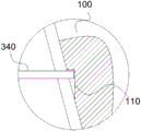
- Authority
- CN
- China
- Prior art keywords
- push rod
- rod
- groove
- adjusting
- sliding
- Prior art date
- Legal status (The legal status is an assumption and is not a legal conclusion. Google has not performed a legal analysis and makes no representation as to the accuracy of the status listed.)
- Active
Links
- 230000007423 decrease Effects 0.000 claims description 2
- 238000012423 maintenance Methods 0.000 description 13
- 238000010586 diagram Methods 0.000 description 4
- 238000000034 method Methods 0.000 description 4
- 230000000694 effects Effects 0.000 description 3
- 239000002184 metal Substances 0.000 description 2
- 229910052755 nonmetal Inorganic materials 0.000 description 2
- 230000007306 turnover Effects 0.000 description 2
- 238000005065 mining Methods 0.000 description 1
- 230000004048 modification Effects 0.000 description 1
- 238000012986 modification Methods 0.000 description 1
- 238000006467 substitution reaction Methods 0.000 description 1
Images




Landscapes
- Superstructure Of Vehicle (AREA)
Abstract
The utility model relates to a novel engine cover for an automobile, which comprises a cover body, an access cover and a locking and adjusting component; the hood body is hinged with the automobile, a groove is formed in the hood body, and a clamping groove is formed in the hood body and located in the groove; the access cover is embedded in the groove, the access cover is hinged with the hood body, and a fixed block is arranged on the access cover; the locking and adjusting assembly comprises a telescopic piece, a push rod, an elastic piece and an adjusting rod, the telescopic piece, the push rod and the fixed block are sequentially arranged along a linear direction, the telescopic piece is fixed on the automobile, the telescopic end of the telescopic piece is fixedly connected with one end of the push rod, the other end of the push rod points to a through hole in the fixed block, the push rod is perpendicular to the adjusting rod, the push rod is slidably connected with the adjusting rod along the length direction of the push rod, the moving path of the push rod covers the clamping groove, and a first position and a second position are arranged on the push rod along the direction of the push rod; the problem of when overhauing the engine, current engine bonnet exposes the space of engine limited, has to overhaul inconvenient is solved.
Description
Technical Field
The utility model relates to a mining equipment technical field especially relates to a novel engine cover.
Background
At present engine bonnet and automobile body are fixed connection, play the effect of protection to the engine through engine bonnet, for the convenience of maintenance and the maintenance work of engine, it has an apron to articulate on the current engine bonnet, makes the engine expose outside through the upset apron, is convenient for maintain and the going on of maintenance work.
However, when the cover plate is turned over and then overhauled, the exposed space of the engine is limited, and the problem of inconvenient overhaul exists.
SUMMERY OF THE UTILITY MODEL
In view of this, a need exists for a novel engine cover to solve the problem that the existing engine cover has limited space for exposing the engine and is inconvenient to overhaul when the engine is overhauled.
The utility model provides a novel engine cover for an automobile, which comprises a cover body, an access cover and a locking and adjusting component; the hood body is hinged with the automobile, a groove is formed in the hood body, and a clamping groove is formed in the hood body and located in the groove; the access cover is embedded in the groove and is hinged with the hood body, and a fixed block is arranged on the access cover; the locking and adjusting assembly comprises a telescopic part, a push rod, an elastic part and an adjusting rod, the telescopic part, the push rod and a fixed block are sequentially arranged along a straight line direction, the telescopic part is fixed on the automobile, the telescopic end of the telescopic part is fixedly connected with one end of the push rod, the other end of the push rod points to a through hole on the fixed block, the push rod and the adjusting rod are vertically arranged, the push rod is slidably connected with the adjusting rod along the length direction of the push rod, the moving path of the push rod covers the clamping groove, a first position and a second position are arranged on the push rod along the direction of the push rod, one end of the elastic part is connected with the push rod, the other end of the elastic part is connected with the adjusting rod so that the adjusting rod can move to the first position or the second position, when the adjusting rod moves to the first position, the adjusting rod is abutted against the clamping groove, the push rod and the through hole are arranged at intervals, when the adjusting rod moves to the second position, the adjusting rod is abutted to the clamping groove, and the push rod penetrates through the through hole.
Further, the groove is located two sides of the push rod are inclined planes, the distance between the inclined planes is along the direction of the push rod is sequentially reduced along the direction of the fixed block, the number of the clamping grooves is two, and the clamping grooves are oppositely arranged on the two inclined planes.
Furthermore, a first sliding groove and a second sliding groove are formed in the push rod, the first sliding groove is communicated with the second sliding groove, the extending directions of the first sliding groove and the second sliding groove are the same as the length direction of the push rod, the adjusting rod penetrates through the second sliding groove and is in sliding connection with the second sliding groove, a sliding rod is fixedly connected to the push rod, and the sliding rod is in sliding connection with the first sliding groove.
Furthermore, one end of the sliding rod is in threaded connection with the push rod, the sliding rod and the push rod are perpendicular to each other, and the sliding rod and the adjusting rod are perpendicular to each other.
Furthermore, one side of the first sliding groove of the push rod, which is close to the fixed block, is a first position, and one side of the first sliding groove of the push rod, which is far away from the fixed block, is a second position.
Further, the elastic component includes push pedal, sleeve and spring, the push pedal set up in it keeps away from to adjust the pole fixed block one side, the push pedal with push rod fixed connection, the muffjoint is located on the push rod, the sleeve with adjust pole fixed connection, the push pedal with via between the sleeve spring fixed connection.
Compared with the prior art, because the metal and nonmetal mine underground dump truck has a bad operating environment and the maintenance frequency of vehicles is higher relative to a road truck, aiming at the situation, the two-stage turnover function can be realized by arranging the hood body to be hinged with the vehicle and the access cover to be hinged with the hood body, particularly, when the engine is subjected to daily maintenance or small maintenance work, the work can be realized by turning over the access cover, when the engine needs to be overhauled or even replaced, the hood body is turned over, so that the whole engine of the vehicle is exposed outside, the work is convenient to carry out, a customer can select to open the access cover or the hood body according to actual requirements in the using process, the maintenance efficiency is effectively improved, the approach of the engine is effectively improved, and meanwhile, by arranging the locking adjusting component, through the matching of the adjusting rod and the clamping groove, make aircraft bonnet body and automobile body relatively fixed, through the cooperation between the through-hole of push rod and fixed block, make access cover and aircraft bonnet body relatively fixed to realize protecting automobile engine's function.
Drawings
Fig. 1 is a schematic structural diagram of an embodiment of a novel engine cover provided by the present invention;
fig. 2 is a schematic structural diagram of a locking adjustment assembly in an embodiment of a novel engine cover provided by the present invention;
fig. 3 is an enlarged schematic view of a portion a in fig. 2 of a novel engine cover provided by the present invention;
fig. 4 is an enlarged schematic view of a portion B in fig. 2 of a novel engine cover provided by the present invention;
fig. 5 is a schematic structural view of the push rod passing through the fixed block in the embodiment of the novel engine cover provided by the present invention;
fig. 6 is an enlarged schematic view of a portion C in fig. 5 of a novel engine cover provided by the present invention;
fig. 7 is a schematic structural view of a push rod in an embodiment of a novel engine cover provided by the present invention;
fig. 8 is a schematic structural diagram of an adjusting rod in an embodiment of the novel engine cover provided by the present invention;
fig. 9 is a schematic structural view of a fixing block in an embodiment of a novel engine cover provided by the present invention;
fig. 10 is a schematic view illustrating the operation of opening the access cover in the embodiment of the novel engine cover according to the present invention;
fig. 11 is a schematic diagram illustrating the operation of opening the hood body in the embodiment of the novel engine hood.
Detailed Description
The following detailed description of the preferred embodiments of the invention, which is to be read in connection with the accompanying drawings, forms a part of this application, and together with the embodiments of the invention, serve to explain the principles of the invention and not to limit its scope.
As shown in fig. 1-2, the novel engine hood of the present embodiment is used for an automobile, and includes a hood body 100, an access cover 200, and a locking adjustment assembly 300, where the locking adjustment assembly 300 is installed on the automobile, the hood body 100 is hinged to the automobile, and the access cover 200 is hinged to the automobile.
The aircraft bonnet body 100 in this embodiment is articulated with the car for cover the engine of car, play the effect of protection to the engine of car, when needs overhaul, can rotate aircraft bonnet body 100 round the car, make the car engine expose completely, the easy access, wherein, in the recess of seting up on the aircraft bonnet body 100, the access cover 200 of being convenient for is placed in the recess, and the draw-in groove 110 has been seted up to the last groove site that just is located of aircraft bonnet body 100.
As shown in fig. 2 and 4, the two sides of the groove located on the push rod 320 in this embodiment are both inclined surfaces, the distance between the two inclined surfaces decreases in sequence along the direction from the push rod 320 to the fixed block 210, the number of the two slots 110 is two, and the two slots 110 are oppositely disposed on the two inclined surfaces.
As shown in fig. 1, the access cover 200 in this embodiment is smaller than the hood body 100, the access cover 200 is embedded in the groove, the access cover 200 is disposed on the hood body 100, the access cover 200 is hinged to the hood body 100, and when only the engine is maintained, only the access cover 200 may be opened for use in maintaining the engine, wherein the access cover 200 is provided with a fixing block 210.
The locking adjusting assembly 300 in this embodiment is used for adjusting the relative positions of the hood body 100 and the access cover 200 and the automobile, and specifically, the following functions can be realized through the locking adjusting assembly 300, wherein the first function is that the hood body 100 is fixed with the automobile, the second function is that the access cover 200 is fixed with the hood body 100, the hood body 100 is fixed with the automobile, the access cover 200 can rotate around the hood body 100, the third function is that the hood body 100 can rotate around the automobile, and the detailed explanation is performed on the overall structure and the specific functions of the locking adjusting assembly 300 below.
As shown in fig. 2-3 and 9, the locking adjustment assembly 300 in this embodiment includes a telescopic member 310, a push rod 320, an elastic member 330 and an adjustment rod 340, the telescopic member 310, the push rod 320 and the fixed block 210 are sequentially arranged along a linear direction, the telescopic member 310 is fixed to the vehicle, a telescopic end of the telescopic member 310 is fixedly connected to one end of the push rod 320, the other end of the push rod 320 is arranged to point to a through hole 211 on the fixed block 210, the push rod 320 is arranged perpendicular to the adjustment rod 340, the push rod 320 is slidably connected to the adjustment rod 340 along a length direction thereof, a moving path of the push rod 320 covers the slot 110, as shown in fig. 2-3 and 5-6, the push rod 320 has a first position and a second position arranged along the direction thereof, one end of the elastic member 330 is connected to the push rod 320, and the other end of the elastic member 330 is connected to the adjustment rod 340 for the adjustment rod 340 to move to the first position or the second position, when the adjustment rod 340 moves to the first position, the adjusting rod 340 is abutted against the clamping groove 110, the push rod 320 is arranged at intervals with the through hole 211, when the adjusting rod 340 moves to the second position, the adjusting rod 340 is abutted against the clamping groove 110, and the push rod 320 penetrates through the through hole 211.
The telescopic member 310 in this embodiment may be an oil cylinder, an electric push rod 320, or an air cylinder, as long as the push rod 320 can be driven to reciprocate along the length direction thereof.
As shown in fig. 7-8, the push rod 320 in this embodiment is provided with a first sliding slot 321 and a second sliding slot 322, the first sliding slot 321 is communicated with the second sliding slot 322, the extending directions of the first sliding slot 321 and the second sliding slot 322 are the same as the length direction of the push rod 320, the adjusting rod 340 passes through the second sliding slot 322 and is slidably connected with the second sliding slot 322, the push rod 320 is fixedly connected with a sliding rod 341, and the sliding rod 341 is slidably connected with the first sliding slot 321.
Further, one end of the sliding rod 341 is connected with the push rod 320 by a screw thread, the sliding rod 341 and the push rod 320 are arranged perpendicular to each other, and the sliding rod 341 and the adjusting rod 340 are arranged perpendicular to each other.
Further, a side of the first sliding groove 321 of the push rod 320, which is close to the fixed block 210, is a first position, and a side of the first sliding groove 321 of the push rod 320, which is far from the fixed block 210, is a second position.
As shown in fig. 2-3, the elastic member 330 in this embodiment includes a push plate 331, a sleeve 332 and a spring 333, the push plate 331 is disposed on a side of the adjustment lever 340 away from the fixing block 210, the push plate 331 is fixedly connected to the push rod 320, the sleeve 332 is sleeved on the push rod 320, the sleeve 332 is fixedly connected to the adjustment lever 340, and the push plate 331 and the sleeve 332 are fixedly connected via the spring 333.
The working process is as follows: when the engine of the automobile is in routine maintenance or small overhaul work, the telescopic member 310 is opened to drive the push rod 320 to move along the length direction thereof until one end of the push rod 320 is separated from the through hole 211 of the fixing block 210, at this time, the access cover 200 can be pulled upwards, and the access cover 200 rotates around the engine cover body 100 to a certain angle to expose part of the engine, as shown in fig. 10, so as to facilitate the routine maintenance work, when the engine needs overhaul (the overhaul refers to large modification range of the engine), even when the engine is replaced, the telescopic member 310 is opened to drive the push rod 320 to move along the length direction thereof until the adjusting rod 340 is separated from the clamping groove 110, at this time, the engine cover body 100 can rotate around the automobile body until the whole engine of the automobile is exposed, as shown in fig. 10. The operation is convenient to carry out, in the normal operation process of the automobile, in order to realize the protection effect on the engine, the telescopic piece 310 is opened, the push rod 320 drives the adjusting rod 340 to move, the two ends of the push rod 320 are firstly clamped into the two clamping grooves 110 respectively, at this time, the hood body 100 is fixed relative to the automobile, the push rod 320 continues to move, the push plate 331 extrudes the spring 333, at this time, the push rod 320 continues to move relative to the adjusting rod 340 until the push rod 320 penetrates through the through hole 211 of the fixing block 210, and at this time, the access cover 200 is fixed relative to the hood body 100.
Compared with the prior art: because the operation environment of the metal and nonmetal mine underground dump truck is severe, the maintenance frequency of the vehicle is higher relative to a road truck, aiming at the situation, the hood body 100 is hinged with the vehicle, and the access cover 200 is hinged with the hood body 100, so that the function of two-stage turnover can be realized, specifically, when the daily maintenance or small maintenance work of the engine is carried out, the work can be realized by turning over the access cover 200, when the engine needs to be overhauled or even replaced, the hood body 100 is turned over, so that the whole engine of the vehicle is exposed outside, the work is convenient to carry out, a customer can select to open the access cover 200 or the hood body 100 according to the actual requirements in the use process, the maintenance efficiency is effectively improved, the approach of the engine is effectively improved, meanwhile, by arranging the locking adjusting component 300, through the matching of the adjusting rod 340 and the clamping groove 110, the hood body 100 and the automobile body are relatively fixed, and the access cover 200 and the hood body 100 are relatively fixed through the matching between the push rod 320 and the through hole 211 of the fixing block 210, so that the function of protecting the automobile engine is realized.
The above description is only for the preferred embodiment of the present invention, but the scope of the present invention is not limited thereto, and any changes or substitutions that can be easily conceived by those skilled in the art within the technical scope of the present invention should be covered by the present invention.
Claims (6)
1. A novel engine hood is used for an automobile and is characterized by comprising a hood body, an access cover and a locking adjusting assembly;
the hood body is hinged with the automobile, a groove is formed in the hood body, and a clamping groove is formed in the hood body and located in the groove;
the access cover is embedded in the groove and is hinged with the hood body, and a fixed block is arranged on the access cover;
the locking and adjusting assembly comprises a telescopic part, a push rod, an elastic part and an adjusting rod, the telescopic part, the push rod and a fixed block are sequentially arranged along a straight line direction, the telescopic part is fixed on the automobile, the telescopic end of the telescopic part is fixedly connected with one end of the push rod, the other end of the push rod points to a through hole on the fixed block, the push rod and the adjusting rod are vertically arranged, the push rod is slidably connected with the adjusting rod along the length direction of the push rod, the moving path of the push rod covers the clamping groove, a first position and a second position are arranged on the push rod along the direction of the push rod, one end of the elastic part is connected with the push rod, the other end of the elastic part is connected with the adjusting rod so that the adjusting rod can move to the first position or the second position, when the adjusting rod moves to the first position, the adjusting rod is abutted against the clamping groove, the push rod and the through hole are arranged at intervals, when the adjusting rod moves to the second position, the adjusting rod is abutted to the clamping groove, and the push rod penetrates through the through hole.
2. The novel engine hood according to claim 1, wherein the grooves are inclined planes on both sides of the push rod, the distance between the two inclined planes decreases in sequence along the direction from the push rod to the fixed block, the number of the clamping grooves is two, and the two clamping grooves are oppositely arranged on the two inclined planes.
3. The novel engine hood according to claim 1, wherein the push rod is provided with a first sliding groove and a second sliding groove, the first sliding groove is communicated with the second sliding groove, the extending directions of the first sliding groove and the second sliding groove are the same as the length direction of the push rod, the adjusting rod penetrates through the second sliding groove and is in sliding connection with the second sliding groove, the push rod is fixedly connected with a sliding rod, and the sliding rod is in sliding connection with the first sliding groove.
4. The novel engine cover according to claim 3, characterized in that one end of the sliding rod is in threaded connection with the push rod, the sliding rod and the push rod are arranged perpendicular to each other, and the sliding rod and the adjusting rod are arranged perpendicular to each other.
5. The novel engine cover according to claim 3, characterized in that the side of the first sliding groove of the push rod close to the fixed block is at a first position, and the side of the first sliding groove of the push rod far from the fixed block is at a second position.
6. The novel engine hood according to claim 1, wherein the elastic member comprises a push plate, a sleeve and a spring, the push plate is arranged on one side of the adjusting rod, which is far away from the fixing block, the push plate is fixedly connected with the push rod, the sleeve is sleeved on the push rod, the sleeve is fixedly connected with the adjusting rod, and the push plate is fixedly connected with the sleeve through the spring.
Priority Applications (1)
| Application Number | Priority Date | Filing Date | Title |
|---|---|---|---|
| CN202022716306.0U CN213921237U (en) | 2020-11-20 | 2020-11-20 | Novel engine cover |
Applications Claiming Priority (1)
| Application Number | Priority Date | Filing Date | Title |
|---|---|---|---|
| CN202022716306.0U CN213921237U (en) | 2020-11-20 | 2020-11-20 | Novel engine cover |
Publications (1)
| Publication Number | Publication Date |
|---|---|
| CN213921237U true CN213921237U (en) | 2021-08-10 |
Family
ID=77172239
Family Applications (1)
| Application Number | Title | Priority Date | Filing Date |
|---|---|---|---|
| CN202022716306.0U Active CN213921237U (en) | 2020-11-20 | 2020-11-20 | Novel engine cover |
Country Status (1)
| Country | Link |
|---|---|
| CN (1) | CN213921237U (en) |
-
2020
- 2020-11-20 CN CN202022716306.0U patent/CN213921237U/en active Active
Similar Documents
| Publication | Publication Date | Title |
|---|---|---|
| US11958144B2 (en) | Self-adjusting wire feeder mounting assembly | |
| CN107030434B (en) | Multi-vehicle type positioning device on line side switching mechanism and repair welding line skid | |
| ATE299064T1 (en) | WINDOW LOCKING MECHANISM FOR MOTORIZED TOOL | |
| CN109413908B (en) | Electrical control cabinet | |
| CN213921237U (en) | Novel engine cover | |
| US20050012344A1 (en) | Chassis fairing latch with integral handle | |
| CN208486708U (en) | The self-locking system of vehicle tail door | |
| CN111505585A (en) | Novel vehicle-mounted radar flip mechanism | |
| EP1857340B2 (en) | Mass transit vehicles, in particular an urban railcar, with a front bonnet | |
| DE202024100582U1 (en) | Opening and closing device for a motor vehicle | |
| DE102020108004A1 (en) | Primary coupling device, secondary coupling device, fifth wheel assembly and automatic coupling system | |
| DE10048706A1 (en) | Door module for a vehicle door | |
| CN209237319U (en) | A kind of positioning and locking device of cross moving track vehicle | |
| CN214886335U (en) | Hinge assembly structure of front cover plate | |
| CN220374458U (en) | Front anti-collision device of automobile | |
| EP0894663A2 (en) | Mounting arrangement of a lighting unit for vehicle | |
| EP4108839A1 (en) | Protective canopy, earth working machine and method for changing position of the protective canopy | |
| CN215860275U (en) | Door opener device of underground coal mine air door | |
| CN218907055U (en) | Lamp system and vehicle | |
| CN214776196U (en) | Tail door locking device | |
| CN221343515U (en) | Elevator door machine installation structure | |
| CN224027503U (en) | Engine cover hinge positioning tool | |
| EP4700529A1 (en) | Multi-mode actuation mechanism | |
| CN218856788U (en) | Be applied to narrow regional bolt mounting tool | |
| CN214607329U (en) | Quick dismounting mechanism for vehicle-mounted portable dual-purpose photoelectric observation equipment |
Legal Events
| Date | Code | Title | Description |
|---|---|---|---|
| GR01 | Patent grant | ||
| GR01 | Patent grant |