CN213924497U - Cutting device for photovoltaic glass - Google Patents
Cutting device for photovoltaic glass Download PDFInfo
- Publication number
- CN213924497U CN213924497U CN202021938845.2U CN202021938845U CN213924497U CN 213924497 U CN213924497 U CN 213924497U CN 202021938845 U CN202021938845 U CN 202021938845U CN 213924497 U CN213924497 U CN 213924497U
- Authority
- CN
- China
- Prior art keywords
- seat
- glass
- cutting
- clamping
- jacking
- Prior art date
- Legal status (The legal status is an assumption and is not a legal conclusion. Google has not performed a legal analysis and makes no representation as to the accuracy of the status listed.)
- Active
Links
- 239000011521 glass Substances 0.000 title claims abstract description 66
- 230000007246 mechanism Effects 0.000 claims abstract description 102
- 230000005540 biological transmission Effects 0.000 claims description 18
- 230000007306 turnover Effects 0.000 claims description 15
- 239000000463 material Substances 0.000 abstract description 14
- 239000005304 optical glass Substances 0.000 abstract description 10
- 230000009194 climbing Effects 0.000 abstract description 4
- 230000009471 action Effects 0.000 description 5
- 238000000034 method Methods 0.000 description 5
- 230000008569 process Effects 0.000 description 5
- XEEYBQQBJWHFJM-UHFFFAOYSA-N Iron Chemical compound [Fe] XEEYBQQBJWHFJM-UHFFFAOYSA-N 0.000 description 4
- 239000003638 chemical reducing agent Substances 0.000 description 3
- 238000010586 diagram Methods 0.000 description 3
- 230000006698 induction Effects 0.000 description 2
- 229910052742 iron Inorganic materials 0.000 description 2
- 239000000956 alloy Substances 0.000 description 1
- 229910045601 alloy Inorganic materials 0.000 description 1
- 238000005516 engineering process Methods 0.000 description 1
- 239000000835 fiber Substances 0.000 description 1
- 238000003384 imaging method Methods 0.000 description 1
- 239000000087 laser glass Substances 0.000 description 1
- 230000003287 optical effect Effects 0.000 description 1
- 239000010453 quartz Substances 0.000 description 1
- 230000005855 radiation Effects 0.000 description 1
- VYPSYNLAJGMNEJ-UHFFFAOYSA-N silicon dioxide Inorganic materials O=[Si]=O VYPSYNLAJGMNEJ-UHFFFAOYSA-N 0.000 description 1
Images


Landscapes
- Re-Forming, After-Treatment, Cutting And Transporting Of Glass Products (AREA)
Abstract
The utility model discloses a cutting device for photovoltaic glass, the utility model belongs to the technical field of glass-cutting machine, a cutting device for photovoltaic glass stacks the automatic material loading cutting that carries on of strip optical glass at the material board through the manual work, in order to avoid mechanical work to take place to interfere, feeding mechanism passes through the side and pushes away the subassembly, feeding mechanism and cutting mechanism constitute, feeding mechanism is the subdividing into climbing mechanism, fixture, tilting mechanism and side push away the subassembly, climbing mechanism, the cylinder is selected to fixture and tilting mechanism's executive component, pushing mechanism has decided the precision of glass-cutting volume, consequently, select to be driven by servo motor and lead screw, the edge of having heard clamping mechanism protection glass can not destroy because of the impact of cylinder.
Description
Technical Field
The utility model belongs to the technical field of the glass-cutting machine, concretely relates to cutting device for photovoltaic glass.
Background
The optical glass is a basic and important component of the photoelectric technology industry, and has wide application in the fields of aerospace, imaging equipment, optical instruments and the like. The optical glass in a broad sense means colored optical glass, laser glass, quartz optical glass, radiation-resistant glass, ultraviolet infrared optical glass, fiber optical glass, acousto-optic glass, magneto-optic glass and photochromic glass, and the optical glass in a narrow sense means colorless optical glass.
The cutting device in the prior art cuts products with the same size and specification, the cut products have different differences, and due to the fact that the stress of glass is different from that of iron materials, the processing quality of brittle and hard materials of the glass is difficult to guarantee, and the processing efficiency is low.
SUMMERY OF THE UTILITY MODEL
Utility model purpose: the utility model provides a photovoltaic is cutting device for glass has solved the above-mentioned problem that prior art exists.
The technical scheme is as follows: a photovoltaic glass cutting device comprises a rack, an operating platform arranged on the rack, a cutting mechanism arranged on the operating platform, and a feeding mechanism which is arranged on the operating platform and positioned on the side surface of the cutting mechanism and used for feeding glass in place;
the cutting mechanism comprises a transmission seat arranged on the operating platform, two groups of linear slide rails arranged on the transmission seat, a sliding bottom plate arranged on the linear slide rails, a cutting motor arranged on the sliding bottom plate, a grinding wheel arranged on the cutting motor, a servo motor arranged on the transmission seat and positioned in the transmission seat, and a ball screw connected with the servo motor;
the feeding mechanism comprises a supporting seat fixedly mounted on the operating platform, a jacking mechanism arranged on the supporting seat, a clamping mechanism connected with the jacking mechanism, a turnover mechanism connected with the clamping mechanism, and a side pushing assembly connected with the turnover mechanism.
In a further embodiment, the jacking mechanism comprises a jacking base arranged on the supporting base, a sliding rail arranged on the jacking base, a cylinder seat connected with the jacking base, a jacking cylinder arranged on the cylinder seat, a connecting plate arranged on the sliding rail, and a jacking block screwed on the connecting plate.
In a further embodiment, the cylinder shaft of the jacking cylinder is connected with the connecting plate.
In a further embodiment, the top piece is designed to be detachable.
In a further embodiment, the clamping mechanism comprises two sliding seats, a clamping seat arranged on the sliding seats, a clamping cylinder arranged on the clamping seat, a connecting rod with two ends arranged on the clamping seat, and a clamping jaw arranged on the clamping seat.
In a further embodiment, the angle between the clamping jaw and the clamping seat is set to be 75-90 degrees.
Has the advantages that: the utility model provides a cutting device for photovoltaic glass, stack the automatic material loading cutting that carries out at the strip optical glass of material board through the manual work, avoid mechanical work to take place to interfere, feeding mechanism pushes away the subassembly through the side, feeding mechanism and cutting mechanism constitute, feeding mechanism subdivides into climbing mechanism, fixture, tilting mechanism and side push away the subassembly, climbing mechanism, the cylinder is selected to the executor of fixture and tilting mechanism, pushing mechanism has decided the precision of glass-cutting volume, consequently, select to be driven by servo motor and lead screw, the edge of having heard clamping mechanism protection glass can not destroy because of the impact of cylinder. The cutting mechanism feeds under the control of the servo motor, in the feeding process, the sensing contact and the cutter are simultaneously contacted with the glass, in order to ensure the smoothness of the section of the glass, the radial direction of the cutter is ensured to be vertical to the cut surface of the glass as far as possible in the assembly process, when the glass is cut off, the sensing contact resets under the action of the spring and simultaneously sends a signal to the control system, so that the servo motor rotates reversely to drive the sliding bottom plate to move reversely to retract the cutter. In order to avoid that the rotation speed of the servo motor is too high, so that the inertia of the system is too large and the mechanism is vibrated too strongly, the servo motor and the lead screw are selected to be connected. The cutting efficiency and the safety are improved.
Drawings
Fig. 1 is a front view of the present invention.
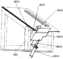
Fig. 2 is a schematic structural diagram of the jacking mechanism of the present invention.
Fig. 3 is a schematic structural diagram of the clamping mechanism of the present invention.
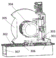
Fig. 4 is a schematic structural diagram of the cutting mechanism of the present invention.
The various reference numbers in the figures are labeled; the cutting machine comprises a machine frame 1, an operating platform 2, a cutting mechanism 3, a transmission seat 301, a linear slide rail 302, a sliding bottom plate 303, a cutting motor 304, a grinding wheel 305, a servo motor 306, a ball screw 307, a feeding mechanism 4, a supporting seat 401, a jacking mechanism 402, a jacking base 4021, a first slide rail 4022, a cylinder seat 4023, a jacking cylinder 4024, a connecting plate 4025, a jacking block 4026, a clamping mechanism 403, a slide seat 4031, a clamping seat 4032, a clamping cylinder 4033, a connecting rod 4034, a clamping jaw 4035, a turnover mechanism 404 and a side pushing assembly 405.
Detailed Description
Through research and analysis of the applicant, the cutting device in the prior art cuts products with the same size and specification, different differences exist between the cut products, the processing quality of the brittle and hard material of the glass is difficult to guarantee due to different stresses between the glass and the iron material, and the processing efficiency is low.
The cutting device for the photovoltaic glass comprises a rack 1, a cutting mechanism 3 and a feeding mechanism 4, wherein the rack 1 is arranged at a designated position, the operating platform is arranged on the rack 1, the cutting mechanism 3 is arranged on the operating platform 2, and the feeding mechanism 4 is arranged on the operating platform 2 and is positioned on the side surface of the cutting mechanism 3.
The cutting mechanism 3 includes a transmission base 301, a linear slide rail 302, a slide base 303, a cutting motor 304, a grinding wheel 305, a servo motor 306, and a ball screw 307, wherein the transmission base 301 is disposed on the operation platform 2, the linear slide rail 302 is disposed on the transmission base 301, the slide base 303 is disposed on the linear slide rail 302, the cutting motor 304 is disposed on the slide base 303, the grinding wheel 305 is disposed on the cutting motor 304, the servo motor 306 is disposed on the transmission base 301 and located inside the transmission base 301, and the ball screw 307 is connected with the servo motor 306. The core of the cutting mechanism 3 is a hard alloy cutter driven by a servo motor 306 to rotate at a high speed, in order to realize the feeding and retracting of the grinding wheel 305, the cutting motor 304 is connected onto the transmission seat 301 through a sliding bottom plate 303, the power element of the transmission seat 301 is the servo motor 306, the servo motor is connected with a ball screw through a speed reducer for transmission, so that the grinding wheel 305 can move in the horizontal direction along the direction of a sliding rail on the transmission seat 301, the glass is pushed through a guide rail by a material pushing mechanism, when the cutting is judged to be carried out by image processing software, the cutting mechanism 3 feeds under the control of the servo motor 306, in the feeding process, an induction contact and the cutter are simultaneously contacted with the glass, in order to ensure the smoothness of the section of the glass, the radial direction of the cutter is ensured to be vertical to the cut surface of the glass as much as possible in the assembly, and when the glass is cut, the induction contact is reset under the action of a spring, meanwhile, a signal is sent to the control system, so that the servo motor 306 is reversely rotated to drive the sliding bottom plate 303 to reversely move, and the cutter is withdrawn. In order to avoid that the rotation speed of the servo motor 306 is too high, so that the inertia of the system is too large, and too strong vibration is caused to the mechanism, a speed reducer is selected to connect the servo motor 306 and the wire.
The feeding mechanism 4 comprises a supporting seat 401, a jacking mechanism 402, a jacking base 4021, a first sliding rail 4022, a cylinder seat 4023, a jacking cylinder 4024, a connecting plate 4025, a jacking block 4026, a clamping mechanism 403, a sliding seat 4031, a clamping seat 4032, a clamping cylinder 4033, a connecting rod 4034, a clamping jaw 4035, a turnover mechanism 404 and a side pushing assembly 405; the supporting seat 401 is fixedly installed on the operating platform 2, the jacking mechanism 402 is arranged on the supporting seat 401, the clamping mechanism 403 is connected with the jacking mechanism 402, the turnover mechanism 404 is connected with the clamping mechanism 403, the side pushing assembly 405 is connected with the turnover mechanism 404, the ejecting base 4021 is arranged on the supporting seat 401, the first sliding rail 4022 is arranged on the ejecting base 4021, the cylinder seat 4023 is connected with the ejecting base 4021, the jacking cylinder 4024 is arranged on the cylinder seat 4023, the connecting plate 4025 is arranged on the first sliding rail 4022, and the cylinder shaft of the jacking cylinder 4024 is connected with the connecting plate 4025. The top block 4026 is screwed on the connecting plate 4025 above the connecting plate 4025, and the top block 4026 is designed to be detachable. The sliding seat 4031 is arranged on the upper surface of the operating platform 2, the clamping seat 4032 is arranged on the upper surface of the sliding seat 4031, the clamping cylinder 4033 is arranged on the upper surface of the clamping seat 4032, two ends of the connecting rod 4034 are arranged on the upper surface of the clamping seat 4032, the clamping jaw 4035 is arranged on the upper surface of the clamping seat 4032, and the angle between the clamping jaw 4035 and the clamping seat 4032 is set to be 75-90 degrees.
Specifically, the feeding mechanism 4 mainly comprises a jacking mechanism 402, a clamping mechanism 403, a turnover mechanism 404 and a side pushing mechanism, the working sequence of the feeding mechanism is that the jacking mechanism 402 jacks up strip-shaped glass on a material plate, so that the clamping mechanism 403 clamps the glass, after the clamping mechanism 403 clamps the glass, the turnover mechanism 404 overturns to adjust the posture of the glass, then the side pushing mechanism places the glass on a track, the pushing and cutting are completed, the glass stacked on the material plate is sequentially clamped and then cut, and the glass next to the material plate is firstly separated. The jacking mechanism 402 takes an air cylinder as an executive component, the glass is jacked up through a sliding rail and the jacking block 4026, then the glass is clamped by the clamping mechanism 403, the air cylinder contracts, and the glass on the material plate slides down above the jacking block 4026 again under the action of self weight to wait for jacking next time.
Meanwhile, the cross sections of the glass are different in size, and the top block 4026 is detachable, so that the specification serialization of the top block 4026 is met to adapt to the glass with different specifications.
As a preferable scheme, the clamping mechanism 403 has the function of clamping the glass jacked up by the jacking mechanism 402, then the glass strip is sent to the material pushing track for cutting under the action of the turnover mechanism 404 and the side pushing mechanism, when the jacked-up glass is placed between the clamping seat 4032 and the clamping jaw 4035, the clamping cylinder 4033 is electrically extended under the control of the control system, so that the sliding seat 4031 and the clamping jaw 4035 tend to be closed, and the glass is clamped; the clamping seat 4032 is connected with the sliding seat 4031 through a dovetail groove, so that the angle between the sliding seat 4031 and the clamping jaw 4035 can be kept at 90 degrees all the time without changing, and the edge of glass can be protected from being damaged due to the impact of an air cylinder.
Specifically, in order to facilitate the glass strip to slide under its own weight above the ejector mechanism for automatic feeding, the glass is not horizontal after being gripped by the gripper 403; therefore, the glass needs to be turned over at a certain angle before being placed on the track, so that the bottom surface of the glass is in a horizontal position, the power of the turning mechanism 404 is provided by a turning cylinder, the turning cylinder is fixed on the hinge plate through a turning cylinder seat 4023, the turning connecting rod is in interference connection with the connecting rod, and the turning connecting rod and the connecting rod cannot rotate relatively through a jacking screw; the two ends of the connecting rod are connected with the clamping mechanism 403 through the connecting plate 4025, two ends of the connecting rod are respectively provided with a 3 x 3 key slot, and the connecting rod is connected with the connecting plate 4025 through a key, so that the turnover mechanism 404 can rotate along with the connecting rod. After the clamping mechanism 403 clamps the glass strip, the electromagnetic valve of the turnover cylinder is powered on under the control of the control system, and the turnover cylinder extends out, so that the turnover connecting rod rotates around the connecting rod, and meanwhile, the connecting rod rotates synchronously, so that the clamping mechanism 403 clamping the glass rotates, and the glass rotates to the required posture.
The side pushing assembly 405 is composed of a side pushing cylinder and a connecting plate 4025, and the main function of the side pushing assembly 405 is to stably push the glass, which is overturned to be horizontal by the overturning mechanism 404, to the guide rail from the side along the direction of the side pushing guide rail seat and the guide rail to prepare for pushing
As a preferable scheme, the glass is pushed through the guide rail by the side pushing assembly 405, when the image processing software judges that cutting is to be performed, the cutting mechanism 3 feeds under the control of the servo motor 306, in the feeding process, the sensing contact and the cutter simultaneously contact the glass, in order to ensure the smoothness of the glass section, the radial direction of the cutter is ensured to be vertical to the cut surface of the glass as much as possible in the assembly process, when the glass is cut off, the sensing contact resets under the action of the spring, and simultaneously sends a signal to the control system, so that the servo motor 306 is reversed to drive the sliding bottom plate 303 to move reversely to retract the cutter. In order to avoid that the rotation speed of the servo motor 306 is too high, so that the inertia of the system is too large, and too strong vibration is caused to the mechanism, a speed reducer is selected to connect the servo motor 306 and the lead screw.
It should be noted that the various features described in the above embodiments may be combined in any suitable manner without departing from the scope of the invention. The invention is not described in detail in order to avoid unnecessary repetition.
Claims (6)
1. The photovoltaic glass cutting device is characterized by comprising a rack, an operating platform arranged on the rack, a cutting mechanism arranged on the operating platform, and a feeding mechanism which is arranged on the operating platform and positioned on the side surface of the cutting mechanism and used for feeding glass in place;
the cutting mechanism comprises a transmission seat arranged on the operating platform, two groups of linear slide rails arranged on the transmission seat, a sliding bottom plate arranged on the linear slide rails, a cutting motor arranged on the sliding bottom plate, a grinding wheel arranged on the cutting motor, a servo motor arranged on the transmission seat and positioned in the transmission seat, and a ball screw connected with the servo motor;
the feeding mechanism comprises a supporting seat fixedly mounted on the operating platform, a jacking mechanism arranged on the supporting seat, a clamping mechanism connected with the jacking mechanism, a turnover mechanism connected with the clamping mechanism, and a side pushing assembly connected with the turnover mechanism.
2. The cutting device for photovoltaic glass according to claim 1, characterized in that: the jacking mechanism comprises a jacking base arranged on the supporting base, a first sliding rail arranged on the jacking base, a cylinder seat connected with the jacking base, a jacking cylinder arranged on the cylinder seat, a connecting plate arranged on the first sliding rail, and a jacking block screwed on the connecting plate.
3. The cutting device for photovoltaic glass according to claim 2, characterized in that: and a cylinder shaft of the jacking cylinder is connected with the connecting plate.
4. The cutting device for photovoltaic glass according to claim 2, characterized in that: the top block is designed to be detachable.
5. The cutting device for photovoltaic glass according to claim 1, characterized in that: the clamping mechanism comprises two sliding seats, a clamping seat arranged on the sliding seats, a clamping cylinder arranged on the clamping seat, a connecting rod with two ends arranged on the clamping seat, and a clamping jaw arranged on the clamping seat.
6. The cutting device for photovoltaic glass according to claim 5, characterized in that: the angle between the clamping jaw and the clamping seat is set to be 75-90 degrees.
Priority Applications (1)
| Application Number | Priority Date | Filing Date | Title |
|---|---|---|---|
| CN202021938845.2U CN213924497U (en) | 2020-09-08 | 2020-09-08 | Cutting device for photovoltaic glass |
Applications Claiming Priority (1)
| Application Number | Priority Date | Filing Date | Title |
|---|---|---|---|
| CN202021938845.2U CN213924497U (en) | 2020-09-08 | 2020-09-08 | Cutting device for photovoltaic glass |
Publications (1)
| Publication Number | Publication Date |
|---|---|
| CN213924497U true CN213924497U (en) | 2021-08-10 |
Family
ID=77160504
Family Applications (1)
| Application Number | Title | Priority Date | Filing Date |
|---|---|---|---|
| CN202021938845.2U Active CN213924497U (en) | 2020-09-08 | 2020-09-08 | Cutting device for photovoltaic glass |
Country Status (1)
| Country | Link |
|---|---|
| CN (1) | CN213924497U (en) |
-
2020
- 2020-09-08 CN CN202021938845.2U patent/CN213924497U/en active Active
Similar Documents
| Publication | Publication Date | Title |
|---|---|---|
| EP3318363B1 (en) | Laser processing machine, laser processing method, board material processing system, and board material processing method | |
| CN207139496U (en) | A kind of polishing work station applied to 3C industries | |
| US4796341A (en) | Plate routing method and apparatus | |
| CN110370401B (en) | A conical round material automatic fixed-length sawing and sorting device | |
| CN114454367A (en) | Silicon rod cutting method, equipment and system | |
| CN209698349U (en) | Efficient welding equipment | |
| CN118705962B (en) | A wheel hub thread inspection device | |
| CN117299872A (en) | A multi-model guide rail roller straightening equipment | |
| CN113096916B (en) | Welding magnetizing equipment | |
| CN112652804B (en) | Automatic flanging, sealing and channeling production line for batteries | |
| CN117381190A (en) | A three-dimensional five-axis profile laser cutting machine | |
| CN212707462U (en) | Single silicon rod diamond wire squarer | |
| CN213924497U (en) | Cutting device for photovoltaic glass | |
| CN111590770A (en) | Single silicon rod diamond wire squarer | |
| CN116277557A (en) | A silicon rod clamping and cutting method | |
| CN213005968U (en) | A square-cut machine based on double-sided floating clamping | |
| CN108515581B (en) | Solid wood cutting machine | |
| CN111300166B (en) | Steel ring surface polishing equipment and polishing method | |
| CN218696741U (en) | Feeding mechanism and grinding device | |
| CN113118522A (en) | Automatic centre milling and printing equipment | |
| CN116833775A (en) | Cutting device for steel plate blanking | |
| CN114734273B (en) | High-precision numerical control cutting equipment based on sensor | |
| CN116277558A (en) | Silicon rod squaring cutting device | |
| CN209424608U (en) | One kind being used for the inside and outside cutting edge of pliers and the automation integrated machining tool of square opening | |
| JP2002283136A (en) | Method and device for cutting workpiece |
Legal Events
| Date | Code | Title | Description |
|---|---|---|---|
| GR01 | Patent grant | ||
| GR01 | Patent grant | ||
| TR01 | Transfer of patent right | ||
| TR01 | Transfer of patent right |
Effective date of registration: 20230423 Address after: No. 3-27, Lingcheng Industrial Concentration Zone, Suining County, Xuzhou City, Jiangsu Province, 221000 Patentee after: Jiangsu Wushuang New Energy Technology Co.,Ltd. Address before: 213000 Room 302, No. 888, Changcheng Road, Xinbei District, Changzhou City, Jiangsu Province Patentee before: Changzhou Rongke New Material Co.,Ltd. |