CN213929368U - Planetary gear reducer of high-efficient operation - Google Patents
Planetary gear reducer of high-efficient operation Download PDFInfo
- Publication number
- CN213929368U CN213929368U CN202022338112.1U CN202022338112U CN213929368U CN 213929368 U CN213929368 U CN 213929368U CN 202022338112 U CN202022338112 U CN 202022338112U CN 213929368 U CN213929368 U CN 213929368U
- Authority
- CN
- China
- Prior art keywords
- planetary gear
- worm
- threaded rod
- output shaft
- gear reducer
- Prior art date
- Legal status (The legal status is an assumption and is not a legal conclusion. Google has not performed a legal analysis and makes no representation as to the accuracy of the status listed.)
- Expired - Fee Related
Links
Images


Landscapes
- Retarders (AREA)
- Connection Of Motors, Electrical Generators, Mechanical Devices, And The Like (AREA)
Abstract
The utility model discloses a planetary gear reducer with high-efficiency operation, which structurally comprises a bottom plate, a fixed plate, a cylinder body, a mounting plate, a protective cover and an output shaft, the auxiliary adjusting device is arranged at the front end of the top of the bottom plate, the driving mechanism drives the threaded rod to rotate, the sliding block slides on the outer surface of the threaded rod through the internal thread, the sliding block slides upwards on the inner side surface of the sliding groove, the sliding block drives the inner cylinder to move upwards, the inner cylinder adjusts the position of the output shaft through the top plate, and the effect of auxiliary adjustment of the output shaft is achieved, through having set up actuating mechanism at the inside lower extreme of urceolus, resume worm turned state through the retaining member, clockwise rotation hand wheel, the hand wheel drives the worm and rotates, and the worm drives the worm wheel and rotates, and the worm wheel drives the threaded rod and rotates, reaches the effect of drive threaded rod, this device convenient to use easy operation, the effectual work efficiency that has improved.
Description
Technical Field
The utility model relates to a planetary gear speed reducer technical field, concretely relates to planetary gear speed reducer of high-efficient operation.
Background
In a speed reducer family, the planetary speed reducer is widely applied to transmission systems such as servo motors, stepping motors, direct current motors and the like due to the advantages of small size, high transmission efficiency, wide speed reduction range, high precision and the like, and has the function of needing to use the planetary speed reducer which runs efficiently in the process of reducing the rotating speed, increasing the torque and reducing the rotational inertia ratio of the load/the motor on the premise of ensuring the precision transmission.
However, the planetary gear reducer which operates efficiently generally drives the sun gear to rotate through the motor, the sun gear drives the planetary gear to rotate, the planetary gear and the outer gear ring rotate in an engaged mode, the speed is reduced by increasing the torque and reducing the rotational inertia ratio of the load/the motor, however, the traditional rotational speed increasing torque and reducing the rotational inertia ratio of the load/the motor are poor in adjusting effect on the output shaft, the output shaft is prone to deviation in the using process, the reducing effect is reduced, and meanwhile, the traditional planetary gear reducer which operates efficiently is poor in driving effect on the threaded rod, and the use is inconvenient.
SUMMERY OF THE UTILITY MODEL
Technical problem to be solved
In order to overcome the defects of the prior art, the planetary gear speed reducer capable of efficiently running is provided, and the problems that the adjusting effect of the traditional rotating speed increasing torque and the rotating inertia ratio of the load/motor is poor to the output shaft, the output shaft is easy to deviate in the using process, the speed reducing effect is reduced, and meanwhile, the driving effect of the traditional planetary gear speed reducer capable of efficiently running is poor to a threaded rod, and the use is inconvenient are solved.
(II) technical scheme
The utility model discloses a following technical scheme realizes: the utility model provides a planetary gear reducer with high-efficiency operation, which comprises a bottom plate,
the auxiliary adjusting device is used for carrying out auxiliary adjustment on the output shaft;
the fixing plate is used for fixedly mounting the cylinder;
the cylinder is used for positioning and mounting the motor;
the planetary gear is used for achieving a speed reduction effect;
the motor is used for driving the sun wheel to drive;
the sun gear is used for driving the planetary gear to move;
the cylinder body is cylindrical, and a layer of waterproof and anti-oxidation layer is bonded on the outer surface of the cylinder body;
the diameter of the planet gears is set to be six centimeters, and the number of the planet gears is three.
The utility model discloses a motor, including bottom plate, barrel, mounting panel, protection casing, bottom plate top, bottom plate, output shaft, sun gear, motor output end, the fixed plate is fixed with to bottom plate top rear end, the barrel is installed to the terminal surface before the fixed plate, the terminal surface is fixed with the mounting panel before the barrel, the terminal surface is provided with the protection casing before the mounting panel, the protection casing middle part runs through there is the output shaft, bottom plate top front end is provided with supplementary adjusting device, the inside front end of barrel is provided with outer ring gear, planetary gear is installed to the inside front end equidistance of barrel to planetary gear and outer ring gear surface intermeshing, barrel internally mounted has the motor, output shaft surface middle part is provided with the sun gear to sun gear and planetary gear surface intermeshing, the output shaft rotates with motor output end to be connected.
The auxiliary adjusting device comprises a connecting plate, an outer barrel, an actuating mechanism, an inner barrel, a top plate, a sliding groove, a sliding block and a threaded rod, wherein the outer barrel is fixed at the middle part of the top end of the connecting plate, the actuating mechanism is arranged at the lower end of the inner barrel, the inner barrel is movably connected with the upper end of the inner barrel, the top plate is fixedly connected with the top of the inner barrel, the sliding groove is embedded into the upper end of the inner barrel, the sliding block is slidably connected with the inner side surface of the sliding groove, the threaded rod penetrates through the middle part of the sliding block, and the connecting plate is fixedly connected with the front end of the top of the bottom plate.
The driving mechanism comprises a worm wheel, a worm, a hand wheel and a locking piece, the worm is arranged on the front end face of the worm wheel, the worm is meshed with the outer surface of the worm wheel, the hand wheel is fixedly connected with the right end of the worm, the locking piece is installed at the right end of the outer surface of the worm, and the threaded rod penetrates through the middle of the worm wheel.
The inner middle part of the sliding block is provided with internal threads, and the sliding block is in threaded connection with the outer surface of the threaded rod.
The length of the sliding groove is set to be 10 cm, and the inner side surface of the sliding groove is a smooth plane.
The diameter of the hand wheel is set to six centimeters, and a layer of anti-skid grains is arranged on the outer surface of the sliding groove.
The retaining member is the cuboid form to the retaining member passes through bolt and urceolus right side lower extreme fixed connection.
The outer cylinder is made of carbon steel.
The cylinder is made of stainless steel.
(III) advantageous effects
Compared with the prior art, the utility model, following beneficial effect has:
1) the inertia ratio for solving traditional rotational speed increase moment of torsion and reducing load/motor is to the relatively poor problem of output shaft regulating effect, through having set up supplementary adjusting device at bottom plate top front end, drive the threaded rod through actuating mechanism and rotate, make the slider slide at the threaded rod surface through the internal thread, the slider is upwards slided at the spout medial surface simultaneously, the slider drives the inner tube rebound, the inner tube passes through the roof and adjusts the output shaft position, reach the effect of supplementary regulation output shaft.
2) For the relatively poor problem of solving the traditional high-efficient planetary gear reducer who moves to the threaded rod drive effect, through having set up actuating mechanism at the inside lower extreme of outer section of thick bamboo, resume worm turned state through the retaining member, clockwise rotation hand wheel, the hand wheel drives the worm and rotates, worm and worm wheel surface intermeshing, the worm drives the worm wheel and rotates, and the worm wheel drives the threaded rod and rotates, reaches the effect of drive threaded rod.
Drawings
Other features, objects and advantages of the invention will become more apparent upon reading of the detailed description of non-limiting embodiments with reference to the following drawings:
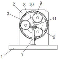
fig. 1 is a schematic structural view of the present invention;
FIG. 2 is a schematic front sectional view of the present invention;
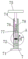
FIG. 3 is a schematic structural view of an auxiliary adjusting device of the present invention;
FIG. 4 is a schematic front sectional view of the auxiliary adjusting device of the present invention;
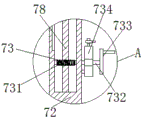
fig. 5 is a front sectional structural schematic view of the driving mechanism of the present invention.
In the figure: the device comprises a bottom plate-1, a fixing plate-2, a cylinder-3, a mounting plate-4, a protective cover-5, an output shaft-6, an auxiliary adjusting device-7, an outer gear ring-8, a planetary gear-9, a motor-10, a sun gear-11, a connecting plate-71, an outer cylinder-72, a driving mechanism-73, an inner cylinder-74, a top plate-75, a chute-76, a sliding block-77, a threaded rod-78, a worm wheel-731, a worm-732, a hand wheel-733 and a locking piece-734.
Detailed Description
In order to make the objects, technical solutions and advantages of the present invention more clearly understood, the present invention is further described in detail below with reference to the accompanying drawings and embodiments. It should be understood that the specific embodiments described herein are merely illustrative of the invention and are not intended to limit the invention.
Referring to fig. 1, 2, 3, 4 and 5, the present invention provides a planetary gear reducer with high efficiency: comprises a bottom plate 1 and a plurality of supporting plates,
an auxiliary adjusting device 7 for performing auxiliary adjustment on the output shaft 6;
the fixing plate 2 is used for fixedly mounting the cylinder 3;
the cylinder 3 is used for positioning and mounting the motor 10;
the planetary gear 9 is used for achieving a speed reduction effect;
the motor 10 is used for driving the sun gear 11 to drive;
the sun gear 11 is used for driving the planet gear 9 to move;
the cylinder 3 is cylindrical, and a layer of waterproof and anti-oxidation layer is bonded on the outer surface of the cylinder 3;
the planetary gears 9 are arranged to have a diameter of six centimeters, and the planetary gears 9 are arranged in three in total.
1 top rear end of bottom plate is fixed with fixed plate 2, barrel 3 is installed to 2 preceding terminal surface upper ends of fixed plate, the terminal surface is fixed with mounting panel 4 before barrel 3, the terminal surface is provided with protection casing 5 before mounting panel 4, 5 middle parts of protection casing run through there is output shaft 6, 1 top front end of bottom plate is provided with supplementary adjusting device 7, 3 inside front ends of barrel are provided with outer ring gear 8, planetary gear 9 is installed to 3 inside front end equidistance of barrel to planetary gear 9 and 8 surface intermeshing of outer ring gear, 3 internally mounted of barrel have motor 10, 6 surface middle parts of output shaft are provided with sun gear 11 to sun gear 11 and planetary gear 9 surface intermeshing, output shaft 6 rotates with the motor 10 output and is connected.
The driving mechanism 73 comprises a worm wheel 731, a worm 732, a hand wheel 733 and a locking piece 734, the worm 732 is arranged on the front end face of the worm wheel 731, the worm 732 is meshed with the outer surface of the worm wheel 731, so that the worm 732 can be fixed and installed conveniently, the hand wheel 733 is fixedly connected with the right end of the worm 732 and is favorable for fixing and installing the hand wheel 733, the locking piece 734 is installed at the right end of the outer surface of the worm 732, so that the locking piece 734 can be fixed and installed conveniently, and the threaded rod 78 penetrates through the middle part of the worm wheel 731.
The inner middle part of the sliding block 77 is provided with internal threads, and the sliding block 77 is in threaded connection with the outer surface of the threaded rod 78, so that the sliding block 77 can better slide on the outer surface of the threaded rod 78.
The length of the sliding groove 76 is set to be 10 cm, and the inner side surface of the sliding groove 76 is a smooth plane, so that the sliding block 77 can better slide on the inner side surface of the sliding groove 76.
The diameter of the hand wheel 733 is set to six centimeters, and a layer of anti-skid lines is arranged on the outer surface of the sliding groove 76, so that the situation that hands slide in the using process is prevented.
The locking member 734 is rectangular and the locking member 734 is fixedly connected to the lower right end of the outer cylinder 72 through a bolt, so as to achieve a better effect of locking the worm 732.
The outer cylinder 72 is made of carbon steel and has the advantages of light weight and high hardness.
The cylinder 3 is made of stainless steel and has the advantage of longer service life.
The sun gear 11 described in this patent is a basic component of the epicyclic gear train, in the planetary gear train, the external gear as the central gear is called the sun gear, the sun gear shaft is directly connected with the high-speed shaft by using single-tooth or double-tooth gear coupling, and no additional support is added, so that the floating of the sun gear is realized, and the purpose of uniform load is achieved.
The utility model discloses a planetary gear reducer of high-efficient operation, its theory of operation as follows:
firstly, moving the device to a place to be used, sequentially installing a planetary gear 9, a motor 10 and a sun gear 11 in a cylinder 3, so that the planetary gear 9 is meshed with the outer surface of an outer gear ring 8, and the sun gear 11 is meshed with the outer surface of the planetary gear 9;
secondly, when the motor 10 is started through an external control switch, the motor 10 drives the sun gear 11 to rotate through the output end, the sun gear 11 drives the planet gear 9 to rotate, so that the planet gear 9 and the external gear ring 8 are meshed with each other to rotate, and the speed is reduced by increasing the torque at a rotating speed and reducing the rotational inertia ratio of a load to the motor;
thirdly, when the output shaft 6 needs to be adjusted, the rotation state of the worm 732 is restored through the locking piece 734, the hand wheel 733 is rotated clockwise, the hand wheel 733 drives the worm 732 to rotate, the worm 732 is meshed with the outer surface of the worm wheel 731, the worm 732 drives the worm wheel 731 to rotate, and the worm wheel 731 drives the threaded rod 78 to rotate;
fourthly, the threaded rod 78 rotates, so that the sliding block 77 slides on the outer surface of the threaded rod 78 through the internal threads, the sliding block 77 slides upwards on the inner side surface of the sliding groove 76, the sliding block 77 drives the inner cylinder 74 to move upwards, the inner cylinder 74 adjusts the position of the output shaft 6 through the top plate 75, and the effect of assisting in adjusting the output shaft 6 is achieved;
fifthly, after the device is used, the motor 10 is turned off through the external control switch, the hand wheel 733 is rotated anticlockwise, the hand wheel 733 drives the worm wheel 731 to rotate through the worm 732, the worm wheel 731 drives the threaded rod 78 to rotate, the sliding block 77 moves downwards on the inner side face of the sliding groove 76, the sliding block 77 drives the top plate 75 to move downwards through the inner cylinder 74, the top plate 75 is separated from the outer surface of the output shaft 6, and finally the worm 732 is locked through the locking piece 734.
The basic principles and the main features of the invention and the advantages of the invention have been shown and described above, it will be evident to those skilled in the art that the invention is not limited to the details of the foregoing illustrative embodiments, but that the invention may be embodied in other specific forms without departing from the spirit or essential characteristics of the invention. The present embodiments are therefore to be considered in all respects as illustrative and not restrictive, the scope of the invention being indicated by the appended claims rather than by the foregoing description, and all changes which come within the meaning and range of equivalency of the claims are therefore intended to be embraced therein. Any reference sign in a claim should not be construed as limiting the claim concerned.
Furthermore, it should be understood that although the present description refers to embodiments, not every embodiment may contain only a single embodiment, and such description is for clarity only, and those skilled in the art should integrate the description, and the embodiments may be combined as appropriate to form other embodiments understood by those skilled in the art.
Claims (8)
1. The utility model provides a planetary gear reducer of high-efficient operation, includes bottom plate (1), its characterized in that still includes:
an auxiliary adjustment device (7) for auxiliary adjustment of the output shaft (6);
the fixing plate (2) is used for fixedly mounting the cylinder (3);
the cylinder (3) is used for positioning and mounting the motor (10);
the planetary gear (9) is used for achieving a speed reduction effect;
the motor (10) is used for driving the sun wheel (11) to drive;
the sun gear (11) is used for driving the planetary gear (9) to move;
the cylinder body (3) is cylindrical, and a layer of waterproof and anti-oxidation layer is bonded on the outer surface of the cylinder body (3); wherein the diameter of the planetary gear (9) is set to six centimeters, and the planetary gear (9) is provided with three.
2. An efficiently operating planetary gear reducer as set forth in claim 1, wherein: the improved structure is characterized in that a fixing plate (2) is fixed at the rear end of the top of the bottom plate (1), a barrel (3) is installed at the upper end of the front end face of the fixing plate (2), a mounting plate (4) is fixed at the front end face of the barrel (3), a protective cover (5) is arranged at the front end face of the mounting plate (4), an output shaft (6) penetrates through the middle of the protective cover (5), an auxiliary adjusting device (7) is arranged at the front end of the top of the bottom plate (1), an outer gear ring (8) is arranged at the front end inside the barrel (3), planetary gears (9) are installed at the front end inside the barrel (3) in an equal distance mode, the planetary gears (9) are meshed with the outer surface of the outer gear ring (8), a motor (10) is installed inside the barrel (3), a sun gear (11) is arranged at the middle of the outer surface of the output shaft (6), and the sun gear (11) is meshed with the outer surface of the planetary gears (9), the output shaft (6) is rotatably connected with the output end of the motor (10).
3. An efficiently operating planetary gear reducer as set forth in claim 2, wherein: auxiliary regulating device (7) is including connecting plate (71), urceolus (72), actuating mechanism (73), inner tube (74), roof (75), spout (76), slider (77) and threaded rod (78), connecting plate (71) top middle part is fixed with urceolus (72), the inside lower extreme of urceolus (72) is provided with actuating mechanism (73), inner tube (74) and the inside upper end swing joint of urceolus (72), roof (75) and inner tube (74) top fixed connection, spout (76) are embedded in the inside upper end of urceolus (72), slider (77) and spout (76) medial surface sliding connection, threaded rod (78) run through in slider (77) middle part, connecting plate (71) and bottom plate (1) top front end fixed connection.
4. A planetary gear reducer operating at high efficiency as set forth in claim 3, wherein: the driving mechanism (73) comprises a worm wheel (731), a worm (732), a hand wheel (733) and a locking piece (734), the worm (732) is arranged on the front end face of the worm wheel (731), the outer surfaces of the worm (732) and the worm wheel (731) are meshed with each other, the hand wheel (733) is fixedly connected with the right end of the worm (732), the locking piece (734) is installed at the right end of the outer surface of the worm (732), and the threaded rod (78) penetrates through the middle of the worm wheel (731).
5. A planetary gear reducer operating at high efficiency as set forth in claim 3, wherein: the inner middle part of the sliding block (77) is provided with internal threads, and the sliding block (77) is in threaded connection with the outer surface of the threaded rod (78).
6. A planetary gear reducer operating at high efficiency as set forth in claim 3, wherein: the length of the sliding groove (76) is set to be 10 cm, and the inner side surface of the sliding groove (76) is a smooth plane.
7. An efficiently operating planetary gear reducer as set forth in claim 4, wherein: the diameter of the hand wheel (733) is set to six centimeters, and a layer of anti-skid lines is arranged on the outer surface of the sliding groove (76).
8. An efficiently operating planetary gear reducer as set forth in claim 4, wherein: the locking piece (734) is in a cuboid shape, and the locking piece (734) is fixedly connected with the right lower end of the outer cylinder (72) through a bolt.
Priority Applications (1)
| Application Number | Priority Date | Filing Date | Title |
|---|---|---|---|
| CN202022338112.1U CN213929368U (en) | 2020-10-20 | 2020-10-20 | Planetary gear reducer of high-efficient operation |
Applications Claiming Priority (1)
| Application Number | Priority Date | Filing Date | Title |
|---|---|---|---|
| CN202022338112.1U CN213929368U (en) | 2020-10-20 | 2020-10-20 | Planetary gear reducer of high-efficient operation |
Publications (1)
| Publication Number | Publication Date |
|---|---|
| CN213929368U true CN213929368U (en) | 2021-08-10 |
Family
ID=77163094
Family Applications (1)
| Application Number | Title | Priority Date | Filing Date |
|---|---|---|---|
| CN202022338112.1U Expired - Fee Related CN213929368U (en) | 2020-10-20 | 2020-10-20 | Planetary gear reducer of high-efficient operation |
Country Status (1)
| Country | Link |
|---|---|
| CN (1) | CN213929368U (en) |
Cited By (1)
| Publication number | Priority date | Publication date | Assignee | Title |
|---|---|---|---|---|
| CN114992286A (en) * | 2022-06-16 | 2022-09-02 | 赵瑞红 | High-precision planetary reducer |
-
2020
- 2020-10-20 CN CN202022338112.1U patent/CN213929368U/en not_active Expired - Fee Related
Cited By (1)
| Publication number | Priority date | Publication date | Assignee | Title |
|---|---|---|---|---|
| CN114992286A (en) * | 2022-06-16 | 2022-09-02 | 赵瑞红 | High-precision planetary reducer |
Similar Documents
| Publication | Publication Date | Title |
|---|---|---|
| CN108482623A (en) | A kind of joint attitude regulating mechanism for underwater glider | |
| CN213929368U (en) | Planetary gear reducer of high-efficient operation | |
| CN204300489U (en) | A kind of butterfly valve variable-ratio worm gear drive | |
| CN202533807U (en) | Biaxial sunlight tracking device | |
| CN218217058U (en) | Coil processing angle adjustment frock | |
| CN208015666U (en) | A kind of solar panels of achievable angle adjustment | |
| CN116846302B (en) | An aluminum alloy bracket suitable for photovoltaic installation and its use method | |
| CN102495458A (en) | Zooming transmission system with self-locking performance for zoom lens | |
| CN222513715U (en) | A multi-purpose modular spiral bevel gear reducer | |
| CN216883953U (en) | Mobile platform for robot | |
| CN202129274U (en) | Feeding mechanism of cold pilger mill | |
| CN214578641U (en) | Speed change gear structure | |
| CN222811204U (en) | Planet wheel with adjustable wheel track | |
| CN202118099U (en) | Electric drum of micro-planetary gear | |
| CN210469191U (en) | Solar power supply device | |
| CN201020909Y (en) | Printing roller phase adjusting mechanism | |
| CN219712260U (en) | Double-branch zero-backlash worm and helical gear reducer | |
| CN220118597U (en) | Speed regulating speed reducer | |
| CN210623489U (en) | Power input fast switching equipment | |
| CN220036481U (en) | Convenient-to-install turning plate garage door | |
| CN222981470U (en) | A multi-angle photovoltaic automatic adjustment bracket | |
| CN220252452U (en) | Sun tracking device for solar power generation device | |
| CN222793598U (en) | Adjustable mounting bracket | |
| CN223215700U (en) | High-speed planetary gear for speed reducer | |
| CN213954272U (en) | Gear reducer with adjustable reduction ratio |
Legal Events
| Date | Code | Title | Description |
|---|---|---|---|
| GR01 | Patent grant | ||
| GR01 | Patent grant | ||
| CF01 | Termination of patent right due to non-payment of annual fee |
Granted publication date: 20210810 |
|
| CF01 | Termination of patent right due to non-payment of annual fee |