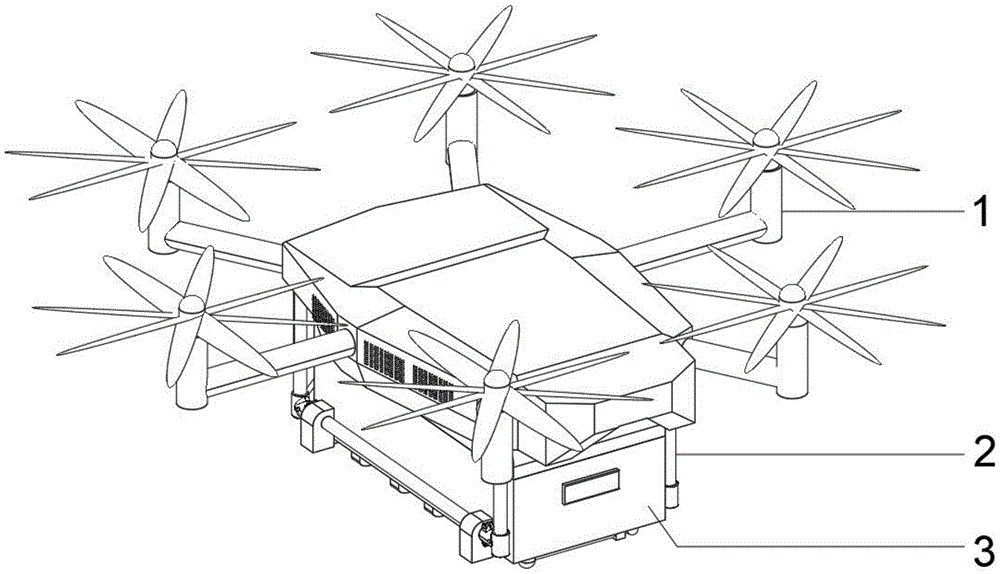
Unmanned aerial vehicle of navigating back automatically of no medicine
Technical Field
The utility model relates to an unmanned air vehicle technique field specifically is an automatic unmanned aerial vehicle that navigates back of no medicine.
Background
The unmanned aerial vehicle has wide application, can be used for military and can also be used for civil and scientific research. The maneuverability of a multi-rotor unmanned aerial vehicle is realized by changing the torque force and the rotating speed of different rotors. Compare traditional single horizontal rotor helicopter, many rotor unmanned aerial vehicle's structure is retrencied, easy to maintain, easy and simple to handle, stability is high and convenient to carry, and unmanned aerial vehicle also makes very big contribution in the technique of agricultural pesticide application. However, when traditional unmanned aerial vehicle gave medicine to, the majority was only at the inside electron water level induction instrument that adds of medical kit, because soak in aqueous for a long time, so break down very easily, leads to the phenomenon that unmanned aerial vehicle liquid medicine still was flying work after spraying. Therefore, the utility model provides an unmanned aerial vehicle that navigates back automatically of no medicine to solve the problem that proposes in the above-mentioned background art.
Disclosure of Invention
An object of the utility model is to provide an unmanned aerial vehicle that navigates back automatically of no medicine to solve the problem that proposes in the above-mentioned background art.
In order to achieve the above object, the utility model provides a following technical scheme:
the unmanned aerial vehicle without the pesticide for automatic return voyage comprises an unmanned aerial vehicle body, wherein a mounting rack is arranged on the bottom surface of the unmanned aerial vehicle body, a box body is placed on the mounting rack, a plurality of sprinkling pipes are arranged on the bottom surface of the box body, holes are formed in the sprinkling pipes and provided with atomizing nozzles, a sensor is arranged on one side wall of the box body, a water storage tank is arranged on one side of the interior of the box body, a buoy mechanism is arranged in the middle of one side of the water storage tank, a hose is arranged on one side of the buoy mechanism, one end of the hose is connected to the interior of the water storage tank, and a material conveying pump is connected to the other end of the hose;
the water storage tank is characterized in that a plurality of limiting strips are fixed on the front outer side wall and the rear outer side wall of the water storage tank, a groove is formed in the tank body, the water storage tank is arranged in the tank body through a plurality of limiting strip limiting installers on the outer side wall, a plurality of buffer springs are arranged on the surface of the bottom of the water storage tank, a weighing inductor is arranged below the buffer springs, the bottom of the water storage tank is arranged in the tank body through the buffer springs and the weighing inductor, a sealing plate is arranged at the top of the water storage tank, and;
the buoy mechanism comprises a buoy, a limiting rod, a first inductor, a second inductor, a buoy block and a power line;
the utility model discloses a water storage tank, including the buoy, the gag lever post is installed on the storage water tank, the centre of a circle department of buoy is fixed with the gag lever post, the top of gag lever post is equipped with inductor one, and the bottom of gag lever post is equipped with inductor two, be equipped with the kicking block between inductor one and the inductor two, the kicking block cover is established inside the gag lever post.
As the utility model discloses further scheme, defeated material pump one side is passed through the hose connection in the inside of storage water tank, and defeated material pump opposite side is equipped with connecting pipe one through the hose.
As the utility model discloses the scheme of furtherly again, connecting pipe one-tenth is on the sprinkler pipe, and the sprinkler pipe passes through connecting pipe one-tenth to be connected on the hose on the conveying pump.
As the utility model discloses scheme further still, inductor one and inductor two all carry out interconnect through the power cord, and power cord one end is connected on inductor one and inductor two, and the connection of the power cord other end is equipped with the controller.
As the utility model discloses scheme further again, controller one side is equipped with the battery, controller and battery all are located the inside of box.
As the utility model discloses scheme further again, the top surface one end of box is equipped with siren and feed inlet, the feed inlet is connected on two connecting pipes on the storage water tank.
Compared with the prior art, the beneficial effects of the utility model are that:
1. the utility model discloses, during the flight, through the flight route of terminal device control unmanned aerial vehicle body, and during the pesticide application take out the liquid medicine in with the water storage tank through starting the conveying pump and transmit the liquid medicine to the sprinkler pipe through the hose, the liquid medicine in the sprinkler pipe is atomized the liquid medicine and is spilled through atomizer to reach the effect of pesticide application.
2. The utility model discloses, when the inside liquid medicine of storage water tank reached the certain degree, the floating block on the buoy mechanism descends along with the liquid medicine on the one hand to make the floating block touch inductor two, inductor two signals are in with information feedback to the controller, the controller starts the siren and with information feedback to the sensor in, the sensor is passing through this body coupling terminating set of unmanned aerial vehicle, thereby the unnecessary unmanned aerial vehicle body of signal control returns to navigate and adds the medicine.
Drawings
Fig. 1 is a schematic structural view of a drug-free automatic return unmanned aerial vehicle.
Fig. 2 is a schematic view of the upward structure of a drug-free automatic return unmanned aerial vehicle.
Fig. 3 is a schematic structural diagram of a box body in a drug-free automatic return unmanned aerial vehicle.
Fig. 4 is an internal structure schematic diagram of a box body in a drug-free automatic return unmanned aerial vehicle.
Fig. 5 is a schematic view of the internal side view of the case body of the drug-free automatic return unmanned aerial vehicle.
Fig. 6 is a schematic structural diagram of a buoy mechanism in a drug-free automatic return unmanned aerial vehicle.
In the figure: 1. an unmanned aerial vehicle body; 2. a mounting frame; 3. a box body; 4. a sprinkler pipe; 5. a water storage tank; 6. a first connecting pipe; 7. a sensor; 8. a sealing plate; 9. a second connecting pipe; 10. a buffer spring; 11. a weighing sensor; 12. a float mechanism; 121. a float bowl; 122. a limiting rod; 123. a first inductor; 124. a second inductor; 125. floating blocks; 126. a power line; 13. a delivery pump; 14. a hose; 15. a controller; 16. a storage battery; 17. an alarm; 18. a feed inlet; 19. and (5) a limiting strip.
Detailed Description
The technical solutions in the embodiments of the present invention will be described clearly and completely with reference to the accompanying drawings in the embodiments of the present invention, and it is obvious that the described embodiments are only some embodiments of the present invention, not all embodiments. Based on the embodiments in the present invention, all other embodiments obtained by a person skilled in the art without creative work belong to the protection scope of the present invention.
Referring to fig. 1 to 6, in an embodiment of the present invention, a drug-free automatic return unmanned aerial vehicle includes an unmanned aerial vehicle body 1, a mounting frame 2 is disposed on a bottom surface of the unmanned aerial vehicle body 1, a tank body 3 is disposed on the mounting frame 2, a plurality of water sprinkling pipes 4 are disposed on the bottom surface of the tank body 3, a hole is formed in each water sprinkling pipe 4 and is provided with an atomizing nozzle, a sensor 7 is mounted on a side wall of the tank body 3, a water storage tank 5 is disposed on one side of the inside of the tank body 3, a buoy mechanism 12 is mounted in the middle of one side of the water storage tank 5, a hose 14 is disposed on one side of the buoy mechanism 12, one end of the hose 14 is connected to the inside of the water storage tank 5, a material delivery pump 13 is connected to the other end of the hose 14, one side of the material delivery pump 13 is connected to the inside of the water storage tank 5 through the hose 14, the other side of the material delivery pump 13 is provided with a first connecting pipe 6 through the hose 14, the first connecting pipe 6 is connected to the water sprinkling pipe 4, the sprinkling pipe 4 is connected with a hose 14 on a material conveying pump 13 through a first connecting pipe 6;
all be fixed with a plurality of spacing strips 19 on the lateral wall around storage water tank 5, the inside fluting of box 3, storage water tank 5 pass through the spacing installer of a plurality of spacing strips 19 of lateral wall in box 3, storage water tank 5's bottom is equipped with a plurality of buffer spring 10 on the surface, buffer spring 10's below is equipped with weighing inductor 11, storage water tank 5 bottom is passed through buffer spring 10 and weighing inductor 11 and is installed in the inside of box 3, and storage water tank 5's top is equipped with closing plate 8, and trompil is gone up to closing plate 8 and is equipped with connecting pipe two 9, the top surface one end of box 3 is equipped with siren 17 and feed inlet 18, feed inlet 18 is connected on connecting pipe two 9 on storage water tank 5.
The buoy mechanism 12 comprises a buoy 121, a limiting rod 122, a first inductor 123, a second inductor 124, a floating block 125 and a power line 126, wherein the first inductor 123 and the second inductor 124 are connected with each other through the power line 126, one end of the power line 126 is connected to the first inductor 123 and the second inductor 124, the other end of the power line 126 is connected with a controller 15, a storage battery 16 is arranged on one side of the controller 15, and the controller 15 and the storage battery 16 are both located inside the box body 3.
The utility model discloses a float bowl 121, including float bowl 121, gag lever post 122, floater 125, gag lever post 122, float block 125 cover, the buoy 121 is installed on storage water tank 5, the centre of a circle department of float bowl 121 is fixed with gag lever post 122, the top of gag lever post 122 is equipped with inductor 123, and the bottom of gag lever post 122 is equipped with inductor two 124, be equipped with floater 125 between inductor 123 and the inductor two 124, the floater 125 cover is established inside gag lever post 122.
The utility model discloses a theory of operation is:
the utility model is connected to the unmanned aerial vehicle body 1 through the terminal device when in use, and the sensor 7 arranged on the box body 3 is connected to the terminal device through the unmanned aerial vehicle body 1;
during flying, the flying path of the unmanned aerial vehicle body 1 is controlled through the terminal device, during pesticide application, the pesticide liquid in the water storage tank 5 is pumped out by starting the material conveying pump 13 and is transmitted to the sprinkling pipe 4 through the hose 14, and the pesticide liquid in the sprinkling pipe 4 is atomized and sprinkled through the atomizing nozzle, so that the pesticide application effect is achieved;
when the liquid medicine in the water storage tank 5 reaches a certain degree, on one hand, the floating block 125 on the buoy mechanism 12 descends along with the liquid medicine, so that the floating block 125 touches the second inductor 124, the second inductor 124 sends a signal to feed information back to the controller 15, the controller 15 starts the alarm 17 and feeds the information back to the sensor 7, the sensor 7 is connected with a terminal device through the unmanned aerial vehicle body 1, and therefore the signal is sent to control the unnecessary unmanned aerial vehicle body 1 to carry out return voyage dosing;
when the liquid medicine is added into the water storage tank 5 through the feed port 18, the weight of the water storage tank 5 is measured by the weighing sensor 11 at any moment along with the weight increase of the water storage tank 5 for adding the liquid medicine, when the weight of the added liquid medicine in the water storage tank 5 reaches a certain degree, the weight reaches a certain value, the weighing sensor 11 feeds back information to the controller 15, and therefore the purpose of checking and controlling the amount of the liquid medicine in the water storage tank 5 by measuring the weight of the water storage tank 5 is achieved;
under the dual detection of buoy mechanism 12 and weighing inductor 11 to guarantee unmanned aerial vehicle body 1 at the during operation, the numerical value of liquid medicine.
The above, only be the concrete implementation of the preferred embodiment of the present invention, but the protection scope of the present invention is not limited thereto, and any person skilled in the art is in the technical scope of the present invention, according to the technical solution of the present invention and the utility model, the concept of which is equivalent to replace or change, should be covered within the protection scope of the present invention.