CN213968662U - Cooling device before wheel hub spinning - Google Patents
Cooling device before wheel hub spinning Download PDFInfo
- Publication number
- CN213968662U CN213968662U CN202022371769.8U CN202022371769U CN213968662U CN 213968662 U CN213968662 U CN 213968662U CN 202022371769 U CN202022371769 U CN 202022371769U CN 213968662 U CN213968662 U CN 213968662U
- Authority
- CN
- China
- Prior art keywords
- placing table
- plate
- cooling
- hub
- sides
- Prior art date
- Legal status (The legal status is an assumption and is not a legal conclusion. Google has not performed a legal analysis and makes no representation as to the accuracy of the status listed.)
- Expired - Fee Related
Links
- 238000001816 cooling Methods 0.000 title claims abstract description 44
- 238000009987 spinning Methods 0.000 title claims abstract description 18
- 230000007246 mechanism Effects 0.000 claims abstract description 35
- XLYOFNOQVPJJNP-UHFFFAOYSA-N water Substances O XLYOFNOQVPJJNP-UHFFFAOYSA-N 0.000 claims description 14
- 238000005507 spraying Methods 0.000 claims description 13
- 239000000110 cooling liquid Substances 0.000 claims description 8
- 238000005485 electric heating Methods 0.000 claims description 8
- 239000007921 spray Substances 0.000 claims description 4
- 230000000694 effects Effects 0.000 abstract description 8
- 238000004321 preservation Methods 0.000 abstract 1
- 239000007788 liquid Substances 0.000 description 4
- 238000004512 die casting Methods 0.000 description 3
- 238000010438 heat treatment Methods 0.000 description 3
- 239000002826 coolant Substances 0.000 description 2
- 238000003754 machining Methods 0.000 description 2
- 239000002184 metal Substances 0.000 description 2
- 230000000149 penetrating effect Effects 0.000 description 2
- 229910000831 Steel Inorganic materials 0.000 description 1
- 230000009471 action Effects 0.000 description 1
- 239000011324 bead Substances 0.000 description 1
- 239000000498 cooling water Substances 0.000 description 1
- 238000009434 installation Methods 0.000 description 1
- 238000010030 laminating Methods 0.000 description 1
- 238000004519 manufacturing process Methods 0.000 description 1
- 239000000463 material Substances 0.000 description 1
- 238000012986 modification Methods 0.000 description 1
- 230000004048 modification Effects 0.000 description 1
- 238000007493 shaping process Methods 0.000 description 1
- 239000010959 steel Substances 0.000 description 1
Images




Landscapes
- Spinning Methods And Devices For Manufacturing Artificial Fibers (AREA)
Abstract
The utility model discloses a cooling device before spinning of a hub, which comprises a barrel placing table, wherein clamping mechanisms are arranged on two sides of a bottom plate of the placing table, a cooling mechanism is arranged on a side plate of the placing table, the clamping mechanisms are fixedly connected with the bottom plate of the placing table, and the cooling mechanism is connected with the placing table in a sliding manner; the surface of placing the platform is equipped with recess and sponge, the recess set up in place the bottom plate top of platform and be located two sets of between the clamping mechanism, sponge activity joint in the recess, clamping mechanism includes fixed plate, telescopic link, reset spring, first slider, first spout, supports tight board and electric heat piece, first slider symmetry install in one side of fixed plate. The utility model relates to a can be to the cooling of specified region, heat the heat preservation to the wheel hub lateral wall, improve the wheel hub spinning front cooling device of spinning effect.
Description
The technical field is as follows:
the utility model relates to a wheel hub processing equipment technical field specifically is a cooling device before wheel hub spinning.
Background art:
the wheel hub is a cylindrical metal component with the inner contour of the tire supporting the tire and the center of the metal component is arranged on a shaft, and is also called a rim, a steel ring, a wheel and a tire bead. The hub is various according to diameter, width, shaping mode, different types of material, in the production to the hub, need use more part and equipment, and cooling arrangement then is one of the accessories in the hub processing, and current hub needs to be heated the hub in the processing to the later stage is to the edge die-casting of hub.
However, the existing machining device is in the hub heating process, the whole hub is in an easily deformable state, so that when the edge of the die-casting hub is formed, the supporting part in the middle of the hub is deformed, the machining failure is caused, the whole hub is placed in water for cooling in the conventional cooling mode, the temperature of the edge of the whole wheel cannot meet the requirement, and the spinning effect can be influenced.
The utility model has the following contents:
an object of the utility model is to provide a cooling device before wheel hub spinning to solve current processingequipment in to the wheel hub heating, whole wheel hub all is in yielding state, thereby lead to when die-casting wheel hub edge, the supporting component of wheel hub intermediate position is the same can appear warping, cause the processing failure, current common cooling method is to place whole wheel hub in the aquatic cooling, whole wheel is chartered and can appear the temperature of edge again and can not reach the requirement, probably influence the problem of the effect of spinning.
The utility model discloses by following technical scheme implement: a cooling device before spinning of a wheel hub comprises a barrel placing table, clamping mechanisms are mounted on two sides of a bottom plate of the placing table, cooling mechanisms are mounted on side plates of the placing table, the clamping mechanisms are fixedly connected with the bottom plate of the placing table, and the cooling mechanisms are connected with the placing table in a sliding mode;
the surface of the placing table is provided with a groove and a sponge, the groove is formed in the top of a bottom plate of the placing table and located between the two groups of clamping mechanisms, and the sponge is movably clamped in the groove.
Preferably, the clamping mechanism comprises a fixed plate, a telescopic rod, a reset spring, a first sliding block, a first sliding groove, a tightening plate and an electric heating piece, the first sliding block is symmetrically arranged on one side of the fixed plate, the first sliding groove is formed in two sides of the bottom of the tightening plate, the tightening plate is connected with the first sliding block in a sliding mode through the first sliding groove, the telescopic rod is connected between the tightening plate and the fixed plate, the reset spring is sleeved on the telescopic rod, and the electric heating piece is arranged in the tightening plate.
Preferably, the two fixing plates are respectively installed on two sides of the placing table, the inner side of the abutting plate is arc-shaped, and the reset spring is in an extension state by default.
Preferably, the cooling mechanism comprises a hydraulic cylinder, a hydraulic guide rod, a second slider, a movable plate, an annular spraying pipe, a water inlet pipe and a second sliding groove, the second sliding groove is formed in the two ends of one side of the movable plate, the movable plate is connected with the second slider in a sliding mode through the second sliding groove, the hydraulic rod of the hydraulic cylinder and the hydraulic guide rod are fixedly connected with the top of the movable plate, the annular spraying pipe is installed on the top of the movable plate, and the water inlet pipe is connected to the two sides of the annular spraying pipe in a penetrating mode.
Preferably, a boss is arranged at the top of a side plate of the placing table, the hydraulic cylinder is mounted in the middle of the top of the boss, the hydraulic guide rods are mounted at the top of the boss and located on two sides of the hydraulic cylinder, and the second sliding blocks are mounted on two sides of the side plate of the placing table.
Preferably, the top of the annular spraying pipe is provided with an atomizing nozzle.
Preferably, the top of the side plate of the placing table is positioned on two sides of the boss, clamping rings are installed on two sides of the boss, one end of the water inlet pipe is communicated with the annular spraying pipe, and the other end of the water inlet pipe penetrates through the clamping rings to be connected with a high-pressure pump of external cooling liquid.
The utility model has the advantages that:
1. the utility model discloses be equipped with clamping mechanism, be convenient for pass through clamping mechanism quick clamping and heat conduction with wheel hub, through placing wheel hub between two tight boards, make two tight boards support and drive under reset spring's the effect of stretching and support tight board and move and then support tight wheel hub's lateral wall on first slider, be the arc through supporting tight board, support the laminating wheel hub lateral wall that tight board can be better, support tight back and heat the wheel hub lateral wall through supporting the electric heat piece of tight inboard installation to make wheel hub can keep warm through the lateral wall to wheel hub when cooling down to the frontal supporting part in middle, avoid the cooling of wheel hub lateral wall to influence the effect of spinning.
2. The utility model is provided with a cooling mechanism, the supporting part in the middle of the wheel hub can be cooled through the cooling mechanism, the hydraulic cylinder is started after the wheel hub is placed, the movable plate is pushed to descend on the second slider through the hydraulic cylinder, so that the annular spray pipe arranged at the bottom of the movable plate extends into the interior of the wheel hub to be attached to the supporting part, the high-pressure pump connected with a water inlet pipe is started, the cooling liquid enters the annular spray pipe through the water inlet pipe and is sprayed out through the atomizing nozzle, the atomized liquid sprayed out through the atomizing nozzle can be quickly evaporated by the high temperature of the supporting part, thereby realizing heat replacement and fast cooling, the cooling placement can cool the appointed area of the wheel hub, compared with the cooling liquid directly sprayed by the cooling water, the cooling liquid can be saved, the cooling effect is better, the redundant cooling liquid can be absorbed through the sponge, the utility model is capable of cooling the appointed area, the cooling device before wheel hub spinning improves the spinning effect by heating and insulating the side wall of the wheel hub.
Description of the drawings:
in order to more clearly illustrate the embodiments of the present invention or the technical solutions in the prior art, the drawings used in the description of the embodiments or the prior art will be briefly described below, it is obvious that the drawings in the following description are only some embodiments of the present invention, and for those skilled in the art, other drawings can be obtained according to these drawings without creative efforts.
FIG. 1 is a schematic view of the structure of the present invention;
fig. 2 is a schematic structural view of the clamping mechanism of fig. 1 according to the present invention;
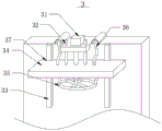
fig. 3 is a schematic structural view of the cooling mechanism of fig. 1 according to the present invention;
FIG. 4 is a schematic structural view of the annular shower pipe of the present invention;
fig. 5 is a schematic view of a cross-sectional structure of the tightening plate of the present invention.
In the figure: 1. a placing table; 101. a boss; 2. a clamping mechanism; 21. a fixing plate; 22. a telescopic rod; 23. a return spring; 24. a first slider; 25. a first chute; 26. a propping plate; 27. an electric heating sheet; 3. a cooling mechanism; 31. a hydraulic cylinder; 32. a hydraulic guide rod; 33. a second slider; 34. a movable plate; 35. an annular shower pipe; 36. a water inlet pipe; 37. a second chute; 38. an atomizing spray head; 4. a snap ring; 5. a groove; 6. a sponge.
The specific implementation mode is as follows:
the technical solutions in the embodiments of the present invention will be described clearly and completely with reference to the accompanying drawings in the embodiments of the present invention, and it is obvious that the described embodiments are only some embodiments of the present invention, not all embodiments. Based on the embodiments in the present invention, all other embodiments obtained by a person skilled in the art without creative efforts belong to the protection scope of the present invention.
Referring to FIGS. 1-5: a cooling device before spinning of a wheel hub comprises a barrel placing table 1, clamping mechanisms 2 are mounted on two sides of a bottom plate of the placing table 1, cooling mechanisms 3 are mounted on side plates of the placing table 1, the clamping mechanisms 2 are fixedly connected with the bottom plate of the placing table 1, and the cooling mechanisms 3 are connected with the placing table 1 in a sliding mode;
the surface of the placing table 1 is provided with a groove 5 and a sponge 6, the groove 5 is arranged at the top of a bottom plate of the placing table 1 and is positioned between the two groups of clamping mechanisms 2, and the sponge 6 is movably clamped in the groove 5.
The clamping mechanism 2 comprises a fixing plate 21, an expansion link 22, a reset spring 23, a first sliding block 24, a first sliding groove 25, a resisting plate 26 and an electric heating piece 27, the first sliding block 24 is symmetrically installed on one side of the fixing plate 21, the first sliding groove 25 is formed in two sides of the bottom of the resisting plate 26, the resisting plate 26 is connected with the first sliding block 24 in a sliding mode through the first sliding groove 25, the expansion link 22 is connected between the resisting plate 26 and the fixing plate 21, the reset spring 23 is sleeved on the expansion link 22, the electric heating piece 27 is installed in the resisting plate 26, and the wheel hub is clamped fast and conducts heat through the clamping mechanism 2.
The two fixing plates 21 are respectively installed on two sides of the placing table 1, the inner side of the abutting plate 26 is arc-shaped, and the reset spring 23 is in an extending state by default, so that the abutting plate 26 is kept in an abutting state through the reset spring 23.
The cooling mechanism 3 includes a hydraulic cylinder 31, a hydraulic guide rod 32, a second slider 33, a movable plate 34, an annular spraying pipe 35, a water inlet pipe 36 and a second chute 37, the second chute 37 is opened at both ends of one side of the movable plate 34, the movable plate 34 is slidably connected with the second slider 33 through the second chute 37, the hydraulic rod of the hydraulic cylinder 31 and the hydraulic guide rod 32 are fixedly connected with the top of the movable plate 34, the annular spraying pipe 35 is installed at the top of the movable plate 34, the water inlet pipe 36 is connected to both sides of the annular spraying pipe 35 in a penetrating manner, the hydraulic cylinder 31 is started, the movable plate 34 is pushed by the hydraulic cylinder 31 to descend on the second slider 33, and the annular spraying pipe 35 installed at the bottom of the movable plate 34 extends into the interior of the wheel hub to be attached to the supporting portion, so as to cool the wheel hub.
The top of the side plate of the placing table 1 is provided with a boss 101, the hydraulic cylinder 31 is installed in the middle of the top of the boss 101, the hydraulic guide rods 32 are installed at the top of the boss 101 and located at two sides of the hydraulic cylinder 31, and the second sliders 33 are installed at two sides of the side plate of the placing table 1, so that the movable plate 34 can be pushed to ascend and descend through the hydraulic cylinder 31.
The top of the annular spraying pipe 35 is provided with an atomizing nozzle 38, and the area can be cooled more quickly and the cooling liquid can be saved through the atomizing nozzle 38.
The curb plate top of placing platform 1 is located snap ring 4 is installed to the both sides of boss 101, the one end of inlet tube 36 with annular shower 35 through connection, the other end of inlet tube 36 passes snap ring 4 is connected with the high-pressure pump of outside coolant liquid, starts the high-pressure pump that inlet tube 36 is connected, and the coolant liquid enters into annular shower 35 through inlet tube 36 and via atomizer 38 blowout.
When the utility model is used, firstly, the wheel hub is placed between the two tightening plates 26, the two tightening plates 26 drive the tightening plate 26 to move on the first slider 24 under the stretching action of the reset spring 23 so as to tighten the side wall of the wheel hub, the tightening plate 26 is arc-shaped, the tightening plate 26 can be better attached to the side wall of the wheel hub, after tightening, the side wall of the wheel hub is heated by the electric heating sheet 27 arranged in the tightening plate 26, then the movable plate 34 is pushed to descend on the second slider 33 through the hydraulic cylinder 31, further the annular spraying pipe 35 arranged at the bottom of the movable plate 34 is extended into the wheel hub to be attached to the supporting part, the high pressure pump connected with the water inlet pipe 36 is started, the cooling liquid enters the annular spraying pipe 35 through the water inlet pipe 36 and is sprayed out through the atomizing nozzle 38, the atomized liquid sprayed out through the atomizing nozzle 38 can be quickly evaporated by the high temperature of the supporting part, further the heat replacement can be realized, and (5) rapidly cooling.
The above description is only a preferred embodiment of the present invention, and should not be taken as limiting the invention, and any modifications, equivalent replacements, improvements, etc. made within the spirit and principle of the present invention should be included in the protection scope of the present invention.
Claims (7)
1. The cooling device before spinning of the wheel hub comprises a barrel placing table (1), clamping mechanisms (2) are mounted on two sides of a bottom plate of the placing table (1), and cooling mechanisms (3) are mounted on side plates of the placing table (1), and is characterized in that the clamping mechanisms (2) are fixedly connected with the bottom plate of the placing table (1), and the cooling mechanisms (3) are connected with the placing table (1) in a sliding mode;
the surface of the placing table (1) is provided with a groove (5) and a sponge (6), the groove (5) is arranged at the top of a bottom plate of the placing table (1) and is located between the two groups of clamping mechanisms (2), and the sponge (6) is movably clamped in the groove (5).
2. A hub pre-flow cooling apparatus as claimed in claim 1, wherein: the clamping mechanism (2) comprises a fixing plate (21), an expansion link (22), a reset spring (23), a first sliding block (24), a first sliding groove (25), a tightening plate (26) and an electric heating piece (27), wherein the first sliding block (24) is symmetrically arranged on one side of the fixing plate (21), the first sliding groove (25) is formed in two sides of the bottom of the tightening plate (26), the tightening plate (26) is in sliding connection with the first sliding block (24) through the first sliding groove (25), the expansion link (22) is connected between the tightening plate (26) and the fixing plate (21), the reset spring (23) is sleeved on the expansion link (22), and the electric heating piece (27) is arranged in the tightening plate (26).
3. A hub pre-flow cooling apparatus as claimed in claim 2, wherein: the two fixing plates (21) are respectively installed on two sides of the placing table (1), the inner side of the abutting plate (26) is arc-shaped, and the reset spring (23) is in an extending state in a default mode.
4. A hub pre-flow cooling apparatus as claimed in claim 1, wherein: cooling body (3) include pneumatic cylinder (31), hydraulic pressure guide arm (32), second slider (33), fly leaf (34), annular shower (35), inlet tube (36) and second spout (37), second spout (37) are seted up in the both ends of fly leaf (34) one side, fly leaf (34) are passed through second spout (37) with second slider (33) sliding connection, the hydraulic stem of pneumatic cylinder (31) with hydraulic pressure guide arm (32) with the top fixed connection of fly leaf (34), annular shower (35) install in the top of fly leaf (34), inlet tube (36) through-connection in the both sides of annular shower (35).
5. A hub before-spinning cooling device according to claim 4, wherein: the top of a side plate of the placing table (1) is provided with a boss (101), the hydraulic cylinder (31) is installed in the middle of the top of the boss (101), the hydraulic guide rods (32) are installed at the top of the boss (101) and located on two sides of the hydraulic cylinder (31), and the second sliding blocks (33) are installed on two sides of the side plate of the placing table (1).
6. The cooling device before spinning of the hub of claim 5, wherein: and the top of the annular spray pipe (35) is provided with an atomizing nozzle (38).
7. The cooling device before spinning of the hub of claim 6, wherein: the top of the side plate of the placing table (1) is located clamping rings (4) are installed on two sides of a boss (101), one end of the water inlet pipe (36) is communicated with the annular spraying pipe (35), and the other end of the water inlet pipe (36) penetrates through the clamping rings (4) to be connected with a high-pressure pump of external cooling liquid.
Priority Applications (1)
| Application Number | Priority Date | Filing Date | Title |
|---|---|---|---|
| CN202022371769.8U CN213968662U (en) | 2020-10-22 | 2020-10-22 | Cooling device before wheel hub spinning |
Applications Claiming Priority (1)
| Application Number | Priority Date | Filing Date | Title |
|---|---|---|---|
| CN202022371769.8U CN213968662U (en) | 2020-10-22 | 2020-10-22 | Cooling device before wheel hub spinning |
Publications (1)
| Publication Number | Publication Date |
|---|---|
| CN213968662U true CN213968662U (en) | 2021-08-17 |
Family
ID=77258204
Family Applications (1)
| Application Number | Title | Priority Date | Filing Date |
|---|---|---|---|
| CN202022371769.8U Expired - Fee Related CN213968662U (en) | 2020-10-22 | 2020-10-22 | Cooling device before wheel hub spinning |
Country Status (1)
| Country | Link |
|---|---|
| CN (1) | CN213968662U (en) |
Cited By (2)
| Publication number | Priority date | Publication date | Assignee | Title |
|---|---|---|---|---|
| CN113560454A (en) * | 2021-09-26 | 2021-10-29 | 南通市通州区袁灶燃气有限公司 | Stamping device is used in processing of liquefied petroleum gas jar |
| CN116422819A (en) * | 2022-12-16 | 2023-07-14 | 驻马店恒久机械制造有限公司 | A fully automatic multi-mode vertical rolling machine |
-
2020
- 2020-10-22 CN CN202022371769.8U patent/CN213968662U/en not_active Expired - Fee Related
Cited By (2)
| Publication number | Priority date | Publication date | Assignee | Title |
|---|---|---|---|---|
| CN113560454A (en) * | 2021-09-26 | 2021-10-29 | 南通市通州区袁灶燃气有限公司 | Stamping device is used in processing of liquefied petroleum gas jar |
| CN116422819A (en) * | 2022-12-16 | 2023-07-14 | 驻马店恒久机械制造有限公司 | A fully automatic multi-mode vertical rolling machine |
Similar Documents
| Publication | Publication Date | Title |
|---|---|---|
| CN107377774A (en) | The bounce-proof formula diel that can cool | |
| CN210940503U (en) | Hot melting machine with positioning structure | |
| CN208374584U (en) | Flange welding Deformation control equipment | |
| CN210333993U (en) | Stamping die with cooling function | |
| CN211493151U (en) | Multi-layer composite device for functional fiber fabric | |
| CN210938371U (en) | Portable cooling device for hardware machining | |
| CN208604189U (en) | Hydraulic support column Multi-station automatic hot spray apparatus | |
| CN115430827A (en) | Automatic quick cooling device of location | |
| CN211992084U (en) | Workpiece cooling device for machine tool machining | |
| CN215998601U (en) | Automobile engine lower cylinder casting device capable of performing local cooling | |
| CN222679507U (en) | Motor housing mold frame | |
| CN224158885U (en) | A welding device for an instrument cover assembly | |
| CN221311280U (en) | Spray gun for glue spraying machine | |
| CN219052822U (en) | Tantalum and niobium cooling device with water vapor recovery function | |
| CN216115390U (en) | Electric furnace with good heat dissipation effect | |
| CN109130116A (en) | A kind of demoulding equipment of technique for aircraft composite part | |
| CN218612121U (en) | Protection mechanism of cold and hot seamless hot press | |
| CN113458658A (en) | Circumferential annular welding device | |
| CN215063144U (en) | Gas cooling device of dispensing machine | |
| CN217182273U (en) | Heat exchange module of new energy automobile | |
| JPH0647008Y2 (en) | Inner quenching device | |
| CN219260110U (en) | Heat treatment water mist cooling system | |
| CN221208658U (en) | Paint spraying equipment with drying structure | |
| CN221414213U (en) | High-temperature high-pressure steam cleaning device | |
| CN224254195U (en) | A rapid die-casting equipment for generator end caps made of aluminum alloy |
Legal Events
| Date | Code | Title | Description |
|---|---|---|---|
| GR01 | Patent grant | ||
| GR01 | Patent grant | ||
| CF01 | Termination of patent right due to non-payment of annual fee | ||
| CF01 | Termination of patent right due to non-payment of annual fee |
Granted publication date: 20210817 |