CN214110901U - Support stable mixing arrangement for concrete processing - Google Patents
Support stable mixing arrangement for concrete processing Download PDFInfo
- Publication number
- CN214110901U CN214110901U CN202022342066.2U CN202022342066U CN214110901U CN 214110901 U CN214110901 U CN 214110901U CN 202022342066 U CN202022342066 U CN 202022342066U CN 214110901 U CN214110901 U CN 214110901U
- Authority
- CN
- China
- Prior art keywords
- base
- water
- mixing
- tank
- mixing tank
- Prior art date
- Legal status (The legal status is an assumption and is not a legal conclusion. Google has not performed a legal analysis and makes no representation as to the accuracy of the status listed.)
- Expired - Fee Related
Links
Images



Landscapes
- Preparation Of Clay, And Manufacture Of Mixtures Containing Clay Or Cement (AREA)
Abstract
The utility model discloses a support stable mixing arrangement for concrete processing, which comprises a base and a mixing tank, wherein the mixing tank is arranged at the upper end of the base, a mounting groove is processed at the upper surface of the base, an operator can install the mixing tank at the inner side of the mounting groove, meanwhile, a fixing plate is arranged at the upper surface of the base, a threaded rod penetrates through the fixing plate and is movably connected with an arc-shaped plate, the arc-shaped plate is enabled to be close to the outer surface of the mixing tank by rotating the threaded rod, when two groups of arc-shaped plates are tightly attached to the outer wall of the mixing tank, the rotation is stopped, the mixing tank is fixedly arranged at the upper end of the base, the stabilizing effect is good, a driving motor drives a driving gear to rotate, the driving gear is meshed with a driven gear, the driven gear drives a connecting rod and a mixing piece to rotate, the raw materials are convenient to be mixed, water in a water tank is injected into the mixing tank through a water injection pipe and a spray head by utilizing a water pump, the concrete water supply device can supply water to the concrete and prevent the concrete from caking due to water loss.
Description
Technical Field
The utility model relates to a concrete processing equipment technical field specifically is a support stable mixing arrangement for concrete processing.
Background
The common concrete is artificial stone which is prepared by taking cement as a main cementing material, adding water, sand, stones and chemical additives and mineral admixtures if necessary, mixing the materials according to a proper proportion, uniformly stirring, densely molding, curing and hardening. Concrete is mainly divided into two stages and states: plastic state before setting and hardening, namely fresh concrete or concrete mixture; hardened, i.e. hardened concrete or concrete.
At present, the in-process that mixes is carried out at the concrete, because the stirring of internal stirring structure to the raw materials makes the blending tank probably produce the shake, and stability is not very good, and in concrete mixing process, can not in time supply moisture, leads to the raw materials lack of water and the caking, influences the use.
To the above problem, the utility model provides a support stable mixing arrangement for concrete processing.
SUMMERY OF THE UTILITY MODEL
An object of the utility model is to provide a support stable mixing arrangement for concrete processing, it is effectual to have possessed stable, facilitates the use, and can conveniently supply moisture, prevents the advantage of caking to the problem in the background art has been solved.
In order to achieve the above object, the utility model provides a following technical scheme: a stably supported mixing device for concrete processing comprises a base and a mixing tank, wherein the mixing tank is arranged at the upper end of the base, the base comprises a mounting groove, a supporting rod, a stabilizing structure and an auxiliary plate, the mounting groove is processed on the upper surface of the base, the supporting rod is arranged at the lower end of the base, the stabilizing structure is arranged at the upper end of the base, and the auxiliary plate is fixedly arranged on one side of the base;
the blending tank comprises a feed inlet, a fixing seat, a water injection structure, a packing structure, an observation window, a discharging pipe and a non-stick layer, wherein the feed inlet is arranged at the upper end of the blending tank, the fixing seat is arranged at one side of the feed inlet, the water injection structure is arranged at one side of the blending tank and is arranged at the upper end of an auxiliary plate, the packing structure is arranged at the upper end of the base, the observation window is arranged on the surface of the blending tank, the discharging pipe is arranged at the lower end of the blending tank, and the non-stick layer is arranged on the inner wall of the blending tank.
Preferably, the stable structure includes fixed plate, threaded rod and arc, and fixed plate fixed mounting is in the upper end of base, and the threaded rod runs through the fixed plate, and the other end and the arc swing joint of threaded rod.
Preferably, the fixing base includes driving motor, driving gear and driven structure, and driving motor sets up in the upper end of fixing base, and driving motor's output is connected with the driving gear, and driven structure sets up the one side at the driving gear.
Preferably, the driven structure includes driven gear, connecting rod and mixing piece, and driven gear sets up in one side of driving gear, and driven gear and driving gear mesh mutually, and the connecting rod setting is at driven gear's lower extreme, and the mixing piece setting is in one side of connecting rod.
Preferably, the water injection structure includes water tank, water pump, drinking-water pipe, water injection pipe and shower nozzle, and the water tank setting is in the upper end of accessory plate, and the water pump setting is in the inside of water tank, and the one end of water pump is connected with the drinking-water pipe, and the other end is connected with the water injection pipe, and the shower nozzle setting is in one side of water injection pipe, and sets up the inside at the blending tank.
Preferably, the filler structure includes delivery pump, connecting plate, feed hopper and conveying pipeline, and the delivery pump setting passes through connecting plate fixed mounting in one side of blending tank with the base, and feed hopper sets up in the upper end of delivery pump, and the conveying pipeline setting is in one side of delivery pump, and the other end of conveying pipeline is connected with the blending tank.
Preferably, a valve is arranged on one side of the blanking pipe.
Preferably, the fixing structures are arranged in two groups, and the two groups of fixing structures are symmetrically distributed about the longitudinal center line of the base.
Compared with the prior art, the beneficial effects of the utility model are as follows:
1. the utility model provides a support stable mixing arrangement for concrete processing, the upper surface processing of base has the mounting groove, and operating personnel can install the blending tank in the inboard of mounting groove, is provided with the fixed plate simultaneously at the upper surface of base, and the threaded rod runs through the fixed plate, and with arc swing joint, through rotating the threaded rod, makes the arc be close to the surface of blending tank, when two sets of arcs hug closely the outer wall of blending tank, stops rotating, makes the blending tank fixed mounting in the upper end of base, and stabilizing effect is good;
2. the utility model provides a support stable mixing arrangement for concrete processing, the upper end of blending tank is provided with the feed inlet, the raw materials can be put into the inside of blending tank from the feed inlet, driving motor sets up the upper end at the fixing base, driving motor's output is connected with the driving gear, driving motor drive driving gear rotates, and the driving gear meshes with driven gear mutually, make driven gear drive connecting rod and mixing piece rotate, be convenient for mix the raw materials, be provided with the water tank in one side of blending tank simultaneously, utilize the water pump to inject the water in the water tank into the blending tank through water injection pipe and shower nozzle, can supply moisture for the concrete, prevent that moisture lacks and lead to the concrete caking;
3. the utility model provides a support stable mixing arrangement for concrete processing is provided with the delivery pump in the upper end of base, and the delivery pump passes through connecting plate fixed mounting with the base, and operating personnel can add the retarder in feeding hopper, and the delivery pump is connected through the conveying pipeline with the blending tank, starts the delivery pump for in the retarder can enter into the blending tank, the extension concrete use that condenses, conveniently uses.
Drawings
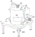
Fig. 1 is a schematic view of the overall structure of the present invention;
FIG. 2 is a schematic view of the base structure of the present invention;
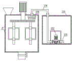
FIG. 3 is a schematic view of the water injection structure of the present invention;
FIG. 4 is a schematic view of the fixing base of the present invention;
fig. 5 is a schematic view of the packing structure of the present invention.
In the figure: 1. a base; 11. mounting grooves; 12. a support bar; 13. a stable structure; 131. a fixing plate; 132. a threaded rod; 133. an arc-shaped plate; 14. an auxiliary plate; 2. a mixing tank; 21. a feed inlet; 22. a fixed seat; 221. a drive motor; 222. a driving gear; 223. a driven structure; 2231. a driven gear; 2232. a connecting rod; 2233. a mixing member; 23. a water injection structure; 231. a water tank; 232. a water pump; 233. a water pumping pipe; 234. a water injection pipe; 235. a spray head; 24. a filler structure; 241. a delivery pump; 242. a connecting plate; 243. a charging hopper; 244. a delivery pipe; 25. an observation window; 26. a discharging pipe; 261. a valve; 27. and (4) no adhesion layer.
Detailed Description
The technical solutions in the embodiments of the present invention will be described clearly and completely with reference to the accompanying drawings in the embodiments of the present invention, and it is obvious that the described embodiments are only some embodiments of the present invention, not all embodiments. Based on the embodiments in the present invention, all other embodiments obtained by a person skilled in the art without creative work belong to the protection scope of the present invention.
Referring to fig. 1, a stably supported mixing device for concrete processing includes a base 1 and a mixing tank 2, wherein the mixing tank 2 is disposed at an upper end of the base 1, the base 1 includes a mounting groove 11, a support rod 12, a stabilizing structure 13 and an auxiliary plate 14, the mounting groove 11 is processed on an upper surface of the base 1, the support rod 12 is disposed at a lower end of the base 1, the stabilizing structure 13 is disposed at an upper end of the base 1, and the auxiliary plate 14 is fixedly mounted at one side of the base 1; the mixing tank 2 comprises a feed inlet 21, a fixed seat 22, a water injection structure 23, a filling structure 24, an observation window 25, a blanking pipe 26 and a non-stick layer 27, wherein the feed inlet 21 is arranged at the upper end of the mixing tank 2, the fixed seat 22 is arranged at one side of the feed inlet 21, the water injection structure 23 is arranged at one side of the mixing tank 2 and is arranged at the upper end of the auxiliary plate 14, the filling structure 24 is arranged at the upper end of the base 1, the observation window 25 is arranged on the surface of the mixing tank 2, the blanking pipe 26 is arranged at the lower end of the mixing tank 2, and the non-stick layer 27 is arranged on the inner wall of the mixing tank 2; a valve 261 is provided at one side of the down pipe 26.
Referring to fig. 2, the fixing structure 13 includes a fixing plate 131, a threaded rod 132 and an arc plate 133, the fixing plate 131 is fixedly installed at the upper end of the base 1, the threaded rod 132 penetrates through the fixing plate 131, and the other end of the threaded rod 132 is movably connected with the arc plate 133; two groups of stabilizing structures 13 are arranged, and the two groups of stabilizing structures 13 are symmetrically distributed about the longitudinal center line of the base 1; operating personnel can install blending tank 2 in the inboard of mounting groove 11, is provided with fixed plate 131 at base 1's upper surface simultaneously, and threaded rod 132 runs through fixed plate 131, and with arc 133 swing joint, through rotating threaded rod 132 for arc 133 is close to blending tank 2's surface, and when two sets of arcs 133 hug closely the outer wall of blending tank 2, the stall makes blending tank 2 fixed mounting in base 1's upper end, and is stable effectual.
Referring to fig. 3 and 4, the fixing base 22 includes a driving motor 221, a driving gear 222 and a driven structure 223, the driving motor 221 is disposed at the upper end of the fixing base 22, an output end of the driving motor 221 is connected to the driving gear 222, and the driven structure 223 is disposed at one side of the driving gear 222; the driven structure 223 includes a driven gear 2231, a connecting rod 2232 and a mixing piece 2233, the driven gear 2231 is disposed at one side of the driving gear 222, and the driven gear 2231 is engaged with the driving gear 222, the connecting rod 2232 is disposed at a lower end of the driven gear 2231, and the mixing piece 2233 is disposed at one side of the connecting rod 2232; the water injection structure 23 comprises a water tank 231, a water pump 232, a water pumping pipe 233, a water injection pipe 234 and a spray head 235, wherein the water tank 231 is arranged at the upper end of the auxiliary plate 14, the water pump 232 is arranged inside the water tank 231, one end of the water pump 232 is connected with the water pumping pipe 233, the other end of the water pump 232 is connected with the water injection pipe 234, and the spray head 235 is arranged at one side of the water injection pipe 234 and inside the mixing tank 2; driving motor 221 drive driving gear 222 rotates, and driving gear 222 meshes with driven gear 2231 mutually, make driven gear 2231 drive connecting rod 2232 and mixing part 2233 and rotate, be convenient for mix the raw materials, be provided with water tank 231 in one side of blending tank 2 simultaneously, utilize water pump 232 to inject into blending tank 2 through water injection pipe 234 and shower nozzle 235 with the water in the water tank 231 in, can be for the concrete supplementary moisture, prevent that moisture lacks and lead to the concrete caking.
Referring to fig. 5, the filling structure 24 includes a delivery pump 241, a connecting plate 242, a feeding funnel 243 and a delivery pipe 244, the delivery pump 241 is disposed at one side of the mixing tank 2, the delivery pump 241 and the base 1 are fixedly mounted through the connecting plate 242, the feeding funnel 243 is disposed at the upper end of the delivery pump 241, the delivery pipe 244 is disposed at one side of the delivery pump 241, and the other end of the delivery pipe 244 is connected to the mixing tank 2; the operating personnel can add the retarder into feed hopper 243, start delivery pump 241 for in the retarder can enter into blending tank 2, the extension concrete use that condenses, conveniently uses.
In summary, the following steps: the utility model provides a support stable mixing arrangement for concrete processing, including base 1 and mixing tank 2, mixing tank 2 sets up in the upper end of base 1, upper surface processing at base 1 has mounting groove 11, operating personnel can install mixing tank 2 in the inboard of mounting groove 11, be provided with fixed plate 131 on the upper surface of base 1 simultaneously, threaded rod 132 runs through fixed plate 131, and with arc 133 swing joint, through rotating threaded rod 132, make arc 133 close to mixing tank 2's surface, when two sets of arcs 133 hug closely the outer wall of mixing tank 2, stop rotating, make mixing tank 2 fixedly mounted in the upper end of base 1, stable effectual, mixing tank 2's upper end is provided with feed inlet 21, the raw materials can be put into mixing tank 2's inside from feed inlet 21, driving motor 221 sets up in the upper end of fixing base 22, driving motor 221's output is connected with driving gear 222, driving motor 221 drive driving gear 222 rotates, and driving gear 222 meshes with driven gear 2231 mutually, make driven gear 2231 drive connecting rod 2232 and mixing element 2233 rotate, be convenient for mix the raw materials, be provided with water tank 231 in one side of blending tank 2 simultaneously, utilize water pump 232 to inject into blending tank 2 through water injection pipe 234 and shower nozzle 235 with the water in the water tank 231, can supply moisture for the concrete, prevent that moisture lacks and lead to the concrete caking, be provided with delivery pump 241 in the upper end of base 1, delivery pump 241 passes through connecting plate 242 fixed mounting with base 1, operating personnel can add the feed hopper 243 in with the retarder, and delivery pump 241 is connected through conveying pipeline 244 with blending tank 2, start delivery pump 241, make the retarder can enter into blending tank 2 in, the extension concrete condenses the use, conveniently use.
It is noted that, herein, relational terms such as first and second, and the like may be used solely to distinguish one entity or action from another entity or action without necessarily requiring or implying any actual such relationship or order between such entities or actions. Also, the terms "comprises," "comprising," or any other variation thereof, are intended to cover a non-exclusive inclusion, such that a process, method, article, or apparatus that comprises a list of elements does not include only those elements but may include other elements not expressly listed or inherent to such process, method, article, or apparatus.
Although embodiments of the present invention have been shown and described, it will be appreciated by those skilled in the art that changes, modifications, substitutions and alterations can be made in these embodiments without departing from the principles and spirit of the invention, the scope of which is defined in the appended claims and their equivalents.
Claims (8)
1. The utility model provides a support stable mixing arrangement for concrete processing, includes base (1) and blending tank (2), and blending tank (2) set up the upper end at base (1), its characterized in that: the base (1) comprises a mounting groove (11), a supporting rod (12), a stabilizing structure (13) and an auxiliary plate (14), wherein the mounting groove (11) is processed on the upper surface of the base (1), the supporting rod (12) is arranged at the lower end of the base (1), the stabilizing structure (13) is arranged at the upper end of the base (1), and the auxiliary plate (14) is fixedly arranged on one side of the base (1);
mixing tank (2) includes feed inlet (21), fixing base (22), water injection structure (23), filler structure (24), observation window (25), unloading pipe (26) and non-stick layer (27), feed inlet (21) set up the upper end in mixing tank (2), fixing base (22) set up the one side in feed inlet (21), water injection structure (23) set up the one side in mixing tank (2), and set up the upper end in accessory plate (14), filler structure (24) set up the upper end in base (1), observation window (25) set up the surface in mixing tank (2), unloading pipe (26) set up the lower extreme in mixing tank (2), non-stick layer (27) set up the inner wall in mixing tank (2).
2. A mixing apparatus for processing concrete that is stable in support according to claim 1, wherein: firm structure (13) are including fixed plate (131), threaded rod (132) and arc (133), fixed plate (131) fixed mounting in the upper end of base (1), and threaded rod (132) run through fixed plate (131), and the other end and arc (133) swing joint of threaded rod (132).
3. A mixing apparatus for processing concrete that is stable in support according to claim 1, wherein: the fixing seat (22) comprises a driving motor (221), a driving gear (222) and a driven structure (223), the driving motor (221) is arranged at the upper end of the fixing seat (22), the output end of the driving motor (221) is connected with the driving gear (222), and the driven structure (223) is arranged on one side of the driving gear (222).
4. A mixing apparatus for processing concrete that is stable in support according to claim 3, wherein: driven structure (223) include driven gear (2231), connecting rod (2232) and mixing piece (2233), and driven gear (2231) sets up the one side at driving gear (222), and driven gear (2231) meshes with driving gear (222) mutually, and connecting rod (2232) set up the lower extreme at driven gear (2231), and mixing piece (2233) sets up the one side at connecting rod (2232).
5. A mixing apparatus for processing concrete that is stable in support according to claim 1, wherein: the water injection structure (23) comprises a water tank (231), a water pump (232), a water pumping pipe (233), a water injection pipe (234) and a spray head (235), the water tank (231) is arranged at the upper end of the auxiliary plate (14), the water pump (232) is arranged inside the water tank (231), one end of the water pump (232) is connected with the water pumping pipe (233), the other end of the water pump is connected with the water injection pipe (234), and the spray head (235) is arranged on one side of the water injection pipe (234) and is arranged inside the mixing tank (2).
6. A mixing apparatus for processing concrete that is stable in support according to claim 1, wherein: packing structure (24) include delivery pump (241), connecting plate (242), feed hopper (243) and conveying pipeline (244), delivery pump (241) set up the one side at blending tank (2), delivery pump (241) pass through connecting plate (242) fixed mounting with base (1), feed hopper (243) set up the upper end at delivery pump (241), conveying pipeline (244) set up the one side at delivery pump (241), and the other end of conveying pipeline (244) is connected with blending tank (2).
7. A mixing apparatus for processing concrete that is stable in support according to claim 1, wherein: and a valve (261) is arranged on one side of the blanking pipe (26).
8. A mixing apparatus for processing concrete that is stable in support according to claim 1, wherein: the fixing structures (13) are arranged in two groups, and the fixing structures (13) in the two groups are symmetrically distributed around the longitudinal center line of the base (1).
Priority Applications (1)
| Application Number | Priority Date | Filing Date | Title |
|---|---|---|---|
| CN202022342066.2U CN214110901U (en) | 2020-10-20 | 2020-10-20 | Support stable mixing arrangement for concrete processing |
Applications Claiming Priority (1)
| Application Number | Priority Date | Filing Date | Title |
|---|---|---|---|
| CN202022342066.2U CN214110901U (en) | 2020-10-20 | 2020-10-20 | Support stable mixing arrangement for concrete processing |
Publications (1)
| Publication Number | Publication Date |
|---|---|
| CN214110901U true CN214110901U (en) | 2021-09-03 |
Family
ID=77501115
Family Applications (1)
| Application Number | Title | Priority Date | Filing Date |
|---|---|---|---|
| CN202022342066.2U Expired - Fee Related CN214110901U (en) | 2020-10-20 | 2020-10-20 | Support stable mixing arrangement for concrete processing |
Country Status (1)
| Country | Link |
|---|---|
| CN (1) | CN214110901U (en) |
-
2020
- 2020-10-20 CN CN202022342066.2U patent/CN214110901U/en not_active Expired - Fee Related
Similar Documents
| Publication | Publication Date | Title |
|---|---|---|
| JP2019524499A (en) | Manufacturing method of fiber reinforced cementitious slurry using multistage continuous mixer | |
| KR100924651B1 (en) | Portable mortar construction device | |
| CN111300643B (en) | Layered multi-stage type mixed material treatment process for concrete mortar preparation | |
| CN111873179A (en) | A preparation facilities for municipal concrete | |
| CN104942998B (en) | A kind of green concrete construction equipment and construction method | |
| CN109605574A (en) | A kind of blender of automatic feeding-discharging for building | |
| CN219445579U (en) | Road bridge construction cement dosing unit | |
| CN215702862U (en) | Mechanical stirring device for preventing commercial concrete from solidifying | |
| CN213055360U (en) | Concrete automatic blending stirring injection system | |
| CN202498640U (en) | Movable premixed dry-mixed mortar production device | |
| KR20160104376A (en) | Apparatus for mixing resin and mortar | |
| CN216157686U (en) | Electric power tunnel section of jurisdiction hand hole plugging device | |
| CN214739967U (en) | Concrete conveying device for construction site | |
| CN212764151U (en) | A batching agitating unit for production of artificial quartzite panel | |
| CN211891398U (en) | Anti-blocking concrete powder storage hopper | |
| CN210239079U (en) | Make wall body mixed spraying equipment for building material | |
| CN212352440U (en) | Premixing device for concrete stirring | |
| CN223442522U (en) | Concrete proportioning machine for concrete production | |
| CN218365610U (en) | Mixing arrangement is used in bonding mortar production | |
| CN211030671U (en) | Concrete mixer with equal amount of direct injection device | |
| CN216266821U (en) | Concrete material's storage device | |
| CN214819669U (en) | Stirrer device for concrete production | |
| CN214020343U (en) | Production equipment for high-strength impervious concrete inorganic waterproof additive | |
| CN210594350U (en) | Concrete automatic telescopic lowering hopper | |
| CN222553878U (en) | Cement raw material batching device |
Legal Events
| Date | Code | Title | Description |
|---|---|---|---|
| GR01 | Patent grant | ||
| GR01 | Patent grant | ||
| CF01 | Termination of patent right due to non-payment of annual fee |
Granted publication date: 20210903 |
|
| CF01 | Termination of patent right due to non-payment of annual fee |