Air duct system of integrated stove
Technical Field
The utility model relates to a field of integrated kitchen, in particular to integrated kitchen ducting system.
Background
The traditional integrated cooker is generally provided with an air outlet channel with a left air outlet and a right air outlet, and the left air outlet and the right air outlet are oppositely arranged left and right, so that when air is discharged left and right, the air directions in the air channel are seriously crossed, and the air quantity and the air pressure of the air outlets on the left side and the right side are greatly different, so that the user experience is influenced; meanwhile, a device capable of adjusting the air outlet direction is arranged in an air duct system of a part of existing integrated stove products, for example, a document with the patent number of CN201920915976.X discloses an air duct cylinder of an integrated stove with a steering device, the operation is relatively troublesome, and great inconvenience is brought to installation and maintenance work.
SUMMERY OF THE UTILITY MODEL
An object of the utility model is to provide an integrated kitchen ducting system to solve one or more technical problem that exist among the prior art, provide a profitable selection or create the condition at least.
The technical scheme adopted for solving the technical problems is as follows:
an integrated stove ducting system, comprising: the air duct shell comprises a first air duct extending leftwards and rightwards and a second air duct extending upwards and downwards, an air passing opening is formed in the upper side of the right end of the first air duct, the lower end of the second air duct is connected with the air passing opening, a left air outlet is formed in the left end of the first air duct, a right air outlet is formed in the right side wall of the second air duct, and an air inlet is formed in the upper portion of the second air duct; the air inlet blocking cover is detachably blocked on the left air outlet or the right air outlet; the air deflector is detachably plugged and mounted on the air passing opening; the fan assembly is provided with a smoke inlet and a smoke outlet, and the smoke outlet is connected with the air inlet.
The utility model has the advantages that: when only the left air outlet is needed to discharge air, the air outlet blocking cover is arranged at the right air outlet to block the right air outlet; when only need in the air outlet of right side air outlet, wind gap blanking cover installs in left air outlet, shutoff left air outlet, and the aviation baffle is installed in crossing the wind gap, and the shutoff crosses the wind gap to can switch the direction of air-out in a flexible way, easy to assemble, dismantlement again, and because left air outlet and right air outlet put on different horizontal planes, thereby can avoid the inside phenomenon that the wind direction cross reduces amount of wind, wind pressure of appearing of wind channel like this and take place.
As a further improvement of the above technical solution, the right edge of the air deflector is connected with a fixing frame in a bent manner, the fixing frame is perpendicular to the air deflector, the fixing frame has a shape and size corresponding to the left air outlet and the right air outlet, and the air deflector can be detachably connected with the right air outlet through the fixing frame.
When the air passing opening needs to be blocked, the fixing frame is connected with the right air outlet, and the air deflector can seal the air passing opening; when the air outlet of the left air outlet is needed, the fixing frame is connected with the left air outlet, and the air deflector is tightly attached to the side wall of the first air channel at the moment, so that the air outlet is influenced, and the air outlet can be effectively stored and matched for use.
As a further improvement of the above technical scheme, the left side wall of the second air duct is inclined from top to bottom to the left, and the air inlet is arranged on the left side wall of the second air duct.
The flue gas that collects through the fan subassembly gets into from the air intake, can make the slope of flue gas get into in the second wind channel, reduces wind and makes an uproar.
As a further improvement of the technical scheme, the integrated stove air duct system further comprises an air outlet connector, and the air outlet connector can be detachably connected with the outer side of the right air outlet or the outer side of the left air outlet. The air outlet joint is mainly convenient for connect outside tobacco pipe, and when the right air outlet was out wind, the air outlet was connected with the right air outlet, and when the left air outlet was out wind, the air outlet was connected with the left air outlet.
As a further improvement of the technical scheme, the fan assembly comprises a volute, a wind wheel and a motor, wherein the wind wheel and the motor are installed in the volute, and the smoke inlet and the smoke outlet are respectively arranged on the volute.
As a further improvement of the technical scheme, mounting screw holes are formed in the peripheries of the left air outlet and the right air outlet.
The air inlet blocking cover, the air outlet joint and the fixing frame can be connected with the mounting screw holes in the left air outlet and the right air outlet through bolts, so that air leakage is avoided in the using process.
As a further improvement of the technical scheme, the bottom of the right end of the first air duct is provided with an arc chamfer. The arc chamfer is more favorable for the circulation of flue gas, has avoided the greasy dirt accumulation simultaneously.
Drawings
The present invention will be further explained with reference to the drawings and examples;
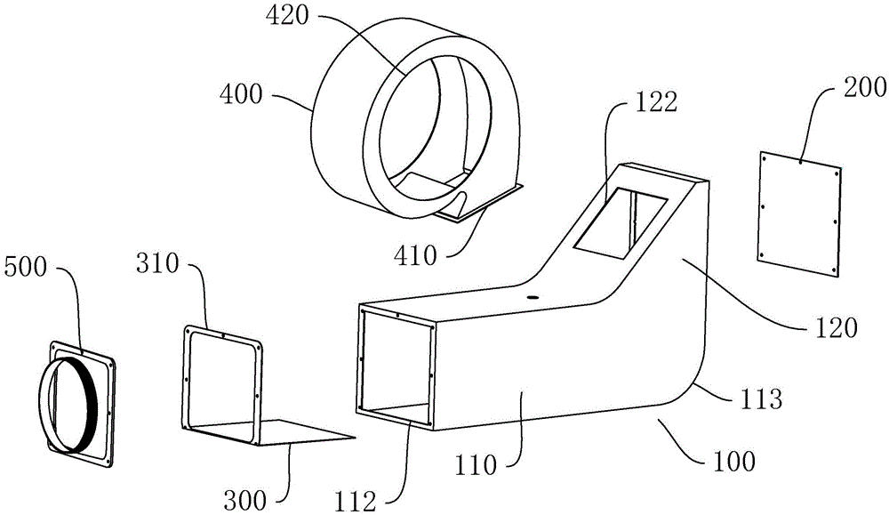
fig. 1 is an exploded view of an embodiment of an integrated oven duct system provided by the present invention;
fig. 2 is a schematic structural diagram of the air duct system of the integrated stove according to an embodiment of the present invention when the air is discharged from the right air outlet;
fig. 3 is a schematic structural view of the right air outlet of the integrated oven duct system according to the embodiment of the present invention;
fig. 4 is a schematic view of an internal structure of the right air outlet of the embodiment of the integrated oven duct system provided by the present invention when air is discharged;
fig. 5 is a first schematic structural view of the air duct system of the integrated stove according to the embodiment of the present invention when the air exits from the left air outlet;
fig. 6 is a schematic structural view of the air duct system of the integrated stove according to the embodiment of the present invention when the air is discharged from the left air outlet;
fig. 7 is a schematic view of an internal structure of the left air outlet of the integrated oven duct system according to an embodiment of the present invention.
Detailed Description
This section will describe in detail the embodiments of the present invention, preferred embodiments of the present invention are shown in the attached drawings, which are used to supplement the description of the text part of the specification with figures, so that one can intuitively and vividly understand each technical feature and the whole technical solution of the present invention, but they cannot be understood as the limitation of the protection scope of the present invention.
In the description of the present invention, it should be understood that the orientation or positional relationship indicated with respect to the orientation description, such as up, down, front, rear, left, right, etc., is based on the orientation or positional relationship shown in the drawings, and is only for convenience of description and simplification of description, and does not indicate or imply that the device or element referred to must have a specific orientation, be constructed and operated in a specific orientation, and thus, should not be construed as limiting the present invention.
In the description of the present invention, if words such as "a plurality" are used, the meaning is one or more, the meaning of a plurality of words is two or more, and the meaning of more than, less than, more than, etc. is understood as not including the number, and the meaning of more than, less than, more than, etc. is understood as including the number.
In the description of the present invention, unless there is an explicit limitation, the words such as setting, installation, connection, etc. should be understood in a broad sense, and those skilled in the art can reasonably determine the specific meanings of the above words in combination with the specific contents of the technical solution.
Referring to fig. 1 to 7, the integrated stove duct system of the present invention comprises the following embodiments:
the air duct system of the integrated stove of the embodiment includes an air duct shell 100, an air inlet blocking cover 200, an air deflector 300 and a fan assembly, wherein the air duct shell 100 includes a first air duct 110 extending left and right and a second air duct 120 extending up and down, an air inlet 111 is arranged on the upper side of the right end of the first air duct 110, the lower end of the second air duct 120 is connected with the air inlet 111, a left air outlet 112 is arranged at the left end of the first air duct 110, a right air outlet 121 is arranged on the right side wall of the second air duct 120, and an air inlet 122 is arranged on the upper portion of the second air duct 120.
The fan assembly includes a volute 400, a wind wheel and a motor installed in the volute 400, the volute 400 is provided with a smoke inlet 420 and a smoke outlet 410, and the smoke outlet 410 is connected with the air inlet 122.
The air inlet blocking cover 200 is detachably blocked on the left air outlet 112 or the right air outlet 121; the air deflector 300 is detachably plugged and mounted on the air vent 111, specifically: the right edge of the air deflector 300 is connected with a fixing frame 310 in a bending manner, the fixing frame 310 is vertically arranged with the air deflector 300, the shape and size of the fixing frame 310 correspond to the left air outlet 112 and the right air outlet 121, and the air deflector 300 can be detachably connected with the right air outlet 121 or the left air outlet 112 through the fixing frame 310.
When only the left air outlet 112 is needed to discharge air, the air outlet blocking cover 200 is installed at the right air outlet 121 to block the right air outlet 121, the fixing frame 310 is connected with the left air outlet 112, at this time, the air deflector 300 is tightly attached to the side wall of the first air duct 110, the air discharge is affected, the effective storage and matching use can be achieved, smoke in the machine enters the second air duct 120 through the air inlet 122 after being collected uniformly through the volute 400, and then is discharged from the left air outlet 112 on the first air duct 110; when only the right air outlet 121 needs to be used for air outlet, the air inlet blocking cover 200 is installed on the left air outlet 112 to block the left air outlet 112, the fixing frame 310 is connected with the right air outlet 121, at this time, the air deflector 300 can be used for sealing the air passing opening 111 to block the air passing opening 111, smoke in the machine enters the second air channel 120 through the air inlet 122 after being collected uniformly through the volute 400, the smoke is beaten on the air deflector 300 to change the direction, and the smoke is discharged from the right air outlet 121. Therefore, the direction of air outlet can be flexibly switched, the installation and the disassembly are convenient, and the left air outlet 112 and the right air outlet 121 are arranged on different horizontal planes, so that the phenomenon that the wind direction inside the air duct is crossed to reduce the air volume and the air pressure can be avoided.
Further, the left side wall of the second air duct 120 is inclined from top to bottom to the left, the air inlet 122 is arranged on the left side wall of the second air duct 120, and the flue gas collected by the fan assembly enters from the air inlet 122, so that the flue gas can be inclined to enter the second air duct 120, and the wind noise is reduced.
In addition, integrated kitchen air duct system still includes air-out and connects 500, air-out connects 500 can dismantle with the outside of right air outlet 121 or left air outlet 112 and is connected. The air outlet connector 500 is mainly convenient for connecting an external smoke tube, when the right air outlet 121 is exhausted, the air outlet connector 500 is connected with the right air outlet 121, and when the left air outlet 112 is exhausted, the air outlet connector 500 is connected with the left air outlet 112.
Furthermore, installation screw holes are formed in the peripheries of the left air outlet 112 and the right air outlet 121, and the air outlet blocking cover 200, the air outlet connector 500 and the fixing frame 310 can be connected with the installation screw holes in the left air outlet 112 and the right air outlet 121 through bolts, so that air leakage is avoided in the using process.
Meanwhile, the bottom of the right end of the first air duct 110 is provided with an arc chamfer 113. The arc chamfer 113 is more favorable for flue gas circulation and avoids oil stain accumulation.
While the preferred embodiments of the present invention have been described in detail, it will be understood by those skilled in the art that the invention is not limited to the details of the embodiments shown, but is capable of various modifications and substitutions without departing from the spirit of the invention.