CN214310954U - Diffusion plate with supporting structure - Google Patents
Diffusion plate with supporting structure Download PDFInfo
- Publication number
- CN214310954U CN214310954U CN202120536518.2U CN202120536518U CN214310954U CN 214310954 U CN214310954 U CN 214310954U CN 202120536518 U CN202120536518 U CN 202120536518U CN 214310954 U CN214310954 U CN 214310954U
- Authority
- CN
- China
- Prior art keywords
- plate
- spring
- supporting
- fixedly connected
- diffuser plate
- Prior art date
- Legal status (The legal status is an assumption and is not a legal conclusion. Google has not performed a legal analysis and makes no representation as to the accuracy of the status listed.)
- Expired - Fee Related
Links
- 238000009792 diffusion process Methods 0.000 title claims description 27
- 230000007246 mechanism Effects 0.000 claims abstract description 9
- 230000000149 penetrating effect Effects 0.000 claims description 5
- 230000006978 adaptation Effects 0.000 claims description 3
- 238000000034 method Methods 0.000 abstract description 11
- 230000009471 action Effects 0.000 abstract description 10
- 230000000694 effects Effects 0.000 abstract description 8
- 230000008569 process Effects 0.000 abstract description 7
- 230000007774 longterm Effects 0.000 abstract description 6
- 230000035939 shock Effects 0.000 abstract description 4
- 230000003139 buffering effect Effects 0.000 description 6
- 238000013016 damping Methods 0.000 description 2
- 239000000463 material Substances 0.000 description 2
- 230000004075 alteration Effects 0.000 description 1
- 230000009286 beneficial effect Effects 0.000 description 1
- 238000006243 chemical reaction Methods 0.000 description 1
- 239000003086 colorant Substances 0.000 description 1
- 238000006073 displacement reaction Methods 0.000 description 1
- 230000002349 favourable effect Effects 0.000 description 1
- 238000005286 illumination Methods 0.000 description 1
- 238000003384 imaging method Methods 0.000 description 1
- 239000004973 liquid crystal related substance Substances 0.000 description 1
- 230000004048 modification Effects 0.000 description 1
- 238000012986 modification Methods 0.000 description 1
- 230000003287 optical effect Effects 0.000 description 1
- 229920003229 poly(methyl methacrylate) Polymers 0.000 description 1
- 239000004926 polymethyl methacrylate Substances 0.000 description 1
- 239000000126 substance Substances 0.000 description 1
- 238000006467 substitution reaction Methods 0.000 description 1
Images




Landscapes
- Vibration Prevention Devices (AREA)
Abstract
The utility model discloses a diffuser plate with bearing structure, supporting mechanism includes first backup pad and second backup pad, the first cardboard of top fixedly connected with of first backup pad, the top fixedly connected with second cardboard of second backup pad, the first spring of one side fixedly connected with of first backup pad, one side fixedly connected with second spring of second backup pad, the utility model relates to a diffuser plate technical field. This diffuser plate with bearing structure, when receiving the exogenic action, the diffuser plate body can make first spring and second spring atress deformation to cavity internal motion, can offset partly vibrations to the realization is cushioned the diffuser plate body, has solved current diffuser plate simple structure, when supporting the diffuser plate, often all is hard contact, in long-term support process, it is relatively poor to cushion the shock attenuation effect, causes the problem of the damage of diffuser plate body easily.
Description
Technical Field
The utility model relates to a diffuser plate technical field specifically is a diffuser plate with bearing structure.
Background
The light diffusion plate is characterized in that through chemical or physical means, when light meets two media with different refractive indexes in the traveling path, the physical phenomena of refraction, reflection and scattering are generated, inorganic or organic light diffusants are added into base materials such as PMMA, PC, PS, PP and the like, or the light is artificially adjusted through array arrangement of micro-feature structures on the surface of the base materials, so that the light is refracted, reflected and scattered in different directions, the traveling path of the light is changed, the effect of optical diffusion is generated by filling and dispersing colors of incident light, and the light diffusion plate is widely applied to liquid crystal display, LED illumination and imaging display systems.
In traditional straight following formula backlight unit, the diffuser plate supports with the center all around, arranges the lamp source top in, and the diffuser plate is thin and has great space with the light source, in order to prevent sunken and influence the module picture in the middle of the diffuser plate, need set up the diffuser plate support in the middle of the diffuser plate and support the diffuser plate, current diffuser plate simple structure, when supporting the diffuser plate, often all be hard contact, in long-term support process, the buffering shock attenuation effect is relatively poor, causes the damage of diffuser plate body easily, consequently, the utility model provides a diffuser plate with bearing structure to solve the problem that the aforesaid mentioned.
SUMMERY OF THE UTILITY MODEL
The utility model provides a not enough to prior art, the utility model provides a diffuser plate with bearing structure has solved current diffuser plate simple structure, when supporting the diffuser plate, often all is hard contact, and long-term support in-process, buffering shock attenuation effect is relatively poor, causes the problem of the damage of diffuser plate body easily.
In order to achieve the above purpose, the utility model discloses a following technical scheme realizes: the diffusion plate with the supporting structure comprises a diffusion plate body and a fixing plate, wherein a groove is formed in the front face of the fixing plate in a penetrating mode, and a supporting mechanism is arranged on the fixing plate.
The supporting mechanism comprises a first supporting plate and a second supporting plate, a first clamping plate is fixedly connected to the top of the first supporting plate, a second clamping plate is fixedly connected to the top of the second supporting plate, a first spring is fixedly connected to one side of the first supporting plate, and a second spring is fixedly connected to one side of the second supporting plate.
Preferably, the opposite side setting of first backup pad is the inclined plane, one side of first backup pad is run through and is seted up first spout, the opposite side setting of second backup pad is the inclined plane, one side of second backup pad is run through and is seted up the second spout.
Preferably, the top of fixed plate has been seted up and has been led to the groove, lead to and communicate between groove and the recess, the cavity has been seted up to the inside of fixed plate, the inside fixedly connected with bracing piece of cavity, the surface of bracing piece respectively with the inside looks adaptation of first spout and second spout.
Preferably, the tops of the first clamping plate and the second clamping plate are in sliding connection with the top of the cavity wall, and two sides of the diffusion plate body are in contact with one side, opposite to the first clamping plate and the second clamping plate, of the diffusion plate body respectively.
Preferably, one end of the first spring is fixedly connected with one side of the cavity wall of the cavity, and one end of the second spring is fixedly connected with the other side of the cavity wall of the cavity.
Preferably, the first spring and the second spring are sleeved on the outer surface of the supporting rod, and the bottoms of the first supporting plate and the second supporting plate are connected with the bottom of the cavity wall in a sliding mode.
Advantageous effects
The utility model provides a diffuser plate with bearing structure. Compared with the prior art, the method has the following beneficial effects:
(1) the diffusion plate with the supporting structure comprises a first supporting plate and a second supporting plate on a supporting mechanism, wherein a first clamping plate is fixedly connected to the top of the first supporting plate, a second clamping plate is fixedly connected to the top of the second supporting plate, a first spring is fixedly connected to one side of the first supporting plate, a second spring is fixedly connected to one side of the second supporting plate, and when the diffusion plate is applied with external force, the diffusion plate body moves towards the inside of a cavity to enable the first spring and the second spring to be stressed and deformed and offset part of vibration, so that the diffusion plate body is buffered, the problems that the existing diffusion plate is simple in structure, hard contact is frequently caused when the diffusion plate is supported, and the buffering and damping effects are poor in the long-term supporting process are solved, easily causing damage to the diffuser plate body.
(2) This diffuser plate with bearing structure through the cavity has been seted up in the inside at the fixed plate, and the inside fixedly connected with bracing piece of cavity, the surface of bracing piece respectively with the inside looks adaptation of first spout and second spout, use through the cooperation of first spout, second spout and bracing piece, when first backup pad and second backup pad move, be favorable to carrying out limiting displacement to first backup pad and second backup pad.
Drawings
Fig. 1 is a perspective view of the present invention;
fig. 2 is a perspective view of the fixing plate of the present invention;
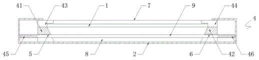
FIG. 3 is a front view of the internal structure of the present invention;
fig. 4 is a perspective view of the first support plate, the second support plate, the first clamping plate and the second clamping plate of the present invention;
fig. 5 is a partially enlarged view of a portion a in fig. 2 according to the present invention.
In the figure: the novel diffusion plate comprises a diffusion plate body 1, a fixing plate 2, a groove 3, a supporting mechanism 4, a first supporting plate 41, a second supporting plate 42, a first clamping plate 43, a second clamping plate 44, a first spring 45, a second spring 46, a first sliding groove 5, a second sliding groove 6, a through groove 7, a cavity 8 and a supporting rod 9.
Detailed Description
The technical solutions in the embodiments of the present invention will be described clearly and completely with reference to the accompanying drawings in the embodiments of the present invention, and it is obvious that the described embodiments are only some embodiments of the present invention, not all embodiments. Based on the embodiments in the present invention, all other embodiments obtained by a person skilled in the art without creative work belong to the protection scope of the present invention.
Referring to fig. 1-5, the present invention provides a technical solution: a diffusion plate with a supporting structure comprises a diffusion plate body 1 and a fixing plate 2, wherein a through groove 7 is formed in the top of the fixing plate 2, the through groove 7 is communicated with a groove 3, a cavity 8 is formed in the fixing plate 2, a supporting rod 9 is fixedly connected to the inside of the cavity 8, the outer surface of the supporting rod 9 is respectively matched with the insides of a first sliding groove 5 and a second sliding groove 6, the first sliding groove 5, the second sliding groove 6 and the supporting rod 9 are used in a matched mode, when the first supporting plate 41 and the second supporting plate 42 move, the first supporting plate 41 and the second supporting plate 42 are favorably limited, the groove 3 penetrates through the front face of the fixing plate 2, and the supporting mechanism 4 is arranged on the fixing plate 2; the supporting mechanism 4 comprises a first supporting plate 41 and a second supporting plate 42, the other side of the first supporting plate 41 is provided with an inclined plane, one side of the first supporting plate 41 is provided with a first chute 5 in a penetrating way, the other side of the second supporting plate 42 is provided with an inclined plane in a penetrating way, one side of the second supporting plate 42 is provided with a second chute 6 in a penetrating way, the top of the first supporting plate 41 is fixedly connected with a first clamping plate 43, the tops of the first clamping plate 43 and the second clamping plate 44 are both in sliding connection with the top of the cavity wall of the cavity 8, both sides of the diffusion plate body 1 are respectively in contact with the opposite sides of the first clamping plate 43 and the second clamping plate 44, the top of the second supporting plate 42 is fixedly connected with a second clamping plate 44, one side of the first supporting plate 41 is fixedly connected with a first spring 45, the first spring 45 and the second spring 46 are both sleeved on the outer surface of the supporting rod 9, the bottoms of the first supporting plate 41 and the second supporting plate 42 are both in sliding connection with the bottom of the cavity 8, one end of first spring 45 and one side fixed connection on cavity 8 chamber wall, the one end of second spring 46 and the opposite side fixed connection on cavity 8 chamber wall, one side fixed connection of second backup pad 42 has second spring 46, through first backup pad 41, second backup pad 42, first cardboard 43, second cardboard 44, first spring 45 and second spring 46's cooperation is used, when receiving the exogenic action, diffuser body 1 can make first spring 45 and second spring 46 atress deformation to cavity 8 internal motion, can offset partly vibrations, thereby realize buffering diffuser body 1, the diffuser plate simple structure who has solved current diffuser plate, when supporting the diffuser plate, often all be hard contact, in long-term support process, buffering shock attenuation effect is relatively poor, cause the problem of the damage of diffuser plate body easily.
And those not described in detail in this specification are well within the skill of those in the art.
When the diffusion plate works, when external force acts on the diffusion plate body 1, the diffusion plate body 1 moves into the cavity 8 along the inclined surfaces of the first supporting plate 41 and the second supporting plate 42, and then the first supporting plate 41 and the second supporting plate 42 are pushed to slide in the cavity 8, so that the first spring 45 is under the pressure action of the first supporting plate 41, and then the first spring 45 is in a compressed state, therefore, the first spring 45 generates an elastic force action, the second spring 46 is under the pressure action of the second supporting plate 42, and then the second spring 46 is in a compressed state, therefore, the second spring 46 generates an elastic force action, under the action of force and reaction force, the diffusion plate body 1 is buffered, the problems that the existing diffusion plate is simple in structure, when the diffusion plate is supported, hard contact is often caused, and the buffering and damping effects are poor in a long-term supporting process, easily causing damage to the diffuser plate body.
It is noted that, herein, relational terms such as first and second, and the like may be used solely to distinguish one entity or action from another entity or action without necessarily requiring or implying any actual such relationship or order between such entities or actions. Also, the terms "comprises," "comprising," or any other variation thereof, are intended to cover a non-exclusive inclusion, such that a process, method, article, or apparatus that comprises a list of elements does not include only those elements but may include other elements not expressly listed or inherent to such process, method, article, or apparatus.
Although embodiments of the present invention have been shown and described, it will be appreciated by those skilled in the art that changes, modifications, substitutions and alterations can be made in these embodiments without departing from the principles and spirit of the invention, the scope of which is defined in the appended claims and their equivalents.
Claims (6)
1. A diffuser plate with bearing structure, including diffuser plate body (1) and fixed plate (2), its characterized in that: a groove (3) is formed in the front face of the fixing plate (2) in a penetrating mode, and a supporting mechanism (4) is arranged on the fixing plate (2);
the supporting mechanism (4) comprises a first supporting plate (41) and a second supporting plate (42), a first clamping plate (43) is fixedly connected to the top of the first supporting plate (41), a second clamping plate (44) is fixedly connected to the top of the second supporting plate (42), a first spring (45) is fixedly connected to one side of the first supporting plate (41), and a second spring (46) is fixedly connected to one side of the second supporting plate (42).
2. A diffuser plate having a support structure according to claim 1, wherein: the opposite side setting of first backup pad (41) is the inclined plane, one side of first backup pad (41) is run through and has been seted up first spout (5), the opposite side setting of second backup pad (42) is the inclined plane, one side of second backup pad (42) is run through and has been seted up second spout (6).
3. A diffuser plate having a support structure according to claim 1, wherein: logical groove (7) have been seted up at the top of fixed plate (2), communicate between logical groove (7) and recess (3), cavity (8) have been seted up to the inside of fixed plate (2), the inside fixedly connected with bracing piece (9) of cavity (8), the surface of bracing piece (9) respectively with the inside looks adaptation of first spout (5) and second spout (6).
4. A diffuser plate having a support structure according to claim 1, wherein: the top of the first clamping plate (43) and the top of the second clamping plate (44) are in sliding connection with the top of the cavity wall of the cavity (8), and two sides of the diffusion plate body (1) are in contact with one side, opposite to the first clamping plate (43) and the second clamping plate (44), respectively.
5. A diffuser plate having a support structure according to claim 1, wherein: one end of the first spring (45) is fixedly connected with one side of the cavity wall of the cavity (8), and one end of the second spring (46) is fixedly connected with the other side of the cavity wall of the cavity (8).
6. A diffuser plate having a support structure according to claim 1, wherein: the first spring (45) and the second spring (46) are sleeved on the outer surface of the supporting rod (9), and the bottoms of the first supporting plate (41) and the second supporting plate (42) are in sliding connection with the bottom of the cavity wall of the cavity (8).
Priority Applications (1)
| Application Number | Priority Date | Filing Date | Title |
|---|---|---|---|
| CN202120536518.2U CN214310954U (en) | 2021-03-16 | 2021-03-16 | Diffusion plate with supporting structure |
Applications Claiming Priority (1)
| Application Number | Priority Date | Filing Date | Title |
|---|---|---|---|
| CN202120536518.2U CN214310954U (en) | 2021-03-16 | 2021-03-16 | Diffusion plate with supporting structure |
Publications (1)
| Publication Number | Publication Date |
|---|---|
| CN214310954U true CN214310954U (en) | 2021-09-28 |
Family
ID=77836644
Family Applications (1)
| Application Number | Title | Priority Date | Filing Date |
|---|---|---|---|
| CN202120536518.2U Expired - Fee Related CN214310954U (en) | 2021-03-16 | 2021-03-16 | Diffusion plate with supporting structure |
Country Status (1)
| Country | Link |
|---|---|
| CN (1) | CN214310954U (en) |
-
2021
- 2021-03-16 CN CN202120536518.2U patent/CN214310954U/en not_active Expired - Fee Related
Similar Documents
| Publication | Publication Date | Title |
|---|---|---|
| KR102461160B1 (en) | Display Device | |
| TWI522690B (en) | Hybrid light guide plate and display device | |
| KR101499847B1 (en) | Light guide plate and backlight unit having the same | |
| TW200624874A (en) | Lens of variable focal length | |
| US20130033657A1 (en) | Backlight module and liquid crystal display | |
| CN103901655A (en) | Hook-face two-sided liquid crystal displayer | |
| CN219065944U (en) | Diffusion plate for backlight source of liquid crystal display screen | |
| CN109991776A (en) | Backlight unit and multi-display apparatus including backlight unit | |
| CN214310954U (en) | Diffusion plate with supporting structure | |
| KR20130116704A (en) | Backlight assembly and display apparatus having the same | |
| US20110002144A1 (en) | Integrated optical sheet and optical device having the same | |
| KR20180014299A (en) | Light guide plate holder and Planar light source device the same | |
| CN110716346B (en) | Backlight module and liquid crystal display device | |
| CN101393281A (en) | Backlight module and its prism sheet | |
| CN102878493A (en) | Backlight module | |
| CN216434602U (en) | Quantum dot diffusion plate | |
| TW201409131A (en) | Backlight module and supporting element | |
| CN218158628U (en) | Backlight module and support column, display equipment and human-computer interaction equipment thereof | |
| CN101587203A (en) | Backlight module and optic plate thereof | |
| CN100445839C (en) | Direct type backlight module | |
| CN104536201A (en) | Double-faced display and assembling method thereof | |
| US20060227548A1 (en) | Prism set and light emitting apparatus using the same | |
| US9110198B2 (en) | Backlight module | |
| CN219456684U (en) | Lamp support assembly, backlight module and display device | |
| CN216485609U (en) | An energy-saving and high-pressure-resistance diffuser plate |
Legal Events
| Date | Code | Title | Description |
|---|---|---|---|
| GR01 | Patent grant | ||
| GR01 | Patent grant | ||
| CF01 | Termination of patent right due to non-payment of annual fee | ||
| CF01 | Termination of patent right due to non-payment of annual fee |
Granted publication date: 20210928 |