CN214347300U - Hand-push type tree trunk whitewashing machine - Google Patents
Hand-push type tree trunk whitewashing machine Download PDFInfo
- Publication number
- CN214347300U CN214347300U CN202022926791.4U CN202022926791U CN214347300U CN 214347300 U CN214347300 U CN 214347300U CN 202022926791 U CN202022926791 U CN 202022926791U CN 214347300 U CN214347300 U CN 214347300U
- Authority
- CN
- China
- Prior art keywords
- arc
- mounting
- seat
- slurry
- shaped plate
- Prior art date
- Legal status (The legal status is an assumption and is not a legal conclusion. Google has not performed a legal analysis and makes no representation as to the accuracy of the status listed.)
- Expired - Fee Related
Links
Images


Landscapes
- Special Spraying Apparatus (AREA)
Abstract
The utility model relates to a municipal afforestation equipment technical field is a hand propelled trunk whitewash tree machine, and it includes handcart, installation barrel, spary device, elevating gear, defeated thick liquid device and defeated thick liquid pipeline, and the handcart front side is equipped with the installation barrel, and the installation barrel includes half a left side and half a right side, and half a left side rear portion right side and half a right side rear portion left side articulate together, and half a left side anterior right side and half a right side anterior left side detachable fixed mounting of a left side are in the same place. The utility model has reasonable and compact structure and convenient use, and is convenient for installing the cylinder body on the outer side of the trunk by arranging the left half cylinder and the right half cylinder which are fixedly installed together in a detachable way; the tree trunk is whitewashed by arranging a brush and a nozzle; through setting up elevating gear, make the spary device reciprocate along the trunk outside, have high efficiency, quick and practice thrift the characteristics of coating.
Description
Technical Field
The utility model relates to a municipal afforestation equipment technical field is a hand propelled trunk whitewash brush tree machine.
Background
Urban greening is the activity of planting plants to improve urban environment, and along with the establishment and development of nationwide civilized cities, municipal greening engineering plays an important role in improving living environment and protecting urban ecological systems. The trees are used as main planting species for municipal greening, can purify air, absorb dust, absorb carbon dioxide, release oxygen, maintain water and soil, and play an important role in improving the natural environment. However, trees are vulnerable to diseases and pests in natural environments, and in order to prevent the trees from being gnawed, damaged and frostbitten by insects, ants, diseases and the like during dormancy in winter, a white lime coating is often coated on the trunk, and the white lime coating coated on the trunk can provide a barrier to prevent germs from entering, prevent insects, kill pests, prevent cold and beautify the environment.
In the prior art, the trunk whitewashing work is generally finished by a manual whitewashing method by greening workers, but the manual whitewashing work efficiency is low, the labor intensity is high, and meanwhile, the preparation and the use of lime paint can also harm the health of operators.
Disclosure of Invention
The utility model provides a hand propelled trunk whitewash brush tree machine has overcome above-mentioned prior art not enough, and it can effectively solve current manual work and carry out the trunk whitewash and waste time and energy and the healthy problem of harmfulness.
The technical scheme of the utility model is realized through following measure: a hand-push type tree trunk whitewashing tree brushing machine comprises a trolley, an installation barrel, a spraying device, a lifting device, a pulp conveying device and a pulp conveying pipeline, wherein the installation barrel is arranged on the front side of the trolley, the installation barrel comprises a left half barrel and a right half barrel, the right side of the rear part of the left half barrel is hinged with the left side of the rear part of the right half barrel, and the right side of the front part of the left half barrel is detachably and fixedly installed with the left side of the front part of the right half barrel; the installation cylinder is internally provided with a spraying device and a lifting device which can enable the spraying device to move up and down in the installation cylinder; the rear part of the handcart is provided with a slurry conveying device, and a liquid outlet of the slurry conveying device is communicated with a liquid inlet of the spraying and brushing device through a slurry conveying pipeline.
The following are further optimization or/and improvement of the technical scheme of the utility model:
the lifting device can comprise a left mounting column, a right mounting column, an upper annular beam and a lower annular beam, the upper annular beam is arranged on the inner side of the upper end of the mounting cylinder body, the lower annular beam is arranged on the inner side of the lower end of the mounting cylinder body, the upper annular beam comprises a first arc-shaped plate and a second arc-shaped plate, the lower annular beam comprises a third arc-shaped plate and a fourth arc-shaped plate, the first arc-shaped plate and the third arc-shaped plate are both arc-shaped with right openings, the left mounting column is fixedly mounted in the middle of the first arc-shaped plate and in the middle of the third arc-shaped plate, the second arc-shaped plate and the fourth arc-shaped plate are both arc-shaped with left openings, and the right mounting column is fixedly mounted in the middle of the second arc-shaped plate and in the middle of the fourth arc-shaped plate.
The spraying and brushing device can comprise a left spraying and brushing device and a right spraying and brushing device, and the lifting device comprises a left lifting device and a right lifting device; the left lifting device comprises a driving motor, an upper mounting seat, a lower mounting seat, a driving wheel, a driven wheel, a conveying belt and a sliding block, wherein the upper mounting seat is fixedly mounted on the right side of the upper end of a left mounting column, the lower mounting seat is fixedly mounted on the right side of the lower end of the left mounting column, the upper mounting seat is provided with an upper mounting cavity which is vertically communicated and has a left opening, the driving wheel is arranged in the upper mounting cavity, the lower mounting seat is provided with a lower mounting cavity which is vertically communicated and has a left opening, the driven wheel is arranged in the lower mounting cavity, the axes of the driving wheel and the driven wheel are both arranged in the left-right direction, the conveying belt which can enable the driving wheel and the driven wheel to be connected together in a transmission mode is arranged on the outer sides of the driving wheel and the driven wheel, the driving motor is arranged in the middle of the upper side of the first arc plate, and the output shaft of the driving motor is connected with the driving wheel in a transmission mode; the outer side of the middle part of the conveyor belt is provided with a sliding block, the sliding block is provided with a sliding cavity which is communicated up and down and has a left opening, the inner side of the front part of the sliding block is fixedly arranged with the corresponding position of the front side of the conveyor belt, and the right side of the sliding block is fixedly provided with a left spraying device; the right lifting device and the left lifting device are identical in structure and are distributed in bilateral symmetry, and the right spraying and brushing device and the left spraying and brushing device are identical in structure and are distributed in bilateral symmetry.
The left spraying device can comprise a fixed seat, a spraying support, brushes, nozzles, an upper roller and a lower roller, wherein the fixed seat is Contraband-shaped with a right opening, the middle part of the right side of the fixed seat is fixedly provided with the spraying support, the spraying support is in a semicircular ring shape with the right opening, the inner side of the upper part of the spraying support is provided with at least three brushes at intervals along the circumferential direction, the inner side of the lower part of the spraying support is provided with at least three nozzles at intervals along the circumferential direction, and each nozzle is communicated with a liquid outlet of the slurry conveying device through a slurry conveying pipeline; the right side of the upper part of the fixing seat is provided with a first mounting opening with a rightward opening, an upper roller is arranged in the first mounting opening, the right side of the lower part of the fixing seat is provided with a second mounting opening with a rightward opening, and a lower roller is arranged in the second mounting opening.
The above-mentioned still can include first limit switch and second limit switch, goes up the mount pad downside and is equipped with first limit switch, and the mount pad upside is equipped with second limit switch down, and first limit switch and second limit switch all are connected with driving motor.
The left lifting device can also comprise a first guide wheel and a second guide wheel, a first guide groove is formed in the left side of the left mounting column, a second guide groove is formed in the right side of the left mounting column, two first guide wheels positioned in the first guide groove are arranged on the inner side of the left part of the sliding block at intervals from top to bottom, two second guide wheels positioned in the second guide groove are arranged on the inner side of the right part of the sliding block at intervals from top to bottom, and the axes of the first guide wheels and the second guide wheels are arranged in the front-back direction; the left side of the right mounting column is provided with a third guide groove, and the right side of the right mounting column is provided with a fourth guide groove.
The slurry conveying device can comprise a slurry storage box, a slurry conveying pump, a stirring motor, a speed reducer, a stirring shaft and stirring blades, the upper portion of the rear side of the trolley is provided with the slurry conveying pump, the lower portion of the rear side of the trolley is provided with the slurry storage box, the upper side of the storage box is provided with the speed reducer and the stirring motor, the output shaft of the stirring motor is connected with the input end of the speed reducer, the central portion of the upper side of the slurry storage box is provided with a mounting hole, the stirring shaft with the upper end located above the slurry storage box is arranged in the mounting hole, the output end of the speed reducer is connected with the upper end of the stirring shaft in a transmission mode, the stirring blades are fixedly arranged on the outer side of the lower portion of the stirring shaft, the slurry storage box is provided with a feed inlet, the front side of the lower portion of the stirring hopper is provided with a slurry outlet, the slurry outlet is communicated with the feed inlet of the slurry conveying pump through a slurry conveying pipeline, and the slurry conveying hole of the slurry conveying pump is communicated with the feed inlet of the spraying and brushing device through a slurry conveying pipeline.
The trolley can comprise a trolley frame, a hinging seat, a hinging connecting rod group, a handrail, a bottom plate, walking wheels and universal wheels, wherein the bottom plate is fixedly arranged on the front side of the lower end of the trolley frame, the mounting barrel body is arranged on the upper side of the bottom plate, the hinging seat is arranged on the trolley frame corresponding to the rear side of the upper end of the mounting barrel body, the hinging connecting rod group is arranged on the upper side of the hinging seat and is in a shape like a Chinese character 'er', the hinging connecting rod group comprises a left arc-shaped hinging rod and a right arc-shaped hinging rod which are distributed at intervals left and right, the rear end of the left arc-shaped hinging rod is hinged with the upper side of the left part of the hinging seat, the front end of the left hinging arc-shaped rod is hinged with the upper side of the rear part of the first arc-shaped plate, the rear end of the right arc-shaped hinging rod is hinged with the upper side of the right part of the hinging seat, and the front end of the right hinging arc-shaped rod is hinged with the upper side of the rear part of the third arc-shaped plate; the rear side of the upper end of the frame is fixedly provided with a handrail, the lower side of the bottom plate is provided with universal wheels, and the left side and the right side of the lower end of the frame are provided with walking wheels.
The utility model has reasonable and compact structure and convenient use, and is convenient for installing the cylinder body on the outer side of the trunk by arranging the left half cylinder and the right half cylinder which are fixedly installed together in a detachable way; the tree trunk is whitewashed by arranging a brush and a nozzle; the spraying and brushing device moves up and down along the outer side of the trunk by arranging the lifting device; through setting up annular spary device, avoid having to scribble the white use inconvenient, the spraying scope is comprehensive inadequately and the big ground paste that causes of coating spraying scope pollutes and waste etc. defect to the trunk of different thicknesses, have high efficiency, quick and practice thrift the characteristics of coating.
Drawings
Fig. 1 is a right-view structural diagram of the preferred embodiment of the present invention.
Fig. 2 is a schematic perspective view of fig. 1.
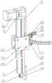
Fig. 3 is a schematic perspective sectional view of the left lifting device and the left spraying device in fig. 1.
The codes in the figures are respectively: 1 is a left half section of thick bamboo, 2 is a right half section of thick bamboo, 3 is the storage box, 4 is the defeated thick liquid pipeline, 5 is the left erection column, 6 is first arc, 7 is the second arc, 8 is the third arc, 9 is the action wheel, 10 is driving motor, 11 is the mount pad, 12 is lower mount pad, 13 is from the driving wheel, 14 is the conveyer belt, 15 is the slider, 16 is the fixing base, 17 is the spary support, 18 is the brush, 19 is the nozzle, 20 is the upper roller, 21 is the lower roller, 22 is first leading wheel, 23 is the second leading wheel, 24 is the conveying pump, 25 is left arc articulated pole, 26 is right arc articulated pole, 27 is the frame, 28 is articulated seat, 29 is the handrail, 30 is the bottom plate, 31 is the walking wheel, 32 is the universal wheel.
Detailed Description
The utility model discloses do not receive the restriction of following embodiment, can be according to the utility model discloses a technical scheme and actual conditions determine concrete implementation.
In the present invention, for convenience of description, the description of the relative position relationship of the components is described according to the layout mode of the attached drawing 1 in the specification, such as: the positional relationship of front, rear, upper, lower, left, right, etc. is determined in accordance with the layout direction of fig. 1 of the specification.
The invention will be further described with reference to the following examples and drawings:
as shown in attached figures 1, 2 and 3, the hand-push type tree trunk whitewashing machine comprises a trolley, an installation cylinder, a spraying device, a lifting device, a pulp conveying device and a pulp conveying pipeline 4, wherein the installation cylinder is arranged on the front side of the trolley and comprises a left half cylinder 1 and a right half cylinder 2, the right side of the rear part of the left half cylinder 1 is hinged with the left side of the rear part of the right half cylinder 2, and the right side of the front part of the left half cylinder 1 is detachably and fixedly installed with the left side of the front part of the right half cylinder 2; the installation cylinder is internally provided with a spraying device and a lifting device which can enable the spraying device to move up and down in the installation cylinder; the rear part of the handcart is provided with a slurry conveying device, and the liquid outlet of the slurry conveying device is communicated with the liquid inlet of the spraying and brushing device through a slurry conveying pipeline 4. In the use, when needs whitewash the operation to the trunk, the workman utilizes the hand push dolly will the utility model discloses remove near the trunk, expand half a section of thick bamboo 1 on the left and half a section of thick bamboo 2 on the right, make half a section of thick bamboo 1 on the left and half a section of thick bamboo 2 on the right and make half a section of thick bamboo 1 on the left front portion right side and half a section of thick bamboo 2 on the right front portion left side detachable fixed mounting together again after embracing the trunk, start earlier the spary device, then start elevating gear and make the spary device go up and down along the trunk outside to accomplish the trunk whitewash operation, avoid the manual work to carry out the trunk whitewash and waste time and energy and harmful healthy problem.
The hand-push type trunk whitewashing tree brushing machine can be further optimized or/and improved according to actual needs:
as shown in fig. 1, 2 and 3, the lifting device comprises a left mounting column 5, a right mounting column, an upper ring beam and a lower ring beam, the upper ring beam is arranged on the inner side of the upper end of the mounting cylinder, the lower ring beam is arranged on the inner side of the lower end of the mounting cylinder, the upper ring beam comprises a first arc-shaped plate 6 and a second arc-shaped plate 7, the lower ring beam comprises a third arc-shaped plate 8 and a fourth arc-shaped plate, the first arc-shaped plate 6 and the third arc-shaped plate 8 are both in the shape of an opening right arc, the left mounting column 5 is fixedly mounted between the middle part of the first arc-shaped plate 6 and the middle part of the third arc-shaped plate 8, the second arc-shaped plate 7 and the fourth arc-shaped plate are both in the shape of an opening left arc, and the right mounting column is fixedly mounted between the middle part of the second arc-shaped plate 7 and the middle part of the fourth arc-shaped plate. In the use process, through such setting, be convenient for elevating gear and spary device to install in the installation barrel.
As shown in fig. 1, 2 and 3, the spraying device comprises a left spraying device and a right spraying device, and the lifting device comprises a left lifting device and a right lifting device; the left lifting device comprises a driving motor 10, an upper mounting seat 11, a lower mounting seat 12, a driving wheel 9, a driven wheel 13, a conveyor belt 14 and a sliding block 15, the upper mounting seat 11 is fixedly mounted on the right side of the upper end of the left mounting column 5, the lower mounting seat 12 is fixedly mounted on the right side of the lower end of the left mounting column 5, the upper mounting seat 11 is provided with an upper mounting cavity which is vertically communicated and has a left opening, the driving wheel 9 is arranged in the upper mounting cavity, the lower mounting seat 12 is provided with a lower mounting cavity which is vertically communicated and has a left opening, the driven wheel 13 is arranged in the lower mounting cavity, the axes of the driving wheel 9 and the driven wheel 13 are arranged in the left-right direction, the conveyor belt 14 which can drive and connect the driving wheel 9 and the driven wheel 13 together is arranged outside the driving wheel 9 and the driven wheel 13, the driving motor 10 is arranged in the middle of the upper side of the first arc-shaped plate 6, and the output shaft of the driving motor 10 is in transmission connection with the driving wheel 9; a sliding block 15 is arranged on the outer side of the middle part of the conveyor belt 14, the sliding block 15 is provided with a sliding cavity which is vertically communicated and has a leftward opening, the inner side of the front part of the sliding block 15 is fixedly arranged with the corresponding position of the front side of the conveyor belt 14, and a left spraying and brushing device is fixedly arranged on the right side of the sliding block 15; the right lifting device and the left lifting device are identical in structure and are distributed in bilateral symmetry, and the right spraying and brushing device and the left spraying and brushing device are identical in structure and are distributed in bilateral symmetry. In the use process, through the arrangement, the spraying and brushing device can be enabled to be stable when ascending and descending along the left mounting column 5 and the right mounting column in the mounting cylinder, and therefore the tree trunk whitewashing operation is achieved.
As shown in fig. 1, 2 and 3, the left spraying device comprises a fixed seat 16, a spraying support 17, brushes 18, nozzles 19, an upper roller 20 and a lower roller 21, wherein the fixed seat 16 is shaped like Contraband with a rightward opening, the middle part of the right side of the fixed seat 16 is fixedly provided with the spraying support 17, the spraying support 17 is shaped like a semicircular ring with a rightward opening, the inner side of the upper part of the spraying support 17 is provided with at least three brushes 18 at intervals along the circumferential direction, the inner side of the lower part of the spraying support 17 is provided with at least three nozzles 19 at intervals along the circumferential direction, and each nozzle 19 is communicated with a liquid outlet of the slurry conveying device through a slurry conveying pipeline 4; the right side of the upper part of the fixed seat 16 is provided with a first mounting opening with a rightward opening, the first mounting opening is internally provided with an upper roller 20, the right side of the lower part of the fixed seat 16 is provided with a second mounting opening with a rightward opening, and the second mounting opening is internally provided with a lower roller 21. In the use, the coating spary device of current trunk whitewash apparatus is mostly fan-shaped or semicircle formula open architecture, it is inconvenient to have the trunk whitewash to different thicknesses to use, the spraying scope is comprehensive inadequately and the big ground paste that causes of coating spraying scope pollutes and defect such as waste, through setting up semicircular ring shape spary support 17, make the spary device when whitewash the operation, left side spary device and right spary device enclose to close and form a whole ring, it is inconvenient to avoid the trunk whitewash of existence to different thicknesses to use, the spraying scope is comprehensive inadequately and the big ground paste that causes of coating spraying scope pollutes and defect such as waste.
As shown in fig. 1, 2 and 3, the device further comprises a first limit switch and a second limit switch, wherein the first limit switch is arranged on the lower side of the upper mounting seat 11, the second limit switch is arranged on the upper side of the lower mounting seat 12, and the first limit switch and the second limit switch are both connected with the driving motor 10. In the use, through setting up first limit switch and second limit switch, avoid carrying on spacingly to slider 15 ascending and descending to control motor just reversing and accomplish and scribble white operation.
As shown in fig. 1, 2 and 3, the left lifting device further comprises a first guide wheel 22 and a second guide wheel 23, the left side of the left mounting column 5 is provided with a first guide groove, the right side of the left mounting column 5 is provided with a second guide groove, two first guide wheels 22 positioned in the first guide grooves are arranged on the inner side of the left part of the sliding block 15 at intervals from top to bottom, two second guide wheels 23 positioned in the second guide grooves are arranged on the inner side of the right part of the sliding block 15 at intervals from top to bottom, and the axes of the first guide wheels 22 and the second guide wheels 23 are arranged in the front-back direction; the left side of the right mounting column is provided with a third guide groove, and the right side of the right mounting column is provided with a fourth guide groove. In the use process, the first guide wheel 22 and the second guide wheel 23 are arranged to reduce the friction force when the sliding block 15 moves up and down along the left mounting column 5, and the first guide groove and the second guide groove are arranged to enhance the stability.
As shown in the attached drawings 1, 2 and 3, the slurry conveying device comprises a slurry storage tank 3, a slurry conveying pump 24, a stirring motor, a speed reducer, a stirring shaft and stirring blades, the slurry conveying pump 24 is arranged on the upper portion of the rear side of the trolley, the slurry storage tank 3 is arranged on the lower portion of the rear side of the trolley, the speed reducer and the stirring motor are arranged on the upper side of the storage tank, an output shaft of the stirring motor is connected with an input end of the speed reducer, a mounting hole is formed in the center of the upper side of the slurry storage tank 3, the stirring shaft with the upper end located above the slurry storage tank 3 is arranged in the mounting hole, the output end of the speed reducer is in transmission connection with the upper end of the stirring shaft, the stirring blades are fixedly arranged on the outer side of the lower portion of the stirring shaft, a feed inlet is formed in the slurry storage tank 3, a slurry outlet is formed in the front side of the lower portion of the stirring hopper, the slurry outlet is communicated with a liquid inlet hole of the slurry conveying pump 24 through a slurry conveying pipeline 4, and a liquid outlet hole of the spraying brush device is communicated with a liquid inlet of the slurry conveying pipeline 4. In the using process, the stirring motor, the speed reducer, the stirring shaft and the stirring blades are arranged, so that the white lime coating is conveniently configured in the slurry storage tank 3 for whitewashing operation; the paint in the slurry storage tank 3 is conveniently conveyed to the spraying and brushing device by arranging the material conveying pump 24.
As shown in fig. 1, 2 and 3, the handcart comprises a frame 27, a hinged seat 28, a hinged linkage group, a handrail 29, a bottom plate 30, a walking wheel 31 and a universal wheel 32, wherein the bottom plate 30 is fixedly installed on the front side of the lower end of the frame 27, the mounting cylinder is seated on the upper side of the bottom plate 30, the hinged seat 28 is arranged on the frame 27 corresponding to the rear side of the upper end of the mounting cylinder, the hinged linkage group is arranged on the upper side of the hinged seat 28 and is in a shape like a Chinese character 'er', the hinged linkage group comprises a left arc-shaped hinged rod 25 and a right arc-shaped hinged rod 26 which are distributed at intervals left and right, the rear end of the left arc-shaped hinged rod 25 is hinged with the upper side of the left part of the hinged seat 28, the front end of the left hinged arc-shaped rod is hinged with the upper side of the rear part of the first arc-shaped plate 6, the rear end of the right arc-shaped hinged rod 26 is hinged with the upper side of the right part of the hinged seat 28, and the front end of the right hinged arc-shaped rod is hinged with the upper side of the rear part of the third arc-shaped plate 8; a handrail 29 is fixedly arranged on the rear side of the upper end of the frame 27, universal wheels 32 are arranged on the lower side of the bottom plate 30, and walking wheels 31 are arranged on the left side and the right side of the lower end of the frame 27. In the using process, the hinge seat 28, the left arc-shaped hinge rod 25 and the right arc-shaped hinge rod 26 are arranged, so that the installation of the installation barrel body is facilitated, and the left half barrel 1 and the right half barrel 2 are opened to load the trunk; through setting up handrail 29, walking wheel 31 and universal wheel 32, be convenient for remove the utility model discloses.
Above technical feature constitutes the utility model discloses a best embodiment, it has stronger adaptability and best implementation effect, can increase and decrease unnecessary technical feature according to actual need, satisfies the demand of different situation.
Claims (10)
1. A hand-push type tree trunk whitewashing tree brushing machine is characterized by comprising a trolley, an installation barrel, a spraying device, a lifting device, a pulp conveying device and a pulp conveying pipeline, wherein the installation barrel is arranged on the front side of the trolley, the installation barrel comprises a left half barrel and a right half barrel, the right side of the rear part of the left half barrel is hinged with the left side of the rear part of the right half barrel, and the right side of the front part of the left half barrel is detachably and fixedly installed with the left side of the front part of the right half barrel; the installation cylinder is internally provided with a spraying device and a lifting device which can enable the spraying device to move up and down in the installation cylinder; the rear part of the handcart is provided with a slurry conveying device, and a liquid outlet of the slurry conveying device is communicated with a liquid inlet of the spraying and brushing device through a slurry conveying pipeline.
2. The hand-push type trunk whitewashing tree brushing machine as claimed in claim 1, wherein the lifting device comprises a left mounting column, a right mounting column, an upper ring beam and a lower ring beam, the upper ring beam is arranged on the inner side of the upper end of the mounting cylinder, the lower ring beam is arranged on the inner side of the lower end of the mounting cylinder, the upper ring beam comprises a first arc-shaped plate and a second arc-shaped plate, the lower ring beam comprises a third arc-shaped plate and a fourth arc-shaped plate, the first arc-shaped plate and the third arc-shaped plate are both arc-shaped with right openings, the left mounting column is fixedly mounted in the middle of the first arc-shaped plate and in the middle of the third arc-shaped plate, the second arc-shaped plate and the fourth arc-shaped plate are both arc-shaped with left openings, and the right mounting column is fixedly mounted in the middle of the second arc-shaped plate and in the middle of the fourth arc-shaped plate.
3. The hand propelled trunk whitewashing machine of claim 2, wherein the spray device comprises a left spray device and a right spray device, and the lifting device comprises a left lifting device and a right lifting device; the left lifting device comprises a driving motor, an upper mounting seat, a lower mounting seat, a driving wheel, a driven wheel, a conveying belt and a sliding block, wherein the upper mounting seat is fixedly mounted on the right side of the upper end of a left mounting column, the lower mounting seat is fixedly mounted on the right side of the lower end of the left mounting column, the upper mounting seat is provided with an upper mounting cavity which is vertically communicated and has a left opening, the driving wheel is arranged in the upper mounting cavity, the lower mounting seat is provided with a lower mounting cavity which is vertically communicated and has a left opening, the driven wheel is arranged in the lower mounting cavity, the axes of the driving wheel and the driven wheel are both arranged in the left-right direction, the conveying belt which can enable the driving wheel and the driven wheel to be connected together in a transmission mode is arranged on the outer sides of the driving wheel and the driven wheel, the driving motor is arranged in the middle of the upper side of the first arc plate, and the output shaft of the driving motor is connected with the driving wheel in a transmission mode; the outer side of the middle part of the conveyor belt is provided with a sliding block, the sliding block is provided with a sliding cavity which is communicated up and down and has a left opening, the inner side of the front part of the sliding block is fixedly arranged with the corresponding position of the front side of the conveyor belt, and the right side of the sliding block is fixedly provided with a left spraying device; the right lifting device and the left lifting device are identical in structure and are distributed in bilateral symmetry, and the right spraying and brushing device and the left spraying and brushing device are identical in structure and are distributed in bilateral symmetry.
4. The hand-push type trunk whitewashing machine as claimed in claim 3, wherein the left spraying device comprises a fixed seat, a spraying support, brushes, nozzles, an upper roller and a lower roller, the fixed seat is Contraband-shaped with a right opening, the spraying support is fixedly installed in the middle of the right side of the fixed seat, the spraying support is semicircular with a right opening, the inner side of the upper part of the spraying support is provided with at least three brushes at intervals along the circumferential direction, the inner side of the lower part of the spraying support is provided with at least three nozzles at intervals along the circumferential direction, and each nozzle is communicated with the liquid outlet of the slurry conveying device through a slurry conveying pipeline; the right side of the upper part of the fixing seat is provided with a first mounting opening with a rightward opening, an upper roller is arranged in the first mounting opening, the right side of the lower part of the fixing seat is provided with a second mounting opening with a rightward opening, and a lower roller is arranged in the second mounting opening.
5. The hand-push type trunk whitewashing machine as claimed in claim 3 or 4, further comprising a first limit switch and a second limit switch, wherein the first limit switch is arranged on the lower side of the upper mounting seat, the second limit switch is arranged on the upper side of the lower mounting seat, and both the first limit switch and the second limit switch are connected with a driving motor.
6. The hand-push type trunk whitewashing machine as defined in claim 3 or 4, wherein the left lifting device further comprises a first guide wheel and a second guide wheel, the left side of the left mounting post is provided with a first guide groove, the right side of the left mounting post is provided with a second guide groove, the inner side of the left portion of the slide block is provided with two first guide wheels positioned in the first guide groove at intervals up and down, the inner side of the right portion of the slide block is provided with two second guide wheels positioned in the second guide groove at intervals up and down, and the axes of the first guide wheel and the second guide wheels are arranged in the front-back direction; the left side of the right mounting column is provided with a third guide groove, and the right side of the right mounting column is provided with a fourth guide groove.
7. The hand-push type trunk whitewashing machine as claimed in claim 5, wherein the left lifting device further comprises a first guide wheel and a second guide wheel, the left side of the left mounting post is provided with a first guide groove, the right side of the left mounting post is provided with a second guide groove, two first guide wheels positioned in the first guide groove are arranged on the inner side of the left portion of the sliding block at intervals from top to bottom, two second guide wheels positioned in the second guide groove are arranged on the inner side of the right portion of the sliding block at intervals from top to bottom, and the axes of the first guide wheel and the second guide wheels are arranged in the front-back direction; the left side of the right mounting column is provided with a third guide groove, and the right side of the right mounting column is provided with a fourth guide groove.
8. The hand propelled trunk whitewashing machine of claim 1 or 2 or 3 or 4 or 7, the slurry conveying device is characterized by comprising a slurry storage box, a slurry conveying pump, a stirring motor, a speed reducer, a stirring shaft and stirring blades, wherein the slurry conveying pump is arranged on the upper portion of the rear side of the trolley, the slurry storage box is arranged on the lower portion of the rear side of the trolley, the speed reducer and the stirring motor are arranged on the upper side of the storage box, an output shaft of the stirring motor is connected with an input end of the speed reducer, a mounting hole is formed in the center of the upper side of the slurry storage box, the stirring shaft with the upper end located above the slurry storage box is arranged in the mounting hole, the output end of the speed reducer is in transmission connection with the upper end of the stirring shaft, the stirring blades are fixedly arranged on the outer side of the lower portion of the stirring shaft, a feed inlet is formed in the slurry storage box, a slurry outlet is formed in the front side of the lower portion of the stirring hopper, the slurry outlet is communicated with a feed inlet of the slurry conveying pump through a slurry conveying pipeline, and the slurry conveying pipeline.
9. The hand-push type trunk whitewashing machine as claimed in claim 6, wherein the slurry conveying device comprises a slurry storage tank, a material conveying pump and a stirring motor, the speed reducer, (mixing) shaft and stirring vane, handcart rear side upper portion is equipped with the conveying pump, handcart rear side lower part is equipped with the storage case, the storage case upside is equipped with speed reducer and agitator motor, agitator motor's output shaft is connected with the input of speed reducer, storage case upside central authorities are equipped with the mounting hole, be equipped with the (mixing) shaft that the upper end is located the storage case top in the mounting hole, the output of speed reducer links together with the (mixing) shaft upper end transmission, the (mixing) shaft lower part outside fixed mounting has stirring vane, be equipped with the feed inlet on the storage case, stirring hopper lower part front side is equipped with the grout outlet, the grout outlet passes through the pipeline with the feed inlet hole of conveying pump and communicates, the liquid outlet of conveying pump passes through the defeated thick liquid pipeline with the inlet of spary device and communicates.
10. The hand propelled trunk whitewashing machine of claim 2 or 3 or 4 or 7 or 9, it is characterized in that the handcart comprises a frame, a hinged seat, a hinged connecting rod group, a handrail, a bottom plate, a walking wheel and a universal wheel, the bottom plate is fixedly arranged on the front side of the lower end of the frame, a cylinder seat is arranged on the upper side of the bottom plate, the frame corresponding to the rear side position of the upper end of the mounting barrel is provided with a hinge seat, the upper side of the hinge seat is provided with a hinge connecting rod group, the hinge connecting rod group is in a shape like a Chinese character 'er', the hinge connecting rod group comprises a left arc-shaped hinge rod and a right arc-shaped hinge rod which are distributed at intervals on the left and right, the rear end of the left arc-shaped hinge rod is hinged with the upper side of the left part of the hinge seat, the front end of the left hinge arc-shaped hinge rod is hinged with the upper side of the rear part of the first arc-shaped plate, the rear end of the right arc-shaped hinge rod is hinged with the upper side of the right part of the hinge seat, and the front end of the right hinge arc-shaped hinge rod is hinged with the upper side of the rear part of the third arc-shaped plate; the rear side of the upper end of the frame is fixedly provided with a handrail, the lower side of the bottom plate is provided with universal wheels, and the left side and the right side of the lower end of the frame are provided with walking wheels.
Priority Applications (1)
| Application Number | Priority Date | Filing Date | Title |
|---|---|---|---|
| CN202022926791.4U CN214347300U (en) | 2020-12-09 | 2020-12-09 | Hand-push type tree trunk whitewashing machine |
Applications Claiming Priority (1)
| Application Number | Priority Date | Filing Date | Title |
|---|---|---|---|
| CN202022926791.4U CN214347300U (en) | 2020-12-09 | 2020-12-09 | Hand-push type tree trunk whitewashing machine |
Publications (1)
| Publication Number | Publication Date |
|---|---|
| CN214347300U true CN214347300U (en) | 2021-10-08 |
Family
ID=77982205
Family Applications (1)
| Application Number | Title | Priority Date | Filing Date |
|---|---|---|---|
| CN202022926791.4U Expired - Fee Related CN214347300U (en) | 2020-12-09 | 2020-12-09 | Hand-push type tree trunk whitewashing machine |
Country Status (1)
| Country | Link |
|---|---|
| CN (1) | CN214347300U (en) |
Cited By (1)
| Publication number | Priority date | Publication date | Assignee | Title |
|---|---|---|---|---|
| CN117480977A (en) * | 2023-11-30 | 2024-02-02 | 宁阳县林业保护发展中心 | Disease and pest control device for forestry engineering |
-
2020
- 2020-12-09 CN CN202022926791.4U patent/CN214347300U/en not_active Expired - Fee Related
Cited By (2)
| Publication number | Priority date | Publication date | Assignee | Title |
|---|---|---|---|---|
| CN117480977A (en) * | 2023-11-30 | 2024-02-02 | 宁阳县林业保护发展中心 | Disease and pest control device for forestry engineering |
| CN117480977B (en) * | 2023-11-30 | 2024-05-14 | 宁阳县林业保护发展中心 | Disease and pest control device for forestry engineering |
Similar Documents
| Publication | Publication Date | Title |
|---|---|---|
| CN208095857U (en) | A kind of adjustable Insecticide sprayer of agriculture nozzle angle | |
| CN115445824B (en) | A tree whitewashing robot and control method thereof | |
| CN211134950U (en) | Soil restoration is with afforestation equipment that grows seedlings | |
| CN209862055U (en) | Pesticide spraying device for garden planting | |
| CN115057732B (en) | Crushing device for recycling pruning branches and leaves of landscaping to prepare compost and using method of crushing device | |
| CN211407391U (en) | Forestry is with spouting medicine device | |
| CN214629373U (en) | Self-propelled sprayer | |
| CN221288390U (en) | Handheld forestry trees paint spraying apparatus | |
| CN212588910U (en) | A liquid manure irrigation equipment for gardens nursery stock is irrigated | |
| CN211656950U (en) | Urban greening plant cultivation device | |
| CN210726274U (en) | Movable garden irrigation machine | |
| CN213095366U (en) | Sprinkling irrigation equipment for gardens maintenance | |
| CN216701166U (en) | Lawn laying device for landscaping | |
| CN216982582U (en) | Fruit tree is planted with spouting medicine device | |
| CN216553141U (en) | Dustproof canopy device | |
| CN215289889U (en) | Land environment treatment device for real estate engineering management | |
| CN215531087U (en) | Lime water spraying equipment for preventing nursery stock insects | |
| CN211359271U (en) | An architectural paint spraying machine | |
| CN112871518A (en) | Trunk spray-brushing lime machine | |
| CN218073207U (en) | Green plant maintenance device convenient to remove | |
| CN217986458U (en) | Pesticide spraying equipment | |
| CN222442859U (en) | Rope-driven greenhouse air-assisted spraying device | |
| CN213847635U (en) | Fertilization equipment for greening lawn | |
| CN220630476U (en) | Irrigation equipment is planted in gardens green | |
| CN216753077U (en) | Portable adjustable agricultural atomizer who sprays angle |
Legal Events
| Date | Code | Title | Description |
|---|---|---|---|
| GR01 | Patent grant | ||
| GR01 | Patent grant | ||
| CF01 | Termination of patent right due to non-payment of annual fee |
Granted publication date: 20211008 |
|
| CF01 | Termination of patent right due to non-payment of annual fee |