Digit control machine tool water tank that filter effect is good
Technical Field
The utility model relates to a digit control machine tool technical field specifically is a digit control machine tool water tank that filter effect is good.
Background
The numerical control machine tool is a high-precision and high-efficiency automatic machine tool, and can be widely processed by matching with various tool turrets and cutters, and can be used for processing various complex workpieces. The water tank is the indispensable spare part that lacks of digit control machine tool, and the water tank is used for accepting the coolant liquid that is used for giving the cutter cooling that retrieves digit control machine tool and jeted when adding man-hour. The water tank is used for recycling the cooling liquid and then is pumped back to the machine tool by the water pump for recycling, so that the cost is saved, and the requirement of the environmental protection concept is met. But the coolant liquid after processing contains a lot of iron fillings and impurity, if not filter and can not recycle, and current water tank is done not perfect enough in this aspect of filtration iron fillings, and tiny impurity can not filter completely, and impurity in the coolant liquid can block the transfer line in the long-term use, influences the processing of cutter and other parts, consequently, needs a digit control machine tool water tank that the filter effect is good.
SUMMERY OF THE UTILITY MODEL
An object of the utility model is to provide a digit control machine tool water tank that filter effect is good to solve the problem that proposes among the above-mentioned background art.
In order to achieve the above object, the utility model provides a following technical scheme:
the utility model provides a digit control machine tool water tank that filter effect is good, includes the water tank, the up end left side fixedly connected with rose box of water tank, the up end right side fixed mounting of water tank has the liquid pump, the one end of the input fixed connection feed liquor pipe of liquid pump, the inner bottom end of water tank is stretched into to the other end of feed liquor pipe, the output fixedly connected with drain pipe of liquid pump, pass through the pipe connection between the bottom face of rose box and the water tank, the up end fixedly connected with of rose box returns the liquid pipe, be provided with the filter frame in the rose box, the inside wall fixed mounting of filter frame has filtering component, the front side surface of rose box articulates through a plurality of hinges has the filtration chamber door.
Preferably, the filtering component comprises a filtering net layer, an activated carbon layer and a filtering membrane layer from top to bottom in sequence.
Preferably, the inner left side wall and the inner right side wall of the filter box are fixedly provided with concave chutes, the left end surface and the right end surface of the filter frame are fixedly connected with sliding strips, and the sliding strips are movably inserted in the concave chutes.
Preferably, a sealing ring is arranged between the filter box and the filter box door.
Preferably, a liquid supplementing pipe is fixedly connected to the upper portion of the left end face of the water tank, a liquid level sensor is installed on the middle lower portion of the inner left side wall of the water tank, and a first electromagnetic valve is installed on the liquid supplementing pipe.
Preferably, install the second solenoid valve on the liquid return pipe, install the third solenoid valve on the drain pipe, the controller is installed to the right-hand member face of water tank, the controller is connected through the signal input part of wire and first solenoid valve, the signal input part of second solenoid valve, the signal input part of third solenoid valve, the signal input part of liquid pump, level sensor's signal output part electricity respectively.
Compared with the prior art, the beneficial effects of the utility model are that: during the use, start the liquid pump and open the third solenoid valve through the controller, the liquid pump work is spouted to treating refrigerated work piece through the drain pipe with the coolant liquid in the water tank, and the coolant liquid after the cooling flows into the rose box through returning the liquid pipe, flows back to the water tank inside again on the pipeline of rose box and water tank connection again, realizes the circulation of coolant liquid, has avoided the waste of coolant liquid. The filtering component in the filtering box filters impurities in the cooling liquid, the filtering component is sequentially provided with a filtering net layer, an active carbon layer and a filtering film layer from top to bottom, the cooling liquid is filtered by the three layers, so that fine impurities in the cooling liquid can be fully filtered, the impurities cannot enter the water tank in the long-term use process, and the processing of a cutter and other parts is not influenced; when the filter assembly needs to be replaced, an operator opens the door of the filter box and takes out the filter frame to replace a new filter assembly; the level sensor who sets up for detect the inside liquid level of water tank, and transmit data collection for the controller, when the liquid level is lower, first solenoid valve is opened to the accessible controller, adds suitable coolant liquid to water tank inside through the fluid infusion pipe. Whole process easy operation, convenient to use has realized the used circulation of coolant liquid, and through filtering the coolant liquid three-layer, the filter effect is better, has made things convenient for simultaneously to change filtering component, makes the device worth promoting.
Drawings
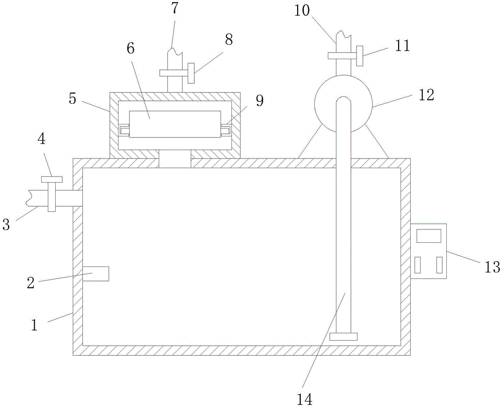
FIG. 1 is a schematic cross-sectional view of a main structure of a numerically-controlled machine tool water tank with a good filtering effect;
FIG. 2 is an enlarged schematic view of a filter box structure of a numerically-controlled machine tool water tank with a good filtering effect;
FIG. 3 is an enlarged schematic view of a three-dimensional structure of a filter frame of a numerically-controlled machine tool water tank with a good filtering effect;
FIG. 4 is a schematic structural section view of a filtering assembly of a numerically-controlled machine tool water tank with a good filtering effect.
In the figure: 1-a water tank, 2-a liquid level sensor, 3-a liquid supplementing pipe, 4-a first electromagnetic valve, 5-a filter box, 6-a filter frame, 7-a liquid return pipe, 8-a second electromagnetic valve, 9-a concave chute, 10-a liquid outlet pipe, 11-a third electromagnetic valve, 12-a liquid pump, 13-a controller, 14-a liquid inlet pipe, 15-a filter assembly, 16-a slide bar, 17-a filter screen layer, 18-an activated carbon layer and 19-a filter membrane layer.
Detailed Description
The technical solutions in the embodiments of the present invention will be described clearly and completely with reference to the accompanying drawings in the embodiments of the present invention, and it is obvious that the described embodiments are only some embodiments of the present invention, not all embodiments. Based on the embodiments in the present invention, all other embodiments obtained by a person skilled in the art without creative work belong to the protection scope of the present invention.
Referring to fig. 1 to 4, the present invention provides a technical solution: the utility model provides a digit control machine tool water tank that filter effect is good, includes water tank 1, the up end left side fixedly connected with rose box 5 of water tank 1, the up end right side fixed mounting of water tank 1 has liquid pump 12, the one end of input fixed connection feed liquor pipe 14 of liquid pump 12, the inner bottom end of water tank 1 is stretched into to the other end of feed liquor pipe 14, the output fixedly connected with drain pipe 10 of liquid pump 12, pass through the pipe connection between the bottom face of rose box 5 and the water tank 1, the up end fixedly connected with of rose box 5 returns liquid pipe 7, be provided with filter frame 6 in the rose box 5, the inside wall fixed mounting of filter frame 6 has filter assembly 15, the front side surface of rose box 5 articulates through a plurality of hinges has the filtration chamber door.
During the use, start liquid pump 12, the coolant liquid of liquid pump 12 work in with water tank 1 spouts to treating refrigerated work piece through drain pipe 10, the coolant liquid after the cooling flows into rose box 5 through returning liquid pipe 7, flow back to water tank 1 inside again on the pipeline of being connected from rose box 5 and water tank 1, realize the circulation of coolant liquid, the waste of coolant liquid has been avoided, filter assembly 15 in the rose box 5 filters the impurity in the coolant liquid, guarantee that impurity can not get into inside water tank 1 in the long-term use, do not influence the processing of cutter and other parts, whole process easy operation, high durability and convenient use, and is worth promoting.
The filtering component 15 is a filtering net layer 17, an activated carbon layer 18 and a filtering membrane layer 19 from top to bottom in sequence, the cooling liquid is filtered by the three layers, fine impurities in the cooling liquid can be fully filtered, and the filtering effect is better.
The equal fixed mounting of lateral wall has concave type spout 9 about rose box 5 is interior, the equal fixedly connected with draw runner 16 of terminal surface about filter frame 6, the draw runner 16 activity is inserted and is established in concave type spout 9, and when needs are changed filter assembly 15, operating personnel opens the filter box door, stimulates filter frame 6, makes draw runner 16 break away from concave type spout 9, and it can to get more filter assembly 15 that renews, has made things convenient for filter assembly 15's change, avoids rose box 5's jam.
Be provided with the sealing washer between rose box 5 and the filter box door, the sealing washer that sets up is used for increasing rose box 5's leakproofness, avoids the coolant liquid to spill from rose box 5.
The utility model discloses a coolant liquid supply device, including water tank 1, liquid level sensor 2, first solenoid valve 4, liquid level sensor 2, when needs fluid infusion, can open first solenoid valve 4, make the coolant liquid flow in water tank 1 through fluid infusion pipe 3 inside, convenient fluid infusion, the left end face top fixedly connected with fluid infusion pipe 3 of water tank 1, level sensor 2 is installed to the well lower part of the interior left side wall of water tank 1, install first solenoid valve 4 on the fluid infusion pipe 3, the level sensor 2 that sets up for detect the inside liquid level of water tank 1.
Install second solenoid valve 8 on the liquid return pipe 7, install third solenoid valve 11 on the drain pipe 10, controller 13 is installed to the right-hand member face of water tank 1, controller 13 is connected through the signal input part of wire and first solenoid valve 4, the signal input part of second solenoid valve 8, the signal input part of third solenoid valve 11, the signal input part of liquid pump 12, level sensor 2's signal output part electricity respectively.
Liquid level sensor 2 gives controller 13 with the data transfer of collecting, and controller 13 carries out the analysis with the data of receiving, and when the liquid level was lower, controller 13 will open first solenoid valve 2, through fluid infusion pipe 3 to the inside appropriate coolant liquid that adds of water tank 1, realizes automatic fluid infusion, and the second solenoid valve 8 of setting is used for conveniently controlling the volume of coolant liquid feed liquid according to actual need, and the third solenoid valve 11 of setting is used for conveniently controlling the volume that the coolant liquid goes out according to actual need.
It is obvious to a person skilled in the art that the invention is not restricted to details of the above-described exemplary embodiments, but that it can be implemented in other specific forms without departing from the spirit or essential characteristics of the invention. The present embodiments are therefore to be considered in all respects as illustrative and not restrictive, the scope of the invention being indicated by the appended claims rather than by the foregoing description, and all changes which come within the meaning and range of equivalency of the claims are therefore intended to be embraced therein. Any reference sign in a claim should not be construed as limiting the claim concerned.
Furthermore, it should be understood that although the present description refers to embodiments, not every embodiment may contain only a single embodiment, and such description is for clarity only, and those skilled in the art should integrate the description, and the embodiments may be combined as appropriate to form other embodiments understood by those skilled in the art.