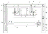
Convenient demoulding mechanism of vehicle crossbeam integrated into one piece mould
Technical Field
The utility model relates to a drawing of patterns equipment design technical field especially relates to a vehicle crossbeam integrated into one piece mould makes things convenient for demoulding mechanism.
Background
Demoulding refers to a series of operations for demoulding the steel ingot from the steel ingot mould, and the basic task of a demoulding (ingot) machine is to process the steel ingot with different shapes, sizes and single weight, complete the following process operations, freely or forcibly demoulding, demoulding of a heat preservation cap and demoulding of the ingot; the steel ingot on the bottom plate is freely or forcibly taken down, most of the existing stripper machines rely on a special clamping and ejecting tool assembled on a hoisting machine under the static force effect, various free demoulding, cap removing and ingot removing operations are completed through the opening and closing and lifting motion of a clamp and the gravity action of the steel ingot and a steel ingot mould, and forced demoulding (ingot removing) operations are performed by utilizing the ejection, blocking and relative linear motion between the ejection, blocking and the clamping and ejecting tool.
Disclosure of Invention
The utility model provides a pair of vehicle crossbeam integrated into one piece mould makes things convenient for demoulding mechanism has solved current vehicle crossbeam batch production drawing of patterns in-process and has appeared often not thoroughly with the problem that the goods is lossy.
In order to achieve the above purpose, the utility model adopts the following technical scheme:
a convenient demoulding mechanism of an integrated forming die of a vehicle beam comprises a mechanism main body, wherein a cavity is formed in the mechanism main body, a double-shaft motor is fixedly connected to the right side of the cavity, a first rotating shaft is fixedly connected to an upper output shaft of the double-shaft motor, a first screw is arranged on the lower side of the double-shaft motor, a first bevel gear is fixedly sleeved on the outer portion of the first rotating shaft, a second rotating shaft is arranged at the top of the mechanism main body, two belt pulleys are fixedly sleeved on the outer portion of the second rotating shaft, a second bevel gear is fixedly sleeved on one side, away from each other, of each belt pulley, a plurality of vertical cylinders are arranged below the second rotating shaft, third rotating shafts penetrate through the two sides of each vertical cylinder in a movable manner, belt pulleys are fixedly sleeved on the two outer sides of the third rotating shafts in a symmetrical manner, a belt is sleeved between the belt pulleys, and electric push rods are arranged on the sides, away from each other, of the belt pulleys, the mechanism comprises an electric push rod, a fine wire, a gravity block, a rotary drum, a top die, a bottom die, a rectangular buckle, a fourth rotary shaft, a sleeve, a box body, a driving motor, a second screw, a third bevel gear, a sleeve, a third bevel gear, a fourth bevel gear, a third bevel gear, a fourth shaft, a third shaft, a fourth shaft, a third shaft, telescopic one side fixedly connected with dwang, the dwang rotates with the fourth pivot to be connected.
Preferably, the inside of vertical cylinder is equipped with the diaphragm, the top fixedly connected with spring of gravity piece, one side of spring and the bottom outer wall fixed connection of diaphragm.
Preferably, the top of the vertical cylinder is fixedly connected with the outer wall of the mechanism main body, vertical plates are arranged on two sides of the rotary cylinder, and the third rotating shaft penetrates through the vertical plates in a movable mode.
Preferably, the left side of the mechanism main body is fixedly connected with a limiting rod, and the limiting rod is arranged below the bottom die.
Preferably, the first bevel gear is in meshing transmission with a second bevel gear, and the second bevel gear is in meshing transmission with a third bevel gear.
Preferably, the supporting cylinders are movably sleeved outside the two sides of the second rotating shaft, one side of each supporting cylinder is fixedly connected with a supporting block, and one side of each supporting block is fixedly connected with the inner wall of the cavity.
Compared with the prior art, the beneficial effects of the utility model are that: the utility model discloses an installation motor, the belt pulley, the gravity piece, mould isotructure, wherein drive the pivot through the biax motor and rotate, it rotates to drive a vertical section of thick bamboo through the belt pulley, mention top mould through the elastic webbing, the direction through driving motor rotation bottom mould, through making things convenient for the drawing of patterns with the gag lever post striking, the device is novel in design, and easy operation not only can prevent that goods from attaching to top mould through electric putter control gravity piece striking top mould, can also drive top mould through the elastic webbing, prevent that goods from damaging, still make things convenient for the goods drawing of patterns through the striking of driving motor control bottom mould and gag lever post simultaneously, the problem of goods drawing of patterns has effectively been solved.
Drawings
Fig. 1 is a schematic view of a three-dimensional structure of a convenient demoulding mechanism of an integrated forming mould for a vehicle crossbeam provided by the utility model;
FIG. 2 is a schematic view of a front sectional view of a convenient demolding mechanism of the vehicle beam integral forming mold according to the present invention in a non-working state;
FIG. 3 is a schematic view of a front sectional view of a convenient demolding mechanism of the vehicle beam integral molding mold according to the present invention;
fig. 4 is the utility model provides a vehicle crossbeam integrated into one piece mould makes things convenient for demoulding mechanism gravity piece part enlarged state front view sectional structure sketch map.
In the figure: the mechanism comprises a mechanism body 1, a double-shaft motor 2, a first screw rod 3, a first rotating shaft 4, a first bevel gear 5, a second rotating shaft 6, a second bevel gear 7, a belt pulley 8, a third rotating shaft 9, a rotating drum 10, an electric push rod 11, a fine wire 12, a spring 13, a gravity block 14, an elastic belt 15, a top mold 16, a rectangular buckle 17, a bottom mold 18, a fourth rotating shaft 19, a sleeve 20, a box 21, a driving motor 22, a belt 23, a vertical cylinder 24, a second screw rod 25, a third bevel gear 26, a limiting rod 27, a cavity 28 and a rotating rod 29.
Detailed Description
The technical solutions in the embodiments of the present invention will be described clearly and completely with reference to the accompanying drawings in the embodiments of the present invention, and it is obvious that the described embodiments are only some embodiments of the present invention, not all embodiments.
Referring to fig. 1-4, an example provided by the present solution: a convenient demoulding mechanism of a vehicle crossbeam integrated forming mould comprises a mechanism main body 1, a cavity 28 is arranged in the mechanism main body 1, a double-shaft motor 2 is fixedly connected to the right side of the cavity 28, a first rotating shaft 4 is fixedly connected to an upper output shaft of the double-shaft motor 2, a first screw 3 is arranged on the lower side of the double-shaft motor 2, a first bevel gear 5 is fixedly sleeved on the outer portion of the first rotating shaft 4, a second rotating shaft 6 is arranged on the top of the mechanism main body 1, two belt pulleys 8 are fixedly sleeved on the outer portion of the second rotating shaft 6, a second bevel gear 7 is fixedly sleeved on one side, away from each other, of each belt pulley 8, a plurality of vertical cylinders 24 are arranged below the second rotating shaft 6, third rotating shafts 9 movably penetrate through the two sides of each vertical cylinder 24, belt pulleys 8 are symmetrically and fixedly sleeved on the outer portions of the third rotating shafts 9, a belt 23 is sleeved between the belt pulleys 8, and an electric push rod 11 is arranged on one side, away from each belt pulley 8, a fine wire 12 is fixedly connected to an output shaft of the electric push rod 11, a gravity block 14 is fixedly connected to one side of the fine wire 12, a rotary drum 10 is fixedly sleeved outside a third rotary shaft 9, an elastic belt 15 is wound outside the rotary drum 10, a top mold 16 is arranged below the third rotary shaft 9, a bottom mold 18 is arranged at the bottom of the top mold 16, a rectangular buckle 17 is fixedly connected to the outer wall of the top mold 16, fourth rotary shafts 19 are fixedly connected to two sides of the bottom mold 18, a sleeve 20 is sleeved on an external thread of the first screw 3, a box 21 is fixedly connected to one side of the sleeve 20, a driving motor 22 is fixedly connected to the inner wall of the bottom of the box 21, an output shaft of the driving motor 22 is fixedly connected to the right side of the fourth rotary shaft 19, a second screw 25 is rotatably connected to the left side of the mechanism body 1, a third bevel gear 26 is fixedly sleeved on the outer wall of the top of the second screw 25, and a sleeve 20 is sleeved on an external thread of the second screw 25, a rotating rod 29 is fixedly connected to one side of the sleeve 20, and the rotating rod 29 is rotatably connected to the fourth rotating shaft 19.
In this embodiment, a transverse plate is arranged inside the vertical tube 24, the top of the gravity block 14 is fixedly connected with the spring 13, and one side of the spring 13 is fixedly connected with the outer wall of the bottom of the transverse plate.
In this embodiment, the top of the vertical tube 24 is fixedly connected to the outer wall of the mechanism body 1, the vertical plates are disposed on two sides of the rotating tube 10, and the third rotating shaft 9 movably penetrates through the vertical plates.
In this embodiment, a limiting rod 27 is fixedly connected to the left side of the mechanism body 1, and the limiting rod 27 is disposed below the bottom mold 18.
In the embodiment, the first bevel gear 5 is in meshing transmission with the second bevel gear 7, and the second bevel gear 7 is in meshing transmission with the third bevel gear 26.
In this embodiment, the supporting cylinders are movably sleeved outside the two sides of the second rotating shaft 6, one side of each supporting cylinder is fixedly connected with a supporting block, and one side of each supporting block is fixedly connected with the inner wall of the cavity 28.
The working principle is that firstly, the double-shaft motor 2 is started, the rotation of the output shaft of the double-shaft motor 2 can drive the first rotating shaft 4 to rotate, the rotation of the first rotating shaft 4 can drive the first bevel gear 5 to rotate, the rotation of the first bevel gear 5 can drive the second bevel gear 7 to rotate, the rotation of the second bevel gear 7 can drive the second rotating shaft 6 to rotate, the rotation of the second rotating shaft 6 can drive the belt pulley 8 to rotate, the rotation of the belt pulley 8 can drive the belt 23 to rotate, the rotation of the belt 23 can drive the third rotating shaft 9 to rotate, the rotation of the third rotating shaft 9 can drive the rotating drum 10 to rotate, the rotation of the rotating drum 10 can drive the furling of the elastic belt 15, the furling of the elastic belt 15 can drive the top die 16 to move, at the moment, the electric push rod 11 is started, the movement of the output shaft of the electric push rod 11 can enable the fine wire 12 wound on the outer wall to move downwards under the action of the gravity block 14, the gravity block 14 impacts the outside of the top mold 16 to perform a demolding function, so as to prevent a product from being attached to the top mold 16, the rotation of the output shaft of the dual-shaft motor 2 can drive the first screw rod 3 and the second screw rod 25 to rotate, the rotation of the first screw rod 3 can drive the sleeve 20 to move, the rotation of the second screw rod 25 can drive the sleeve 20 to move, so that the bottom mold 18 can be moved downwards, the driving motor 22 is started, the rotation of the output shaft of the driving motor 22 can drive the bottom mold 18 to rotate, when the bottom mold 18 is impacted by the limiting rod 27 in the rotation process, the product demolding can be facilitated, after the demolding operation is finished, the electric push rod 11 is started, the output shaft of the electric push rod 11 extends out to be connected with the third rotating shaft 9, the dual-shaft motor 2 rotates in the opposite direction to drive the electric push rod 11 to rotate, and meanwhile, the fine wire 12 can be wound on the electric push rod 11 under the rotation of the output shaft, at the same time, the spring 13 exerts an opposing force on the weight block 14, so that the entire stripping mechanism is finished.
The above, only be the concrete implementation of the preferred embodiment of the present invention, but the protection scope of the present invention is not limited thereto, and any person skilled in the art is in the technical scope of the present invention, according to the technical solution of the present invention and the utility model, the concept of which is equivalent to replace or change, should be covered within the protection scope of the present invention.