Disclosure of Invention
The utility model aims to solve the technical problem that realize a portable gas detection system, can inspect in the normal formation process, guarantee reliability, the promptness that detects.
In order to realize the purpose, the utility model discloses a technical scheme be: the utility model provides a gas detection system, the input of extraction pump connects sampling probe through the sampling tube, the output of extraction pump is through pipe connection analysis appearance, data output device is connected to the analysis appearance, extraction pump and analysis appearance are connected with the PLC controller.
The analyzer is an infrared analyzer for analyzing the content of the hydrogen chloride, the sampling tube is a tetrafluoroethylene fluoroplastic tube, and a heat tracing band for heating and heat preservation is covered outside the sampling tube.
And the air inlet and the air outlet of the sampling probe are both provided with filters.
And the air outlet of the analyzer is connected with a compressed air pipe.
The sampling tube is connected to compressed air pipe bypass shunt tubes all the way, all be equipped with the valve on shunt tubes and the sampling probe, two valves are connected to the PLC controller and control signal to valve is exported.
The extraction pump, the analyzer, the data output device and the power supply are fixed in the control box, the bottom of the control box is provided with a travelling wheel, the sampling tube is a hose, the data output device is a paperless recorder, and the pipe joint of the compressed air pipe extends out of the control box.
The power supply end of the PLC is connected with power supply equipment through a power line, and the power supply equipment is a power supply outside the control box or a battery in the control box.
A sampling port is formed in the side face of the chimney to be detected, a detachable sealing cover plate is arranged on the sampling port, and after the cover plate is taken down, the sampling probe extends into the chimney through the sampling port.
The sampling tube is characterized in that a flange is arranged outside the sampling port, a mounting hole matched with the flange is formed in the cover plate, the cover plate is fixed on the flange through a screw penetrating through the mounting hole, a fixing plate is fixed on the sampling tube, a mounting hole is formed in the fixing plate, and the fixing plate is fixed on the flange through a screw penetrating through the mounting hole.
The utility model discloses detecting system can be under the normal production state of pickling process, realize the hydrogen chloride content that the on-line measuring chimney discharged, adopt simple and easy sampling connected mode, convenient to detach to realize removing the hydrogen chloride gas content that discharges a plurality of chimneys and detect, guide production in real time, sampling process is whole heats to 180 ℃, acidic corrosion and component loss that the flue gas condensation caused have been avoided, reduce because of the moisture of the gas of being surveyed to the influence of measuring, the original flue gas of direct measurement has been realized, the testing result is true and reliable, reduce the detection cost.
Detailed Description
The following description of the embodiments with reference to the drawings is intended to illustrate the present invention in further detail, such as the shapes and structures of the components, the mutual positions and connections between the components, the functions and working principles of the components, the manufacturing process, and the operation and use methods, etc., so as to help those skilled in the art understand the present invention more completely, accurately and deeply.
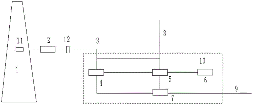
The detection system shown in fig. 1 is composed of a sampling probe 2, a sampling tube 3, an extraction pump 4, an analyzer 5, a PLC controller 7 and a data output device. At 1 installation standard flange sample connection of chimney under test, sampling probe 2 and sample connection flange joint because need stretch into in the chimney 1 of high temperature, sampling probe 2, sampling tube 3, the equal sampling high temperature resistance equipment of aspiration pump 4. Through set up the sample connection that has the flange on chimney 1, can conveniently open at any time or seal chimney 1, take a sample to test as required, the sample connection is equipped with the sealed apron of detachable, take off the apron after sample probe 2 stretches into in chimney 1 by the sample connection, cover the apron and then can shutoff sample connection, be equipped with on the apron with flange complex mounting hole, the apron is fixed the apron on the flange through the screw that passes the mounting hole, conveniently carry out the dismouting to the apron, be fixed with the fixed plate on the sampling tube 3, sample tube 3 passes the fixed plate promptly, can be with fixed plate and 3 rigid couplings of sampling tube, also can be with fixed plate and 2 rigid couplings of sample probe, be equipped with the mounting hole on the fixed plate, the fixed plate is fixed the fixed plate on the flange through the screw that passes the mounting hole, then can fix sample probe 2 in chimney 1.
Sampling probe 2 connects extraction pump 4 through sampling tube 3, in order to avoid the pipeline inside to receive the dust influence, and lead to the fact the damage to analysis appearance 5, sampling probe 2's air inlet is equipped with one-level filter 11, and the gas outlet is equipped with secondary filter 12, stretches into the smoke and dust that exist in the flue in one-level filter 11 can filter the flue gas promptly, and the probe has secondary filter 12 to carry out the meticulous filtration of high temperature before being connected with sampling tube 3 line outside the flue.
The sampling tube 3 and the sampling probe 2 contain electric heaters, namely, the sampling tube is coated with a heating heat-preserving heat tracing band, so that the sampling probe 2 is inserted into a sampling port, filtered by the sampling tube 3 and a filter and heated to 180 ℃ by the heater, the sampling tube 3 is preferably a high-temperature-resistant and corrosion-resistant polytetrafluoroethylene fluorine plastic tube, can continuously work at the temperature below 220 ℃, the pipeline can be bent and is convenient to collect, and the movable installation is realized. The condensation of moisture and acidic components in the flue gas is avoided by keeping the temperature in the range of 180 ℃.
The analyzer 5 adopts an infrared analyzer 5 capable of analyzing the content of hydrochloric acid, the analyzer 5 measures the concentration of the components by the beer-Lambert principle, in order to measure the concentration of the components to be measured, the emitted light can be measured at the characteristic absorption wavelength of the components, and according to the original light intensity and the light intensity after the absorption of the gas to be measured, the concentration and the measuring range of the components to be measured are calculated by a formula: hydrogen chloride 0-100mg/m3. The analyzer 5 employs a single beam dual wavelength and gas filtration related technique. The analyzer 5 measures the high temperature and constant temperature control of the air chamber, a protective filter is arranged at the inlet of the measuring air chamber, and the built-in flowmeter gives an alarm when the flow is lower than a set value. The hydrogen chloride data detected by the infrared analyzer 5 are output to the paperless recorder 6, and the paperless recorder 6 records the detected hydrogen chloride data and stores and files the data.
The analyzer 5 measures the component concentration by the beer-Lambert principle, the specific working principle is as follows:
A=logI 0/I=e×c×d (1)
in formula (1):
a- - - -absorbance (attenuation of light intensity after absorption of measured gas)
I0-original light intensity of emitted light
I-light intensity after absorption of measured gas
e-absorption coefficient
c-concentration of gas to be measured
d-optical path length
It can be deduced from formula (1) that, in order to measure the concentration of a component to be measured, the intensity of the emitted light, the original intensity (I0) and the intensity (I) of the light absorbed by the gas to be measured, are measured at the characteristic absorption wavelength of the component, and the concentration (C) of the component to be measured is calculated from formula (1): hydrogen chloride 0-100mg/m3Zero drift: less than 1%, drift of measuring range: ± 2%, sensitivity drift: less than or equal to +/-2%, and temperature influence: < + -. 2%/10K.
The system is provided with a PLC (programmable logic controller) 7 for overall control, and the PLC 7 controls the temperature of the sampling probe 2 and the work of the extraction pump 4 in a centralized manner and monitors and protects the relevant states. The PLC controller 7, the air suction pump, the analyzer 5 and the paperless recorder 6 are integrated into a control box 10, and the control box 10 is provided with a traveling wheel which is convenient to move. The power supply point of the PLC controller 7 is connected to a 220VAC power supply of the control box 10 through a power line 9, and is supplied with power by the heater and the system.
The external standard instrument air supply of control box 10 is used for blowing high temperature probe and 5 measurement air chambers of analysis appearance after filtration treatment, can constitute the blowback system, and the gas outlet of extraction pump 4 is equipped with a compressed air pipe 8 promptly, can be through the external standard instrument air supply of compressed air pipe 8 connection control box 10, can regard compressed air pipe 8 as the blast pipe under the non-blowback condition. The air blown into the compressed air pipe 8 sweeps the probe, so that the blockage of the probe is prevented, and the long-term durability of the probe is ensured; the sampling tube 3 is connected by a bypass pipeline with a valve, and the back flushing operation is carried out at the same time.
In addition, a pneumatic stop valve is arranged in the sampling probe 2, and the gas circuit can be closed when the system is suddenly powered off, so that the sample gas is prevented from being conveyed. The sampling probe 2 works at a high temperature of more than 180 ℃ and is far higher than the acid dew point of the gas of the hydrogen chloride, so that the high-temperature sampling technology can completely avoid the corrosion of equipment caused by condensation and dewing of the acid gas and reduce the loss of the measured components. Because the measurement process is carried out at a high temperature of 180 ℃, the smoke is in a gaseous state, the corrosivity is very low, dust is easy to remove by back flushing, and the use reliability is improved. The amount of maintenance is also reduced. The standard flange connection is convenient to disassemble, and mobile measurement can be realized.
The system is connected with a power supply and an air source of a control box 10 before use, a sampling probe 2 and a connecting sampling tube 3 line are installed, the system starts to measure when the system is heated to the working temperature of 180 degrees, and data are measured by an analyzer 5 and recorded and filed by a paperless recorder 6. The shutdown system is cooled to normal room temperature, and power and air supply can be dismantled after the outage, sampling probe 2 is dismantled, sampling tube 3 is dismantled, and after the collection and arrangement, the next measuring point is moved.
The system realizes online detection of the hydrogen chloride content discharged by the chimneys 1 by adopting a simple sampling connection mode, is convenient to disassemble, and realizes mobile detection of the hydrogen chloride gas content discharged by the chimneys 1; the whole course of the sampling process is heated to 180 degrees, so that the acidic corrosion and component loss caused by flue gas condensation are avoided, the influence of the moisture of the gas to be detected on the measurement is reduced, the direct measurement of the original flue gas is realized, the detection result is real and reliable, and the detection cost is reduced.
The present invention has been described above with reference to the accompanying drawings, and it is to be understood that the invention is not limited to the specific embodiments described above, and that the invention is not limited to the specific embodiments described above, but rather is intended to cover various insubstantial modifications of the inventive method and solution, or its application to other applications without modification.