SUMMERY OF THE UTILITY MODEL
The utility model aims to overcome current electric kettle owing to be equipped with the switch button on the kettle body, consequently not only influence its outward appearance, increase the not enough of the product packaging design degree of difficulty moreover, provide one kind and integrate electric kettle on the handle with control switch, start through handle control heating element.
In order to solve the technical problem, the utility model discloses a following technical scheme:
an electric kettle comprises a kettle body with a water boiling cavity, a heating element, a temperature controller, a micro switch and a U-shaped handle, wherein the heating element, the temperature controller and the micro switch are positioned on the lower side of the water boiling cavity, the U-shaped handle is positioned on the upper side of the kettle body and comprises a supporting section, a movable section and a holding section, the holding section is fixedly connected with the supporting section and the movable section, the supporting section is fixedly connected to one side of the kettle body, the other side of the kettle body is provided with a sliding groove corresponding to the micro switch, and the movable section is provided with a trigger assembly which penetrates through the sliding groove and extends to the upper side of the micro switch; the trigger assembly is operable to move downwardly along the chute to trigger the microswitch when the active segment is applied with a downward force and to move upwardly to reset with the active segment when the active segment is not applied with the force.
Compared with the prior art, the utility model provides an electric kettle has cancelled current switch button that sets up alone in the kettle body outside, the replacement is through setting up U type handle, and fix the support section of U type handle on the kettle body, set up the section of will moving into the form that can move about from top to bottom, when receiving decurrent effort, elastic deformation takes place for U type handle, make the section of moving about drive trigger the subassembly and move down and trigger micro-gap switch, thereby start heating element, after loosening U type handle, the handle recovers to drive trigger the subassembly with the section of moving about and upwards to reset and break away from micro-gap switch, this kind not only can make the product more pleasing to the eye succinct with the setting mode of control switch integration at the handle, the packing of product has been simplified, and its operating mode convenient and fast, the operator only need press down the handle alright trigger micro-gap switch of handle and start heating element.
Further, the triggering assembly comprises a first limiting part connected with the movable section and a second limiting part movably abutted to the inner wall of the kettle body from top to bottom in a controlled mode, the first limiting part is provided with a guide part inserted into the sliding groove, the guide part is matched with the sliding groove in an upward size perpendicular to the activity direction of the triggering assembly, the first limiting part is detachably connected with the second limiting part, the first limiting part and the second limiting part are movably clamped on two sides of the sliding groove, so that the kettle body is connected with the U-shaped handle, the U-shaped handle can be prevented from swinging left and right in the moving mode of the guide part, and the U-shaped handle is ensured to be tightly matched with the kettle body.
Further, the mounting hole is seted up to the corresponding spout of activity section, and first locating part includes outer loop, fastener and joint spare, and the outer loop butt is in the outside of mounting hole, and the joint spare includes spacing portion and locates the fixture block that spacing position is close to the relative both sides of second locating part one end, and spacing portion butt is between activity section and kettle body, and the fixture block extends to the inboard and stretches into the spout and form the guide part, and the fixture block joint has seted up the via hole in the relative both sides of second locating part in spacing portion, and the fastener passes outer loop and via hole to be connected with the second locating part, the outer loop is equipped with the spacing step that extends to the inboard, the fastener is equipped with the butt and is in protruding edge on the spacing step. The first limiting part is arranged in a mode convenient to install and detach, and the first limiting part and the second limiting part are firmly connected.
Furthermore, the second locating part is provided with a clamping groove matched with the clamping block, two opposite sides of the second locating part, which are positioned in the clamping groove, are respectively provided with a top block which is abutted against the inner wall of the kettle body, the second locating part is provided with a triggering part which extends to one side far away from the first locating part, the triggering part is in movable contact with the micro switch, and the top block is arranged to enable the U-shaped handle to be in close fit with the kettle body when the U-shaped handle moves.
Further, it is equipped with the lamp body to correspond the subassembly that triggers in the kettle body, and the outer end of fastener is equipped with the lid, and lid, fastener and second locating part set up to leaded light material, and the lamp body makes the lid show luminous effect, and above-mentioned luminous mode can supply the operator to learn electric kettle's operating condition through luminous effect, sends the green glow when for example stopping heating, sends the green glow when heating, and science and technology sense is stronger.
Furthermore, the holding section is arranged to be in smooth transition connection with the supporting section and the moving section, and the arrangement mode of the arc structure accords with human mechanics, so that the holding section is more suitable for being held by an operator.
Furthermore, the thickness that the section of gripping is close to one side of the movable section is greater than the thickness that it is close to one side of the support section, and this kind of setting mode not only more can be fit for the operator to grab and take, and when pressing the section of gripping moreover, because the thickness that the section of gripping is close to one side of the support section is thinner, consequently the section of gripping takes place the deformation easily with the movable section and moves down and trigger micro-gap switch to it is more laborsaving.
Furthermore, the distance between the support section and the central line of the kettle body is greater than the distance between the movable section and the central line of the kettle body, and the arrangement mode provides certain tension force to enable the movable section to be more tightly attached to the sliding groove, so that the U-shaped lifting handle is prevented from shaking left and right during movement.
Further, the temperature controller is including the NTC temperature sensor that is used for the monitoring to boil the chamber temperature, and when the NTC temperature sensor sensed the chamber temperature of boiling and reached the threshold value, control heating element stop heating, this kind of control by temperature change mode and current adoption steam make the control by temperature change mode that the sheetmetal warp compare, and the temperature control effect is more accurate to can not lead to the fact the damage to the inside electric elements of kettle body.
Detailed Description
The following describes embodiments of the present invention with reference to the drawings. In the description of the present invention, it should be noted that the terms "upper", "lower", "inner", "outer", and the like indicate orientations or positional relationships based on the orientations or positional relationships shown in the drawings, and are only for convenience of description and simplification of description, but do not indicate or imply that the device or element referred to must have a specific orientation, be constructed in a specific orientation, and be operated, and thus should not be construed as limiting the present invention.
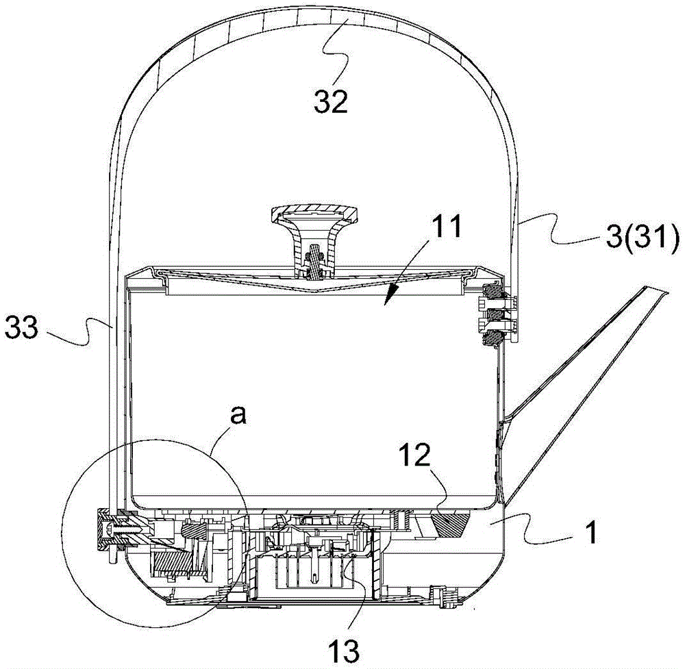
Referring to fig. 1 to 3 and 5, the present embodiment provides an electric kettle, which includes a kettle body 1 and a base 2, wherein the kettle body 1 and the base 2 are detachably and electrically connected through a coupler, a water boiling cavity 11 with an open upper side, a heating element 12 located at the lower side of the water boiling cavity 11, a temperature controller 13 and a micro switch 14, and a U-shaped handle 3 located at the upper side of the kettle body 1 are provided in the kettle body 1.
Referring to fig. 1 to 5, the U-shaped handle 3 includes a supporting section 31, a movable section 33, and a holding section 32 fixedly connecting the supporting section 31 and the movable section 33, an end of the supporting section 31 is fixed to one side of the kettle body 1 by a screw, the other side of the kettle body 1 is provided with a sliding slot 15 corresponding to the micro switch 14, the movable section 33 is provided with a triggering component (401,402) penetrating the sliding slot 15 and extending to an upper side of the micro switch 14, the triggering component (401,402) can be controlled to move downwards along the sliding slot 15 to trigger the micro switch 14 when the movable section 33 is applied with a downward acting force, and can move upwards along the movable section 33 to reset when the movable section 33 is not applied with the acting force.
The utility model discloses a theory of operation does: because one end of the U-shaped handle 3 is fixed on the kettle body 1, the other end can move up and down, when an operator presses the handle 3 downwards or directly holds the movable section 33 to pull downwards, a downward acting force is applied to the movable section 33, at the moment, the U-shaped handle 3 elastically deforms, concretely, the holding section 32 and the movable section 33 deform downwards by taking the upper end part of the supporting section 31 as a fulcrum, so that the triggering components (401 and 402) move downwards along with the movable section 33, and the micro switch 14 is triggered to send a starting signal to the control circuit to control the heating element 12 to start to boil water, when water boiling starts, the operator can release the hand, the movable section 33 resets upwards, so that the triggering components (401 and 402) are separated from the micro switch 14, when water boiling reaches a preset time, the temperature controller 13 senses the temperature of the water boiling cavity 11, when a threshold value is reached, a stopping signal is sent to the control circuit to close the heating element 12, and finishing water boiling.
Referring to fig. 1 to 5, in a specific embodiment, the triggering assembly (401,402) includes a first limiting member 401 and a second limiting member 402, the first limiting member 401 is connected to the movable section 33, the second limiting member 402 can be controlled to abut against the inner wall of the kettle body 1 in a vertically movable manner, the first limiting member 401 is provided with a guiding portion 41 inserted into the sliding slot 15, the guiding portion 41 is adapted to the size of the sliding slot 15 in the direction perpendicular to the movement direction of the triggering assembly (401,402), the first limiting member 401 is detachably connected to the second limiting member 402, the first limiting member 401 and the second limiting member 402 are movably clamped at two sides of the sliding slot 15, so as to achieve connection between the kettle body 1 and the U-shaped handle 3, the guiding portion 41 is arranged in a manner that the U-shaped handle 3 is prevented from swinging left and right when moving, and close fit between the U-shaped handle 3 and the kettle body 1 is ensured.
Further, the distance between the supporting section 31 and the central line of the kettle body 1 is greater than the distance between the movable section 33 and the central line of the kettle body 1, and the arrangement mode provides a certain tension force to enable the movable section 33 to be more tightly attached to the sliding groove 15, so that the U-shaped lifting handle 3 is prevented from shaking left and right during movement.
Referring to fig. 2 to 5, in a specific embodiment, the first limiting member 401 includes an outer ring 42, a fastening member 43, a clamping member 44 and a cover 45, the movable section 33 has a mounting hole 331 corresponding to the sliding slot 15, the outer ring 42 abuts against the outer side of the mounting hole 331, the clamping member 44 includes a limiting portion 441 and a clamping block 442 disposed at the limiting portion 441 and located at two opposite sides of one end close to the second limiting member 402, the limiting portion 441 abuts against between the movable section 33 and the kettle body 1, the clamping block 442 extends inward and extends into the sliding slot 15 to form the above-mentioned guiding portion 41, the second limiting member 402 has a clamping slot 403 adapted to the clamping block 442, the clamping block 442 is clamped into the clamping slot 403, the limiting portion 441 has a through hole 46, the fastening member 43 sequentially passes through the outer ring 42 and the through hole 46 to be connected to the second limiting member 402, preferably, the fastening member 43 is connected to the second limiting member 402 by a screw, the outer ring 42 has a limiting step 421 extending inward, the fastening member 43 is provided with a convex edge 432 abutting against the limiting step 421, the outer end of the fastening member 43 is provided with a lamp cover installation groove 431, the cover body 45 is installed in the lamp cover installation groove 431, the installed cover body 45 is flat with the outer end surface of the outer ring 42, the installation mode of the first limiting member 401 is convenient for installation and disassembly, and the first limiting member 401 and the second limiting member 402 are firmly connected.
Referring to fig. 4 and 5, the two opposite sides of the second limiting member 402 located on the slot 403 are respectively provided with a top block 47 abutting against the inner wall of the kettle body 1, the second limiting member 402 is provided with a triggering portion 48 extending to a side away from the first limiting member 401, the triggering portion 48 is in movable contact with the micro switch 14, and is used for triggering the micro switch 14 when the movable section 33 moves downward, and the top block 47 is arranged to enable the U-shaped handle 3 to be tightly matched with the kettle body 1 when the U-shaped handle 3 moves.
Referring to fig. 3 to 5, a lamp body 16 is disposed in the kettle body 1 corresponding to the trigger assemblies (401,402), the trigger assemblies (401,402) at least include the cover 45, the fastening member 43 and the second limiting member 402, and the lamp body 16 enables the cover 45 to exhibit a light emitting effect; certainly, in order to improve the light guide efficiency, the trigger assemblies (401 and 402) are made of light guide materials so as to enhance the light conduction, the light emitting mode can be used for an operator to know the working state of the electric kettle through the light emitting effect, for example, green light is emitted when the electric kettle stops heating, green light is emitted when the electric kettle is heating, and the scientific sense is stronger.
Referring to fig. 2, in a specific arrangement, the holding section 32 is configured to be an arc structure in smooth transition connection with the supporting section 31 and the moving section 33, in order to facilitate grasping by an operator, the thickness of the holding section 32 near the moving section 33 is greater than the thickness of the holding section 32 near the supporting section 31, specifically, the thickness of the holding section 32 gradually increases from one end near the supporting section 31 to one end near the moving section 33, the above arrangement not only conforms to human mechanics, but also when the holding section 32 is pressed, because the thickness of the holding section 32 near the supporting section 31 is thinner, the holding section 32 and the moving section 33 are easily deformed and move down to trigger the microswitch 14, thereby saving more labor.
Referring to fig. 2, in a specific arrangement, the U-shaped handle 3 is made of an integrally formed plastic material, which has a light weight and a good elastic deformation and recovery effect.
Referring to fig. 2 and 5, in a specific setting mode, the temperature controller 13 includes an NTC temperature sensor for monitoring the temperature of the water boiling chamber 11, the conventional electric kettle generally employs a steam temperature sensing element, when water boils, steam generated by the steam temperature sensing element deforms a bimetal of the steam temperature sensing element, and a lever principle is used to push the power switch to power off, the temperature control mode needs to make steam flow into the kettle body 1, even if a sealing structure is specially arranged, it is difficult to avoid the problems of rusting of parts, even short circuit, water accumulation and the like due to internal moisture after long-term use, therefore, the electric kettle of the embodiment monitors the temperature of the water boiling chamber 11 by using the NTC temperature sensor, once the temperature reaches a threshold value, the power supply can be immediately switched off by a corresponding program, the conventional temperature control mode is changed, the service life of the electric element is longer, and the program employs a circuit control means in the prior art, is not the innovation point of the utility model.
Compared with the prior art, the electric kettle provided by the utility model cancels the existing switch button which is arranged on the outer side of the kettle body 1 independently, and is replaced by arranging the U-shaped handle 3, the supporting section 31 of the U-shaped handle 3 is fixed on the kettle body 1, the movable section 33 is set to be movable up and down, when the U-shaped handle 3 is acted by a downward acting force, the U-shaped handle 3 is elastically deformed, so that the movable section 33 drives the trigger assemblies (401,402) to move downwards to trigger the microswitch 14, thereby starting the heating element 12, when the U-shaped handle 3 is released, the handle 3 is restored so that the movable section 33 drives the trigger assemblies (401,402) to reset upwards to be separated from the microswitch 14, the arrangement mode of integrating the control switch on the handle 3 not only can lead the product to be more beautiful and concise, simplifies the packaging of the product, and the operation mode is convenient and quick, and an operator can trigger the micro switch 14 to start the heating element 12 only by pressing the handle 3 downwards.
Variations and modifications to the above-described embodiments may occur to those skilled in the art, in light of the above teachings and teachings. Therefore, the present invention is not limited to the specific embodiments disclosed and described above, and some modifications and changes to the present invention should fall within the protection scope of the claims of the present invention. Furthermore, although specific terms are employed herein, they are used in a generic and descriptive sense only and not for purposes of limitation.