Anti-silting lifting device for inverted siphon
Technical Field
The utility model relates to a sewage treatment device technical field, more specifically relates to a heavy and long-pending lifting means of preventing silting up of siphon falls.
Background
With the continuous expansion of urban construction scale, the management, maintenance, repair and dredging of sewage pipelines are also increased. The current inverted siphon pipe is because inside sewage flow is big, appears the situation of inverted siphon siltation easily, blocks up, seriously influences the sewage overflow capacity of inverted siphon pipe, leads to sewage to overflow even, causes environmental pollution, and then influences the traffic in city.
SUMMERY OF THE UTILITY MODEL
In order to overcome the defects of the prior art, the utility model aims to solve the technical problem that a falling siphon prevents siltation and promotes equipment is proposed, utilizes filter equipment to filter the impurity in the sewage, prevents that impurity from silting up in falling siphon, utilizes the bold impurity of reducing mechanism in with the sewage to smash simultaneously, prevents that impurity from blockking up the filter screen, has improved the filter effect.
To achieve the purpose, the utility model adopts the following technical proposal: the utility model provides a falling siphon prevents siltation and promotes equipment, including the intake shaft, filter equipment, the elevator pump, reducing mechanism, filter residue collection device and level sensor, filter equipment and elevator pump all set firmly in the bottom of intake shaft, filter equipment includes rose box and filter screen, first filter chamber has been seted up in the rose box, reducing mechanism sets firmly in the top of first filter chamber, the spout has been seted up to the lateral wall of first filter chamber, the gliding setting of filter screen is in the spout, and the butt has first compression spring between filter screen and the spout, the top of rose box is provided with the inlet tube, the rose box is connected with the elevator pump through first pipeline, filter residue collection device sets up in one side of rose box, the fixed drainage well inner wall of level sensor, level sensor and elevator pump electric connection.
The utility model discloses among the technical scheme of preferred, reducing mechanism includes first motor, bull stick and blade, first motor set firmly in the filter box top, and first motor output shaft runs through the filter box and extends to in the first filter chamber, set firmly more than two bull sticks on the first motor output shaft, the even rigid coupling in periphery of bull stick has more than two blades.
In the preferred technical scheme of the utility model, the filter residue collecting device comprises a shell, a control box, a conveyor belt, filter plates, a second motor, a sector gear, a first rotating shaft, a second rotating shaft, a connecting rod, a push plate, a second compression spring and a cam, wherein the control box is arranged at one side of the shell, a second filter cavity is arranged in the shell and is communicated with the first filter cavity through a first through hole and a second through hole, the first rotating gear, the second rotating gear and the third rotating gear are all rotationally arranged in the second filter cavity, the conveyor belt is connected among the first rotating gear, the second rotating gear and the third rotating gear in a transmission fit manner, more than two filter plates are fixedly arranged on the conveyor belt, a driving cavity is arranged in the control box and is communicated with the second filter cavity through a third through hole, and a first rotating shaft is rotationally arranged between the second filter cavity and the driving cavity, one end of a first rotating shaft is fixedly connected with a first rotating gear, the other end of the first rotating shaft extends into a driving cavity and is fixedly connected with a first bevel gear, a driving cavity is formed in a control box and is positioned above the driving cavity, a second rotating shaft is rotatably arranged between the driving cavity and the driving cavity, one end of a second rotating shaft extends into the driving cavity and is fixedly connected with a second bevel gear, the first bevel gear is meshed with the second bevel gear, the other end of the second rotating shaft extends into the driving cavity and is fixedly connected with a fourth rotating gear, a second motor is embedded in the top wall of the driving cavity, an output shaft of the second motor penetrates through the driving cavity and extends into the driving cavity, a sector gear is fixedly arranged on an output shaft of the second motor and is meshed with a fourth rotating gear, a third bevel gear is fixedly connected with the free end of the output shaft of the second motor, a third rotating shaft is rotatably arranged at the bottom of the driving cavity, and a fourth bevel gear meshed with the third bevel gear is arranged on the third rotating shaft, a cam is arranged at the position of the third rotating shaft, which is far away from the fourth bevel gear, a supporting plate is fixedly arranged at the bottom of the driving cavity, one end of a connecting rod is fixedly connected with the rubber block, the other end of the connecting rod penetrates through the supporting plate and extends into the driving cavity to be fixedly connected with the push plate, a second compression spring is connected between the push plate and the supporting plate in a butting mode, the second compression spring is sleeved on the connecting rod, the cam is abutted to the push plate, and a scum outlet is formed in the other side of the shell.
In the technical scheme of the utility model, the scum pipe one end with scum export fixed connection, the scum pipe the other end and store up the sediment jar can dismantle and be connected.
In the preferred technical scheme of the utility model, the filter plate is in evenly set up on the conveyer belt.
The utility model has the advantages that:
the utility model provides a pair of fall siphon and prevent siltation lifting means utilizes filter equipment to filter the impurity in the sewage, prevents that impurity from silting up in falling the siphon, utilizes the bold impurity of reducing mechanism in with the sewage to smash simultaneously, prevents that impurity from blockking up the filter screen, has improved the filter effect.
Drawings
Fig. 1 is a schematic structural diagram of an inverted siphon siltation prevention lifting device according to an embodiment of the present invention;
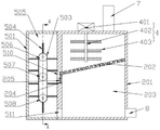
FIG. 2 is a schematic view of the structure of the filter device;
FIG. 3 is a cross-sectional view taken along line A-A of FIG. 2;
fig. 4 is a sectional view taken in the direction B-B in fig. 3.
In the figure:
1-water inlet well, 2-filtering device, 201-filtering box, 202-filtering screen, 203-first filtering cavity, 204-chute, 205-first compression spring, 3-lift pump, 4-crushing device, 401-first motor, 402-rotating rod, 403-blade, 5-filter residue collecting device, 501-shell, 502-control box, 503-conveying belt, 504-filter plate, 505-second filtering cavity, 506-first rotating gear, 507-second rotating gear, 508-third rotating gear, 509-driving cavity, 510-first through hole, 511-second through hole, 512-first rotating shaft, 513-second rotating shaft, 514-first bevel gear, 515-second bevel gear, 516-driving cavity, 517-fourth rotating gear, 518-a second motor, 519-a sector gear, 520-a third rotating shaft, 521-a third bevel gear, 522-a fourth bevel gear, 523-a supporting plate, 524-a rubber block, 525-a connecting rod, 526-a pushing plate, 527-a second compression spring, 528-a cam, 529-a scum outlet, 6-a liquid level sensor, 7-a water inlet pipe, 8-a first pipeline, 9-an inverted siphon, 10-a third through hole, 11-a water outlet pipe, 12-a scum pipe and 13-a slag storage tank.
Detailed Description
The technical solution of the present invention is further explained by the following embodiments with reference to the accompanying drawings.
As shown in fig. 1-4, in the embodiment, an anti-silting lifting device for inverted siphon is provided, which includes a water inlet well 1, a filtering device 2, a lifting pump 3, a crushing device 4, a residue collecting device 5 and a liquid level sensor 6, wherein the filtering device 2 and the lifting pump 3 are both fixed at the bottom of the water inlet well 1, the filtering device 2 includes a filtering box 201 and a filtering net 202, a first filtering chamber 203 is formed in the filtering box 202, the crushing device 4 is fixed at the top of the first filtering chamber 203, a chute 204 is formed on the side wall of the first filtering chamber 203, the filtering net 202 is slidably disposed in the chute 204, a first compression spring 205 is abutted between the filtering net 202 and the chute 204, a water inlet pipe 7 is disposed at the top of the filtering box 201, the filtering box 201 is connected with the lifting pump 3 through a first pipeline 8, the residue collecting device 5 is disposed at one side of the filtering box 201, the liquid level sensor 6 is fixed at the inner wall of the water inlet well 1, the liquid level sensor 6 is electrically connected with the lift pump 3. In this embodiment, the liquid level sensor 6 is YSNFCAB-X, in an initial state, the filter screen 202 abuts against the top wall of the chute 204 under the action of the first compression spring 205, when the device works, sewage enters the filter box 203 from the water inlet pipe 7, then impurities in the sewage are filtered by the filter screen 202, at this time, the crushing device 4 is started to crush large impurities in the sewage, so as to prevent the impurities from blocking the filter screen 202 and affecting the filtering efficiency, after the impurities on the filter screen 202 are accumulated to a certain degree, the filter screen 202 moves downwards under the action of gravity and compresses the first compression spring 205, at this time, a channel between the filter box 203 and the filter residue collecting device 5 is opened, because the filter screen 202 is obliquely arranged, the sewage flows into the filter residue collecting device 5 under the action of gravity to be collected, the filtered sewage flows into the lift pump 3 from the output end of the filter box 203, at this time, the lift pump 3 is in an un-started state, sewage flows to the well of intaking 1 from elevator pump 3 to reach the effect that prevents to take place the siltation in the siphon 9, after the sewage in the well of intaking 1 reachd the take the altitude, level sensor 6 triggers and control elevator pump 3 and starts, and elevator pump 3 is with the sewage in the well of intaking 1 by outlet pipe 11 discharge intake well.
In order to crush large impurities in sewage, the crushing device 4 further comprises a first motor 401, a rotating rod 402 and blades 403, the first motor 401 is fixedly arranged at the top of the filter box 201, an output shaft of the first motor 401 penetrates through the filter box 201 and extends into the first filter cavity 203, more than two rotating rods 402 are fixedly arranged on an output shaft of the first motor 401, and more than two blades 403 are uniformly and fixedly connected to the periphery of each rotating rod 402. After sewage got into first filter chamber 203 by inlet tube 7, first motor 401 started, and first motor 401 drives bull stick 402 and rotates, and bull stick 402 rotates and drives blade 403 and rotate thereupon to cut up the bold impurity in the first filter chamber 203, thereby prevent that impurity from plugging up filter screen 202, influence the filtration efficiency of sewage.
In order to collect the filter residues in the first filter cavity 202, further, the filter residue collecting device 5 comprises a housing 501, a control box 502, a conveyor belt 503, filter plates 504, a second motor 518, a sector gear 519, a first rotating shaft 512, a second rotating shaft 513, a connecting rod 525, a push plate 526, a second compression spring 527 and a cam 528, wherein the control box 502 is arranged at one side of the housing 501, the housing 501 is internally provided with a second filter cavity 505, the second filter cavity 505 is communicated with the first filter cavity 203 through a first through hole 510 and a second through hole 511, the first rotating gear 506, the second rotating gear 507 and a third rotating gear 508 are rotatably arranged in the second filter cavity 505, the conveyor belt 503 is in transmission fit connection among the first rotating gear 506, the second rotating gear 507 and the third rotating gear 508, more than two filter plates 504 are fixedly arranged on the conveyor belt 503, the control box 502 is internally provided with a drive cavity 509, and the drive cavity 509 is communicated with the second filter cavity 505 through a third through hole 10, a first rotating shaft 512 is rotatably arranged between the second filter cavity 505 and the driving cavity 509, one end of the first rotating shaft 512 is fixedly connected with the first rotating gear 506, the other end of the first rotating shaft 512 extends into the driving cavity 509 and is fixedly connected with a first bevel gear 514, a transmission cavity 516 is arranged in the control box 502, the transmission cavity 516 is positioned above the driving cavity 509, a second rotating shaft 513 is rotatably arranged between the driving cavity 509 and the transmission cavity 516, one end of the second rotating shaft 514 extends into the driving cavity 509 and is fixedly connected with a second bevel gear 515, the first bevel gear 513 is meshed with the second bevel gear 515, the other end of the second rotating shaft 514 extends into the transmission cavity 516 and is fixedly connected with a fourth rotating gear 517, the second motor 518 is embedded in the top wall of the transmission cavity 516, the output shaft of the second motor 518 penetrates through the transmission cavity 516 and extends into the driving cavity 509, the sector gear 519 is fixedly arranged on the output shaft of the second motor 518, and the sector gear 519 is meshed with the fourth rotating gear 517, the third bevel gear 521 is fixedly connected with the free end of the output shaft of the second motor 518, the bottom of the driving cavity 509 is rotatably provided with a third rotating shaft 520, the third rotating shaft 520 is provided with a fourth bevel gear 522 meshed with the third bevel gear 521, a cam 528 is arranged at a position of the third rotating shaft 520 far away from the fourth bevel gear 522, the bottom of the driving cavity 509 is further fixedly provided with a supporting plate 523, one end of a connecting rod 525 is fixedly connected with a rubber block 524, the other end of the connecting rod 525 penetrates through the supporting plate 523 and extends into the driving cavity 509 to be fixedly connected with a push plate 526, a second compression spring 527 is connected between the push plate 526 and the supporting plate 523 in a butting manner, the connecting rod 525 is sleeved with the second compression spring 527, the cam 528 is connected with the push plate 526 in a butting manner, and a scum outlet 529 is further formed in the other side of the housing 501. When filter residue enters the second filter cavity 505 from the first through hole 510, the filter plate 504 performs secondary filtration on the filter residue, sewage flows back to the first filter cavity 202 from the second through hole 511, the filter residue is blocked by the filter plate 54, at this time, the second motor 518 is started to drive the sector gear 519 to rotate, the sector gear 519 rotates to drive the fourth rotating gear 517 to rotate, the fourth rotating gear 517 drives the second rotating gear 515 to rotate through the second rotating shaft 512, the second rotating gear 515 rotates to drive the first bevel gear 514 to rotate, the first bevel gear 514 rotates to drive the first rotating gear 506 to rotate, and the first rotating gear 506 drives the conveyor belt 503 to move, thereby achieving the effect of controlling the intermittent movement of the filter plate 504, meanwhile, the second motor 518 drives the third bevel gear 521 to rotate, the third bevel gear 521 drives the fourth bevel gear 522 to rotate, the second bevel gear 522 rotates to drive the third rotating shaft 520 to rotate, the control cam 528 rotates to press the push plate 526, and the push plate 526 moves to drive the rubber block 524 to extend into the second filter cavity 505 from the third through hole 10 and push the filter residue on the surface of the filter plate 504 to the scum outlet 529.
In order to clean the scum conveniently, furthermore, one end of the scum pipe 12 is fixedly connected with the scum outlet 529, and the other end of the scum pipe 12 is detachably connected with the scum storage tank 13. After the filter residue in the residue storage tank 13 is fully stored, the residue storage tank 13 is taken down from the scum pipe 12, scum in the residue storage tank 13 can be poured out, the residue storage tank 13 is cleaned, a new residue storage tank 13 is installed on the scum pipe 13 again after cleaning, the operation of replacing the residue storage tank 13 and cleaning the filter residue by workers is facilitated, and manpower is saved.
To prevent the rubber blocks 524 from interfering with the filter sheet 504, the filter sheet 504 is further disposed uniformly on the conveyor belt 503. Through evenly setting up filter plate 504 to guaranteed that sector gear 519 rotates a week, the homoenergetic drives filter plate 504 and is just moving the position that is located third through hole 10, thereby makes rubber block 504 can clear up the filter residue on filter plate 504 surface, avoids rubber block 524 and filter plate 504 to take place to interfere and leads to filter residue collection device to take place to damage.
While the invention has been described with reference to a preferred embodiment, it will be understood by those skilled in the art that various changes may be made and equivalents may be substituted for elements thereof without departing from the spirit and scope of the invention. The present invention is not to be limited by the specific embodiments disclosed herein, and other embodiments that fall within the scope of the claims of the present application are intended to be within the scope of the present invention.