SUMMERY OF THE UTILITY MODEL
An object of the utility model is to provide a drill bit grinds machine with multiple grinding effect can grind straight blade face drill bit, arc blade face drill bit and different quantity cutting edge drill bits, and grinds the precision height, easy operation easily learns, improves grinding efficiency at the contained angle of grinding in-process drill bit, and grinds simple structure and the compact structure of machine, low in production cost.
In order to achieve the above purpose, the solution of the present invention is:
a drill bit grinder with multiple grinding effects comprises a workbench, a drill bit rod collet chuck, a grinding wheel seat and a motor, wherein the drill bit rod collet chuck, the grinding wheel seat and the motor are arranged on the workbench;
the drill bit barrel clamp comprises a fixed seat, a drill bit barrel, a spring barrel clamp, a barrel front end locking nut, a ball sleeve, a drill bit barrel spring, an angle plate rotation limiting pin, a barrel rear end locking nut, a dividing plate positioning pin, a fine adjustment screw and a fine adjustment screw spring, wherein the drill bit barrel, the spring barrel clamp, the sleeve front end locking nut, the ball sleeve, the drill bit barrel spring, the angle plate rotation limiting pin, the sleeve rear end locking nut, the dividing plate positioning pin, the fine adjustment screw and the fine adjustment screw spring are arranged on the fixed seat; the drill bit rod sleeve penetrates through the ball sleeve, and the front end and the rear end of the drill bit rod sleeve respectively extend out of the two supporting vertical plates; the spring collet chuck is assembled inside the front end of the drill bit sleeve, and the locking nut at the front end of the sleeve is locked at the front end of the drill bit sleeve to limit the spring collet chuck from being pulled out of the drill bit sleeve; the drill bit rod sleeve spring is sleeved outside the drill bit rod sleeve, and two ends of the drill bit rod sleeve spring respectively abut against the locking nut at the front end of the sleeve and the supporting vertical plate; the angle plate is sleeved at the rear end of the drill rod sleeve, and the locking nut at the rear end of the sleeve is locked at the rear end of the drill rod sleeve to limit the angle plate from falling off the drill rod sleeve; the angle plate is provided with a first through hole for the drill rod sleeve to pass through and at least two angle grooves with the radian identical to that of the drill bit blade surface, one end of the angle plate rotating the limiting pin is locked on the supporting vertical plate, and the other end of the angle plate is inserted in one of the angle grooves; the dividing plate is provided with a second through hole for the drill rod sleeve to pass through and a positioning pin hole extending from the outer wall of the dividing plate to the center of the second through hole, and the dividing plate is sleeved on the drill rod sleeve and is positioned between the angle plate and the locking nut at the rear end of the sleeve; the positioning pin of the dividing plate penetrates through the positioning pin hole to rotate and abut against the outer wall of the drill rod sleeve; the fine tuning screw rod is sleeved with the fine tuning screw rod through a spring, and one end of the fine tuning screw rod is locked on the supporting vertical plate and abuts against one side of the angle plate.
The grinding wheel seat is provided with a full ball turntable rotationally pivoted with the workbench and a balancing weight arranged on the full ball turntable, the motor is arranged on one side of the balancing weight, an output shaft of the motor extends out of the other side of the balancing weight, and the grinding wheel is arranged at the end part of the output shaft; the full-ball turntable is provided with a supporting plate, the supporting plate is provided with a cutting edge angle dial, the balancing weight and the cutting edge angle dial are arranged on the supporting plate in a staggered mode, the circle center of the cutting edge angle dial and the center of the full-ball turntable are rotationally pivoted on the workbench through a bolt and a bearing, and one end of the balancing weight is locked on the workbench through a balancing weight positioning screw rod.
The bead filling turntable is provided with an O-shaped silica gel ring outside the bead, and a copper sleeve for limiting the parallel rotation of the two upper and lower turntable pieces is arranged between the two upper and lower turntable pieces of the bead filling turntable; the bottom end of the counterweight positioning bolt is sleeved with a spring and is in threaded connection with the bottom plate of the workbench through a nut; and one side of the balancing weight is provided with a grinding wheel rotating handle.
An angle pointer is arranged on one side of the knife angle dial, and a straight line where the center of the angle pointer and the circle center of the knife angle dial are located is perpendicular to the axis of the drill bit sleeve; the positioning bolt and the straight line on which the bolt is positioned are parallel to the axis of the drill bit sleeve.
The range of the rod diameter of the drill bit to be ground is 3-20mm, and the drill bit rod with each rod diameter is a spring collet chuck with the same aperture; the angle range of the blade surface of the drill bit to be ground is 30-150 degrees, and the rotation angle of the angle groove of the angle plate is 30-150 degrees.
And a cutting edge angle confirmation plate is arranged on one side of the workbench, and a plurality of cutting edge angle confirmation grooves with different angles are formed in the cutting edge angle confirmation plate.
A sliding mechanism is arranged between the drill rod collet chuck and the workbench, the sliding mechanism is provided with a sliding rail fixedly locked on the workbench and a sliding block fixedly locked below the fixed seat, and the sliding block is provided with a sliding groove reversely buckled on the sliding rail; the fixing seat is provided with a screw hole, and a positioning screw rod is locked in the screw hole and the end part of the positioning screw rod abuts against the top surface of the sliding rail.
The top surface of the slide rail is provided with a plurality of positioning grooves for supporting and pulling the positioning screw rods, and the fixed seat is provided with a drill rod barrel clamp handle for pushing the drill rod barrel clamp to slide on the slide rail; and one side of the slide rail, which is close to the grinding wheel, is provided with a baffle plate for resisting grinding waste.
The drill bit grinding machine with multiple grinding effects further comprises a fixed-length limiting rod for limiting the length of the drill bit extending out of the drill bit barrel clamp, the workbench is provided with a through hole for the fixed-length limiting rod to pass through, a first magnet is arranged below the through hole of the workbench, and a second magnet which is magnetically attracted with the first magnet is arranged at the bottom end of the fixed-length limiting rod; the top end of the fixed-length limiting rod is provided with a red ball part.
The fixing base is provided with the square handle compact structure of centre gripping square handle drill rod, square handle compact structure has the fixing base bottom and outwards extends a flat board, by two outside protruding portions, two locking bolts and two pressure washers that extend of two supporting vertical plates, each the protruding portion sets up a lockhole, the locking bolt lock is located in the lockhole, and compresses tightly the washer and be fixed in locking bolt and wear out lockhole one end.
The drill bit grinder with multiple grinding effects also comprises an illuminating lamp arranged beside the drill bit rod collet chuck and a drawer provided with different collet chucks.
After the structure is adopted, when the drill bit grinding machine with multiple grinding effects is used for grinding drill bits, an operator firstly confirms the cutting edge angle of the drill bit and rotates the balancing weight to adjust the included angle between the grinding wheel and the drill bit; selecting an adaptive spring cartridge clip according to the rod diameter of the drill bit and installing the spring cartridge clip into a drill bit rod sleeve; a drill bit to be ground is arranged on a drill bit rod collet chuck through a collet chuck, and a locking nut at the front end of the sleeve is locked; selecting an angle plate and an indexing plate respectively according to the radian and the number of blade surfaces of the blades of the drill bit to be ground, inserting a rotating limiting pin of the angle plate into one angle groove, and locking a positioning pin of the indexing plate; when the straight-blade face drill bit is ground, the fine adjustment screw rod can be rotated clockwise to push the blade of the drill bit away from the grinding wheel face; the grinding wheel can be driven to rotate by opening a motor switch; rotating the fine adjustment screw rod anticlockwise to enable the cutting edge of the drill bit to slowly approach the grinding wheel surface to start grinding, and finishing grinding of the straight cutting edge surface; when a plurality of straight blade face blades are ground, the dividing plate can be pulled outwards and rotated; then the cutting edge of the drill bit slowly approaches the grinding wheel surface to start grinding, and grinding of the other cutting edge is completed; when the cambered surface edge drill bit is ground, the fine adjustment screw rod can be rotated clockwise to push the edge of the drill bit away from the grinding wheel surface; the grinding wheel can be driven to rotate by opening a motor switch; then the fine adjustment screw rod is rotated anticlockwise to enable the cutting edge of the drill bit to slowly approach the grinding wheel surface to start grinding, the indexing plate is rotated to enable the angle plate to rotate the limiting pin to reciprocate in the angle groove, and the drill bit can repeatedly rotate along the rotation angle of the angle groove to finish grinding of the cambered surface cutting edge; when a plurality of cambered surface blade edges are ground, the dividing plate is pulled outwards and rotated, the angle plate rotation limiting pin is inserted into the other angle groove, and the angle plate rotation limiting pin repeatedly rotates the dividing plate up and down along the angle groove to finish grinding of the other blade edge; sequentially grinding all the cutting edges, and finally, clockwise rotating the fine adjustment screw to push the cutting edges of the drill away from the grinding wheel surface; turning off the motor, stopping the grinding wheel to finish grinding; the utility model can grind straight blade face drill bits, arc blade face drill bits and different numbers of blade bit bits, and the blade angle grinding precision of the drill bits is high, the operation is simple and easy to learn, the grinding efficiency is improved, and the grinding machine has simple and compact structure and low production cost; the utility model discloses drill bit grinds machine also can be applicable to the grinding of carving the cutter, and application range is wider.
Drawings
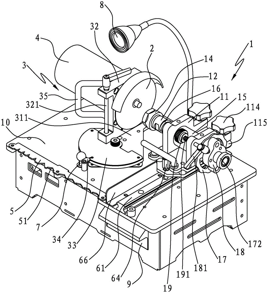
FIG. 1 is a schematic structural view of a drill grinder with multiple grinding effects according to the present invention;
FIG. 2 is a partially exploded view of the drill bit grinder of the present invention with multiple grinding effects;
FIG. 3 is an exploded view of the grinding wheel seat of the drill grinder with multiple grinding effects;
FIG. 4 is a partial cross-sectional view of a drill bit grinder having multiple grinding effects according to the present invention;
FIG. 5 is an exploded view of the drill rod collet of the drill bit grinder having multiple grinding effects according to the present invention;
FIG. 6 is a schematic front view of the angle dial of the drill bit grinder having various grinding effects according to the present invention;
FIG. 7 is a front view schematically showing an edge angle confirmation plate of the drill bit grinding machine having various grinding effects according to the present invention;
FIG. 8 is a front view of a first angle plate of the drill bit grinder having multiple grinding effects according to the present invention;
FIG. 9 is a schematic front view of a second angle plate of the drill bit grinder having multiple grinding effects according to the present invention;
FIG. 10 is a front view of a third angle plate of the drill bit grinder having multiple grinding effects according to the present invention;
FIG. 11 is a front view of a first type of dividing plate of the drill bit grinder having multiple grinding effects according to the present invention;
FIG. 12 is a schematic front view of a second type of dividing plate of the drill grinder having multiple grinding effects according to the present invention;
FIG. 13 is a front view of a third type of dividing plate of the drill bit grinder having multiple grinding effects according to the present invention;
FIG. 14 is a front view of a fourth dividing plate of the drill bit grinder having multiple grinding effects according to the present invention;
FIG. 15 is an exploded view of the combination of the index plate, the balance weight and the index plate locating pin of the drill bit grinding machine of the present invention;
fig. 16 is a schematic view of the combination of the dividing plate, the balance weight and the positioning pin of the dividing plate of the drill bit grinding machine of the present invention.
Description of the symbols
Workbench 10 drill rod barrel clamp 1 grinding wheel 2
Grinding wheel seat 3 motor 4 fixing seat 11
Front end locking nut 14 of drill bit sleeve 12 spring collet chuck 13 sleeve
Ball sleeve 15 bit shaft sleeve spring 16 supports riser 111
Supporting plate 311 of full-ball turntable 31, balancing weight 32
Bolt 312 bearing 313 of knife angle dial 33
Counterweight block positioning screw 321O-shaped silica gel ring 314
Angle pointer 34 spring 322 nut 323
Grinding wheel rotating handle 35 edge angle confirmation board 5
Blade angle confirmation groove 51 angle plate 17 angle plate rotation stopper pin 171
Sleeve rear lock nut 172 angle groove 173 index plate 18
Indexing plate positioning pin 181, positioning pin hole 182 and fine adjustment screw rod 19
Fine-tuning screw spring 191, slide rail 61, slide block 62, slide groove 63
Positioning screw 64 positioning slot 611 drill bit rod collet handle 65
Baffle 66 fixed length gag lever post 7 flat plate 112
Boss 113 and lock bolt 114 hold down washer 115
8 drawer 9 through grooves 183 of illuminating lamp
The counterbalance 184 abuts the groove 186 against the surface 185.
Detailed Description
In order to further explain the technical solution of the present invention, the present invention is explained in detail by the following embodiments.
Referring to fig. 1 to 14, the present invention discloses a drill grinder with multiple grinding effects, which comprises a worktable 10, and a drill rod collet 1, a grinding wheel 2, a grinding wheel seat 3 and a motor 4 which are arranged on the worktable 10;
the drill bit collet 1 is provided with a fixed seat 11, a drill bit sleeve 12 arranged on the fixed seat 11, a spring collet 13, a sleeve front end locking nut 14, a ball sleeve 15, a drill bit sleeve spring 16, an angle plate 17, an angle plate rotation limiting pin 171, a sleeve rear end locking nut 172, an indexing plate 18, an indexing plate positioning pin 181, a fine adjustment screw 19 and a fine adjustment screw spring 191; the fixed seat 11 is provided with two supporting vertical plates 111 for erecting a ball sleeve 15, the drill bit rod sleeve 12 penetrates through the ball sleeve 15, and the front end and the rear end of the drill bit rod sleeve respectively extend out of the two supporting vertical plates 111; the collet chuck 13 is assembled in the front end of the drill bit sleeve 12, and the sleeve front end locking nut 14 is locked at the front end of the drill bit sleeve 12 to limit the collet chuck 13 from being pulled out of the drill bit sleeve 12; the drill bit rod sleeve spring 16 is sleeved outside the drill bit rod sleeve 12, and two ends of the drill bit rod sleeve spring 16 respectively abut against the locking nut 14 at the front end of the sleeve and the supporting vertical plate 111;
the angle plate 17 is sleeved at the rear end of the drill rod sleeve 12, and the sleeve rear end locking nut 172 is locked at the rear end of the drill rod sleeve 12 to limit the angle plate 17 to be separated from the drill rod sleeve 12; the angle plate 17 is provided with a first through hole for the drill rod sleeve 12 to pass through and at least two angle grooves 173 with the same radian as the drill bit blade face, one end of the angle plate rotating limiting pin 171 is locked on the supporting vertical plate 111, and the other end is inserted into one of the angle grooves 173; in the grinding process, the drill bit rod sleeve is rotated, so that the angle plate rotates the limiting pin to reciprocate in the angle groove, and the drill bit can repeatedly rotate along the rotation angle of the angle groove to finish grinding of the cambered surface blade;
the dividing plate 18 is provided with a second through hole for the drill rod sleeve 12 to pass through, and a positioning pin hole 182 extending from the outer wall of the dividing plate 18 to the center of the second through hole, the dividing plate 18 is sleeved on the drill rod sleeve 12 and is positioned between the angle plate 17 and the sleeve rear end locking nut 172; the indexing plate positioning pin 181 penetrates through the positioning pin hole 182 and is rotated to abut against the outer wall of the drill rod sleeve 12; the relative positions of the indexing plate 18 and the bit sleeve 12 may be limited so that the length of the bit projecting beyond the bit sleeve 12 is consistent, thereby maintaining a consistent depth of cut for each blade;
the fine adjustment screw spring 191 is sleeved on the fine adjustment screw 19, and one end of the fine adjustment screw 19 is locked on the support vertical plate 111 and abuts against one side of the angle plate 17; before or after grinding, the fine adjustment screw 19 can be rotated clockwise, the fine adjustment screw 19 compresses a fine adjustment screw spring 191 and pushes an angle plate 17 to move backwards, the drill bit rod sleeve 12 moves backwards to compress a drill bit rod sleeve spring 16 and can drive the drill bit to move backwards so as to push the cutting edge of the drill bit away from the grinding wheel surface; when grinding is required, the fine adjustment screw rod 19 can be rotated anticlockwise, the fine adjustment screw rod 19 can be driven to move forwards by the elastic force of the fine adjustment screw rod spring 191, the angle plate 17 is not abutted by the fine adjustment screw rod 19, and the drill bit rod sleeve 12 can be driven to move forwards by the elastic force of the drill bit rod sleeve spring 16, so that the cutting edge of the drill bit slowly approaches the grinding wheel surface to start grinding the cutting edge;
the grinding wheel seat 3 is provided with a full ball turntable 31 rotationally pivoted with the workbench 10 and a balancing weight 32 arranged on the full ball turntable 31, the motor 4 is arranged on one side of the balancing weight 32, an output shaft of the motor 4 extends out of the other side of the balancing weight 32, and the grinding wheel 2 is arranged at the end part of the output shaft; a supporting plate 311 is arranged on the full-ball turntable 31, a cutting edge angle dial 33 is arranged on the supporting plate 311, the balancing weight 32 and the cutting edge angle dial 33 are arranged on the supporting plate 311 in a staggered mode, the circle center of the cutting edge angle dial 33 and the center of the full-ball turntable 31 are rotatably pivoted on the workbench 10 through a bolt 312 and a bearing 313, and one end of the balancing weight 32 is locked on the workbench 10 through a balancing weight positioning screw 321;
when the drill bit grinding machine with multiple grinding effects is used for grinding drill bits, an operator firstly confirms the cutting edge angle of the drill bit and rotates the balancing weight 32 to adjust the included angle between the grinding wheel 2 and the drill bit; selecting an adaptive collet chuck 13 according to the rod diameter of the drill bit and installing the collet chuck into a drill bit sleeve 12; a drill bit to be ground is loaded on a drill bit collet chuck 12 through a collet chuck 13, and then a locking nut 14 at the front end of a sleeve is locked; the angle plate 17 and the dividing plate 18 are respectively selected according to the radian and the number of the blade surfaces of the blades of the drill bit to be ground, the angle plate rotation limiting pin 171 is inserted into one angle groove 173, and the dividing plate positioning pin 181 is locked; when grinding a straight-edged drill bit, the fine adjustment screw 19 can be rotated clockwise to push the cutting edge of the drill bit away from the grinding wheel face; the grinding wheel 2 can be driven to rotate by turning on a switch of the motor 4; then, the fine adjustment screw rod 19 is rotated anticlockwise, so that the cutting edge of the drill bit slowly approaches to the grinding wheel surface to start grinding, and the grinding of the straight cutting edge surface is finished; when grinding a plurality of straight facet edges, the index plate 18 can be pulled outward and rotated; then the cutting edge of the drill bit slowly approaches the grinding wheel surface to start grinding, and grinding of the other cutting edge is completed; when the cambered surface edge drill bit is ground, the fine adjustment screw rod 19 can be rotated clockwise to push the edge of the drill bit away from the grinding wheel surface; the grinding wheel 2 can be driven to rotate by turning on a switch of the motor 4; then, the fine adjustment screw 19 is rotated counterclockwise to enable the cutting edge of the drill bit to slowly approach the grinding wheel surface to start grinding, the indexing plate 18 is rotated to enable the angle plate rotation limiting pin 171 to reciprocate in the angle groove 173, and the drill bit can rotate along the angle groove 173 by a rotation angle to finish grinding of the cambered surface cutting edge; when grinding a plurality of cambered-surface-edge blades, the dividing plate 18 is pulled outwards and rotated, the angle plate rotation limiting pin 171 is inserted into the other angle groove 173, and the angle plate rotation limiting pin 171 repeatedly rotates the dividing plate 18 up and down along the angle groove 173 to finish grinding the other blade; sequentially grinding all the cutting edges, and finally rotating the fine adjustment screw rod 19 clockwise to push the cutting edges of the drill away from the grinding wheel surface; turning off the motor 4, stopping the grinding wheel from rotating, and finishing grinding; the utility model can grind straight blade face drill bits, arc blade face drill bits and different numbers of blade bit bits, and the blade angle grinding precision of the drill bits is high, the operation is simple and easy to learn, the grinding efficiency is improved, and the grinding machine has simple and compact structure and low production cost; the weight balancing block can weigh 2.6 jin and can effectively play a role in damping; a switch electrically connected with the motor is arranged on the workbench 10; the collet chuck is a common accessory in the market, is low in price and is convenient to be equipped with accessories.
The utility model discloses drill bit grinds the operation method when the straight face cutting edge of two sword drill bits:
1. confirming the cutting edge angle of the drill to be ground on a cutting edge angle confirmation plate;
2. holding a grinding wheel rotating handle and rotating a grinding wheel seat according to the angle of the cutting edge, pointing an angle pointer to a corresponding angle scale on the cutting edge angle dial, and locking a balancing weight positioning bolt to adjust an included angle between the grinding wheel and a drill bit rod barrel clamp;
3. selecting an adaptive spring cartridge clip according to the rod diameter of the drill bit and installing the spring cartridge clip into a drill bit rod sleeve; a drill bit to be ground is arranged on a drill bit rod collet chuck through a collet chuck;
4. pulling up the fixed-length limiting rod, and adjusting the length of the drill bit extending out of the drill bit sleeve;
5. holding a drill rod barrel clamp handle to push the fixed seat to slide on the sliding rail, so that a space is reserved between the drill bit and the grinding surface of the grinding wheel, and locking a positioning screw to clamp the drill rod barrel on the workbench;
6. rotating the fine adjustment screw rod clockwise to push the cutting edge of the drill bit away from the grinding wheel surface; the grinding wheel can be driven to rotate by opening a motor switch; rotating the fine adjustment screw rod anticlockwise to enable the cutting edge of the drill bit to slowly approach the grinding wheel surface to start grinding, and finishing grinding of the cutting edge;
7. when another cutting edge needs to be ground, the dividing plate can be pulled out and rotated for 180 degrees; then the cutting edge of the drill bit slowly approaches the grinding wheel surface to start grinding, and grinding of the other cutting edge is completed;
8. sequentially grinding all the cutting edges, and finally, clockwise rotating the fine adjustment screw to push the cutting edges of the drill away from the grinding wheel surface; and (5) turning off the motor, stopping the rotation of the grinding wheel and finishing the grinding of the straight-face blade.
The utility model discloses drill bit grinds operation method when the cambered surface sword of two sword drill bits:
1. confirming the cutting edge angle of the drill to be ground on a cutting edge angle confirmation plate;
2. holding a grinding wheel rotating handle and rotating a grinding wheel seat according to the angle of the cutting edge, pointing an angle pointer to a corresponding angle scale on the cutting edge angle dial, and locking a balancing weight positioning bolt to adjust an included angle between the grinding wheel and a drill bit rod barrel clamp;
3. selecting an adaptive spring cartridge clip according to the rod diameter of the drill bit and installing the spring cartridge clip into a drill bit rod sleeve; a drill bit to be ground is arranged on a drill bit rod collet chuck through a collet chuck;
4. pulling up the fixed-length limiting rod, and adjusting the length of the drill bit extending out of the drill bit sleeve;
5. holding a drill rod barrel clamp handle to push the fixed seat to slide on the sliding rail, so that a space is reserved between the drill bit and the grinding surface of the grinding wheel, and locking a positioning screw to clamp the drill rod barrel on the workbench;
6. selecting an angle plate and an indexing plate respectively according to the radian and the number of blade surfaces of the blades of the drill bit to be ground, inserting a rotating limiting pin of the angle plate into one angle groove, and locking a positioning pin of the indexing plate;
7. rotating the fine adjustment screw rod clockwise to push the cutting edge of the drill bit away from the grinding wheel surface; the grinding wheel can be driven to rotate by opening a motor switch; the fine adjustment screw rod is rotated anticlockwise, so that the cutting edge of the drill bit slowly approaches to the grinding wheel surface to start grinding, the indexing plate is rotated to enable the angle plate to rotate the limiting pin to reciprocate in the angle groove, and the drill bit can repeatedly rotate along the rotation angle of the angle groove to finish grinding of the cutting edge;
8. the dividing plate is pulled out outwards and rotated for 180 degrees, the angle plate rotation limiting pin is inserted into the other angle groove, and the angle plate rotation limiting pin repeatedly rotates the dividing plate up and down along the angle groove to finish grinding of the other cutting edge;
9. sequentially grinding all the cutting edges, and finally, clockwise rotating the fine adjustment screw to push the cutting edges of the drill away from the grinding wheel surface; and (5) turning off the motor, stopping the grinding wheel and finishing grinding.
The utility model can be provided with different angle plates, each angle plate is provided with an angle groove with different rotation angles, so that drill bits or cutters with different arc blade angle surfaces can be ground by replacing different angle plates; for example, when a 30 °, 45 ° or 60 ° arc blade facet needs to be ground, an angle plate with a rotation angle of the angle groove of 30 °, 45 ° or 60 ° may be selected; furthermore, the utility model discloses can be equipped with different graduated plates, every graduated plate circumference evenly is provided with two, three, four or six location pinhole to can grind the drill bit or the cutter of different quantity cutting edges through changing different angle boards.
The bead-filled turntable 31 of the utility model is provided with an O-shaped silica gel ring 314 outside the bead, which can prevent the lubricating oil from leaking and prevent the grinding scraps from falling into the bead to cause unsmooth rotation; a copper sleeve for limiting the parallel rotation of the two upper and lower turnplate pieces is arranged between the two upper and lower turnplate pieces of the full-ball turnplate 314; the full ball turntable 31 can rotate more smoothly.
An angle pointer 34 is arranged on one side of the knife edge angle dial 33, and a straight line where the center of the angle pointer 34 and the circle center of the knife edge angle dial 33 are located is vertical to the axis of the drill bit sleeve 12; the straight line where the positioning bolt 321 and the bolt 312 are located is parallel to the axis of the drill rod sleeve 12; the included angle between the grinding wheel 2 and the drill bit sleeve 12 is convenient to adjust; moreover, the grinding wheel 2 and the full ball turntable 31 are eccentrically arranged, when the full ball turntable 31 is rotated, the adjustable range of the distance between the grinding wheel 2 and the drill bit rod sleeve 12 is larger, and drill bits with different lengths can be ground.
In the utility model, the bottom end of the positioning bolt 321 of the balancing weight is sleeved with a spring 322 and is in threaded connection with the bottom plate of the workbench 10 through a nut 323, and the balancing weight 31 can be firmly locked on the workbench 10; and one side of the balancing weight 32 is provided with a grinding wheel rotating handle 35; the operator holds the wheel turning handle 35 to facilitate turning the wheel head 3.
The range of the rod diameter of the drill bit to be ground of the utility model is 3-20mm, and the drill bit rod of each rod diameter is a collet chuck 13 with the same aperture; the spring collet chuck 13 with different apertures can be used for clamping drill bits with different rod diameters, so that the drill bits with different rod diameters can be ground, and the applicability is stronger.
The utility model discloses a 10 side of workstation is provided with sword angle and confirms board 5, be provided with the sword angle of a plurality of different angles on sword angle and confirm the groove 51 on board 5; the knife edge angle can be conveniently confirmed by operators, and the grinding is more convenient.
The angle range of the blade surface of the drill bit to be ground of the utility model is 30-150 degrees, and the rotation angle of the angle groove of the angle plate is 30-150 degrees.
The dividing plate 18 of the present invention is provided with a through groove 183 communicated with the positioning pin hole 182, a balance block 184 is arranged in the through groove 183, the balance block 184 is provided with a butting surface 185 tightly butted against the outer wall of the drill rod sleeve and a butting groove 186 for butting against the dividing plate positioning pin 181, and the central line of the through groove 183, the central line of the balance block 184 and the central line of the dividing plate positioning pin 181 are located on the same straight line; the positioning pin 181 of the indexing plate is tightly pressed against the outer wall of the bit sleeve 12 through the balance block 184 to limit the relative rotation between the indexing plate 18 and the bit sleeve 12, so that when the indexing plate is locked, the indexing plate is not biased to a single side due to the clearance between the indexing plate 18 and the bit sleeve 12, thereby influencing the clearance between the angle plate 17 locked on the indexing plate 18 and the tail end of the bit sleeve 12.
The circumference of the dividing plate 18 of the utility model is evenly provided with two, three, four or six positioning pin holes 182; the indexing plate locating pins 181 and locating pin holes 182 cooperate to uniformly grind each blade.
The utility model discloses a sliding mechanism is arranged between the drill rod collet chuck 1 and the workbench 10, the sliding mechanism is provided with a sliding rail 61 locked on the workbench 10 and a sliding block 62 locked below the fixed seat 11, the sliding block 62 is provided with a sliding groove 63 reversely buckled on the sliding rail 61; the sliding mechanism can adjust the position relation between the drill rod collet 1 and the grinding wheel 2, so that the adjustment position between the drill and the grinding wheel 2 is wider and the use is more convenient; the fixed seat 11 is provided with a screw hole 63, and a positioning screw rod 64 is locked in the screw hole 63 and the end part of the positioning screw rod abuts against the top surface of the slide rail 61; the positioning screw 64 can fix the fixed seat 11 on the working platform 10.
The top surface of the slide rail 61 of the present invention is provided with a plurality of positioning grooves 611 for the positioning screws 64 to push against, and when the positioning screws 64 push against the positioning grooves 611, the fixing structure of the slide block 62 and the slide rail 61 can be firmer; the fixed seat 11 is provided with a drill rod collet chuck handle 65 for pushing the drill rod collet chuck 1 to slide on the slide rail 61; the drill rod collet 1 is more convenient to push.
The utility model is provided with a baffle 66 which resists grinding waste on one side of the slide rail 61 close to the grinding wheel 2; the grinding waste is prevented from falling between the sliding rail 61 and the sliding block 62 to influence the normal sliding motion of the sliding rail 61 and the sliding block 62.
The drill bit grinding machine with multiple grinding effects further comprises a fixed length limiting rod 7 for limiting the length of the drill bit extending out of the drill bit collet chuck 1, the workbench 10 is provided with a through hole for the fixed length limiting rod 7 to pass through, the workbench 10 is provided with a first magnet below the through hole, and the bottom end of the fixed length limiting rod 7 is provided with a second magnet which is magnetically attracted with the first magnet; the top end of the fixed-length limiting rod 7 is provided with a red ball part; the fixed-length limiting rod 7 is positioned on one side of the angle pointer 34; when the length of the drill bit extending out of the drill bit collet chuck 1 is limited, the fixed-length limiting rod 7 can be pulled up, the second magnet at the bottom end of the fixed-length limiting rod 7 is attracted to the first magnet under the workbench 10 in a magnetic mode, the fixed-length limiting rod 7 can be kept to stand on the workbench 10, and the length of the drill bit extending out of the drill bit collet chuck 12 can be limited conveniently; when the fixed-length limiting rod 7 is not used, the fixed-length limiting rod 7 can be pressed, so that the first magnet and the second magnet are separated, and the fixed-length limiting rod 7 falls into the workbench 10.
The fixing seat 11 of the utility model is provided with a square handle pressing structure for clamping a square handle drill rod, the square handle pressing structure is provided with a flat plate 112 extending outwards from the bottom of the fixing seat 11, two convex parts 113 extending outwards from two supporting vertical plates 111, two locking bolts 114 and two pressing gaskets 115, each convex part 113 is provided with a lock hole, the locking bolt 114 is locked in the lock hole, and the pressing gasket 115 is fixed on the locking bolt 114 and penetrates out of one end of the lock hole; the square shank drill rod is placed on the flat plate 112, the locking bolt 114 is rotated, so that the pressing gasket 115 firmly presses the square shank drill rod on the fixing seat 11, the square shank drill can be ground, and the application range is wider.
The drill bit grinder with multiple grinding effects of the utility model also comprises an illuminating lamp 8 arranged beside the drill bit collet chuck 1; the illumination is improved, and the grinding is more convenient.
The drill bit grinding machine with multiple grinding effects is provided with the drawer 9 with different collet chucks 13, the drill bit grinding machine with multiple grinding effects can be equipped with different collet chucks 3, and the drawer can conveniently store the collet chucks 13.
The utility model discloses a emery wheel 2 is the emery wheel for the jade, and grinding area is bigger, and long service life, low price reduce the utility model discloses the multiple drill bit of grinding the effect grinds machine's manufacturing cost.
The above embodiments and drawings do not limit the form and style of the present invention, and any suitable changes or modifications made by those skilled in the art should not be considered as departing from the scope of the present invention.