CN214970845U - Drainage tube for infection of oral cavity, jaw and facial space - Google Patents
Drainage tube for infection of oral cavity, jaw and facial space Download PDFInfo
- Publication number
- CN214970845U CN214970845U CN202120847819.7U CN202120847819U CN214970845U CN 214970845 U CN214970845 U CN 214970845U CN 202120847819 U CN202120847819 U CN 202120847819U CN 214970845 U CN214970845 U CN 214970845U
- Authority
- CN
- China
- Prior art keywords
- drainage tube
- support
- pus
- drainage
- cavity
- Prior art date
- Legal status (The legal status is an assumption and is not a legal conclusion. Google has not performed a legal analysis and makes no representation as to the accuracy of the status listed.)
- Expired - Fee Related
Links
Images



Landscapes
- Media Introduction/Drainage Providing Device (AREA)
- External Artificial Organs (AREA)
Abstract
The utility model relates to a drainage tube for infection of oral cavity jaw face clearance. Drainage tube for infection of oral cavity maxillofacial space includes: a central body having an insertion end as a front end, the central body extending in a front-rear direction; the supporting parts are arranged on the central body, a plurality of supporting parts are arranged at intervals along the circumferential direction of the central body, and a drainage groove is formed between every two adjacent supporting parts; the radial dimension of the front portion of the support member is smaller than the radial dimension of the rear portion thereof. After the drainage operation, in the early stage of healing of the pus cavity, the volume of the pus cavity is larger, more pus is also contained, and the whole drainage tube is inserted into the pus cavity, so that the supporting part is matched with the pus cavity, and the pus flows out of the drainage groove; in the middle and later stages of healing of the pus cavity, the cavity of the pus cavity is smaller, the pus is less, and a part of the drainage tube can be pulled out, so that the supporting component can still be matched with the pus cavity, the drainage tube does not need to be replaced, the drainage can be continued, and the drainage is convenient.
Description
Technical Field
The utility model relates to a drainage tube for infection of oral cavity jaw face clearance.
Background
The oral cavity and maxillofacial region is positioned at the starting ends of the digestive tract and the respiratory tract, and is directly communicated with the outside through the oral cavity and the nasal cavity, and the anatomical structure, the temperature and the humidity are all suitable for breeding and propagating bacteria, so that a large amount of microorganisms exist under normal conditions. When the oral cavity, jaw and face are affected by trauma, low resistance of the whole body and other factors, the occurrence of gap infection is easy to happen.
When the oral cavity maxillofacial region gap infects, the surgery treatment means is mainly abscess incision drainage, and after the abscess incision drainage, guarantees smooth abscess drainage through keeping somewhere the drainage tube. The patent application with the application publication number of CN112023137A discloses a drainage tube, which comprises a central body, a round blunt shape, three supporting parts and drainage holes, wherein the central body is a hollow cylindrical pipeline, the round blunt shape is arranged at the top end of the central body, the supporting parts are fixedly connected to the surface of the central body, the three supporting parts are arranged at intervals, two adjacent supporting parts and the central body jointly enclose a drainage groove, and the bottom of the drainage groove is provided with the drainage holes.
Although drainage to pus is realized by the drainage tube, the pus cavity is gradually reduced in the process of healing gradually, and the supporting parts of the drainage tube are consistent along the radial dimension of the drainage tube, so that the drainage tube can be only suitable for a certain stage in the healing process of the pus cavity, and therefore, the drainage tube with different radial dimensions needs to be replaced to realize drainage of pus in different stages.
SUMMERY OF THE UTILITY MODEL
An object of the utility model is to provide a drainage tube is used in facial clearance infection of oral cavity jaw to solve among the prior art pus chamber and need change different radial dimension's drainage tube and just can realize the technical problem to the pus drainage of different stages at the in-process that heals gradually.
In order to realize the purpose, the utility model discloses drainage tube for infection of oral cavity maxillofacial region clearance's technical scheme is:
drainage tube for infection of oral cavity maxillofacial space includes:
a central body having an insertion end as a front end, the central body extending in a front-rear direction;
the supporting parts are arranged on the central body, a plurality of supporting parts are arranged at intervals along the circumferential direction of the central body, and a drainage groove is formed between every two adjacent supporting parts;
the radial dimension of the front portion of the support member is smaller than the radial dimension of the rear portion thereof.
The beneficial effects are that: after the drainage operation, in the early stage of healing of the pus cavity, the volume of the pus cavity is larger, more pus is also contained, and the whole drainage tube is inserted into the pus cavity, so that the supporting part is matched with the pus cavity, and the pus flows out of the drainage groove; in the middle and later stages of healing of the pus cavity, the cavity of the pus cavity is smaller, the pus is less, and a part of the drainage tube can be pulled out, so that the supporting component can still be matched with the pus cavity, the drainage tube does not need to be replaced, the drainage can be continued, and the drainage is convenient.
Further, the support component comprises at least two support sections, all the support sections are arranged at intervals in the front-back direction, and the radial dimension of the front support section in every two adjacent support sections is smaller than that of the rear support section.
Further, the radial dimension of each support section is gradually increased from the front to the back.
The beneficial effects are that: design like this for the in-process that the drainage tube inserted the pustule cavity struts the pustule cavity gradually, is favorable to not only the pus to flow out, under the effect in pustule cavity, can guarantee the stability of drainage tube in the pustule cavity moreover.
Furthermore, an inclined transition section is arranged between two adjacent support sections.
The beneficial effects are that: through setting up the slope changeover portion, be favorable to the drainage tube to insert in the pustule.
Further, the radial dimension of the support member is gradually increased from the front to the rear.
The beneficial effects are that: design like this for the in-process that the drainage tube inserted the pustule cavity struts the pustule cavity gradually, is favorable to not only the pus to flow out, under the effect in pustule cavity, can guarantee the stability of drainage tube in the pustule cavity moreover.
Furthermore, the central body is provided with a central hole, the front part of the bottom of the drainage groove is provided with a communication hole, and the communication hole is communicated with the central hole and the drainage groove.
The beneficial effects are that: by the design, the drainage tube can drain the pus and can wash the pus.
Furthermore, the tail end of the central body is provided with a connector which is used for connecting an injector or a suction apparatus.
The beneficial effects are that: the connection of the central body and the injector or the aspirator is facilitated by the arrangement of the connector.
Furthermore, the supporting parts are supporting wings, and an included angle between every two adjacent supporting wings is an obtuse angle.
The beneficial effects are that: therefore, the cross section of the drainage groove is large in size, and the discharge of pus is facilitated.
Furthermore, the number of the support wings is four, two support wings form one support wing group, and the size of one support wing in the two support wing groups is larger than that of the other support wing group, so that the cross section of the drainage tube is in a butterfly structure.
The beneficial effects are that: the top points of the four supporting wings form a trapezoidal structure after being connected, and the trapezoidal structure is consistent with the size of the pus cavity, so that the drainage tube cannot rotate in the pus cavity, and the stability of the drainage tube in the pus cavity is ensured.
Furthermore, the front end of the supporting component is of an arc-shaped structure.
The beneficial effects are that: thus being beneficial to inserting the drainage tube into the inner part of the pustule cavity and avoiding the bleeding caused by puncturing the blood vessel of the wound surface.
Drawings
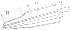
FIG. 1 is a schematic structural view of an embodiment 1 of a drainage tube for infection of the oral, maxillofacial space of the present invention;
FIG. 2 is a schematic view of the structure of FIG. 1 from another perspective;
fig. 3 is a sectional view at the communication hole in fig. 2;
FIG. 4 is a schematic structural view of embodiment 2 of the drainage tube for infection of the oral, maxillofacial space of the present invention;
in fig. 1 to 3: 11. a communicating hole; 12. a front support section; 13. a sloped transition section; 14. a drainage groove; 15. a rear support section; 16. a support wing; 17. a connector; 18. a central bore;
in fig. 4: 21. a communicating hole; 22. a drainage groove; 23. a support wing; 24. a central body; 25. a connector; 26. a central bore.
Detailed Description
In order to make the objects, technical solutions and advantages of the present invention more clearly understood, the present invention is further described in detail below with reference to the accompanying drawings and embodiments. It should be understood that the specific embodiments described herein are for purposes of illustration only and are not intended to limit the invention, i.e., the described embodiments are only some, but not all embodiments of the invention. The components of embodiments of the present invention, as generally described and illustrated in the figures herein, may be arranged and designed in a wide variety of different configurations.
Thus, the following detailed description of the embodiments of the present invention, presented in the accompanying drawings, is not intended to limit the scope of the invention, as claimed, but is merely representative of selected embodiments of the invention. Based on the embodiment of the present invention, all other embodiments obtained by the person skilled in the art without creative work belong to the protection scope of the present invention.
It is noted that relational terms such as "first" and "second," and the like, may be used solely to distinguish one entity or action from another entity or action without necessarily requiring or implying any actual such relationship or order between such entities or actions. Also, the terms "comprises," "comprising," or any other variation thereof, are intended to cover a non-exclusive inclusion, such that a process, method, article, or apparatus that comprises a list of elements does not include only those elements but may include other elements not expressly listed or inherent to such process, method, article, or apparatus. Without further limitation, an element defined by the phrase "comprising an … …" does not exclude the presence of other identical elements in a process, method, article, or apparatus that comprises the element. Furthermore, the terms "upper" and "lower" are based on the orientation and positional relationship shown in the drawings and are only for convenience of description of the present invention, and do not indicate that the referred device or component must have a specific orientation, and thus, should not be construed as limiting the present invention.
The features and properties of the present invention are described in further detail below with reference to examples.
The utility model discloses oral cavity maxillofacial clearance infects embodiment 1 with drainage tube:
as shown in fig. 1 to 3, the drainage tube for infection in the oral cavity, maxillofacial space includes a central body, the central body extends along the front-back direction with the insertion end of the central body as the front end, the central body has a central hole 18, and the rear end of the central body has a connector 17, the connector 17 is convenient for connecting with an injector. Wherein, the front end of the central body is of a sealing structure, so as to prevent the washing liquid from washing the pus into deep healthy tissues to cause infection diffusion.
In this embodiment, the central body is integrally formed with four support wings 16, the four support wings 16 are arranged along the circumference of the central body at intervals, a drainage groove 14 is formed between two adjacent support wings 16, and the drainage groove 14 is used for discharging pus and flushing liquid. In other embodiments, the support wings are formed separately from the central body and then fixedly attached together.
In this embodiment, the front portion of drainage groove 14 tank bottom is equipped with intercommunicating pore 11, and intercommunicating pore 11 intercommunication centre bore 18 and drainage groove 14 after the syringe is connected on connector 17, send into the flush fluid in the centre bore 18 to flow out by intercommunicating pore 11 to wash the pus in the pus chamber, make the pus discharge from the pus chamber fast, realized the drainage to the pus like this promptly, realized the washing to the pus again. Wherein the cleaning solution is physiological saline, hydrogen peroxide, etc. In other embodiments, the connector can be connected with a suction apparatus to realize negative pressure drainage of the wound surface and fully suck out exuded liquid of the wound surface.
In this embodiment, the radial dimension of the front end of the support wing 16 is smaller than the radial dimension of the rear end of the support wing 16. Specifically, as shown in fig. 1 and 2, the support wing 16 includes two support sections, which are a front support section 12 and a rear support section 15, respectively, the front support section 12 and the rear support section 15 are arranged at intervals along the front-rear direction, and the radial dimension of the front support section 12 is smaller than that of the rear support section 15, so that the cross section of the drainage groove 14 at the front support section 12 is smaller, drainage is performed with less pus, the cross section of the drainage groove 14 at the rear support section 15 is larger, and drainage is performed with more pus.
In the early stage of healing of the pus cavity, the cavity of the pus cavity is large, and much pus is contained, so that the drainage tube can be inserted into the pus cavity until the rear support section 15 is positioned in the pus cavity, the volume of the pus cavity can be matched, and the pus can be quickly discharged; in the later stage of healing of the pus cavity, the cavity of the pus cavity is smaller, the pus is less, the rear support section 15 of the drainage tube can be pulled out, and only the front support section 12 is in the pus cavity, so that the front support section 12 is matched with the volume of the pus cavity, and the drainage tube does not need to be replaced. Wherein the rear support section 15 may be cut away in order to avoid affecting the patient's movement.
In this embodiment, the radial dimension of preceding support segment 12 and back support segment 15 is by preceding crescent respectively backward, designs like this for the drainage tube inserts the in-process in pustule chamber and struts the pustule chamber gradually, not only is favorable to the pus to flow out, moreover under the effect in pustule chamber, can guarantee the stability of drainage tube in the pustule chamber.
In this embodiment, an inclined transition section 13 is arranged between the front support section 12 and the rear support section 15, and the inclined transition section 13 is arranged to facilitate the insertion of the drainage tube into the pus cavity.
As shown in FIG. 3, the two support wings 16 form a support wing set, and the size of one support wing 16 in the two support wing sets is larger than that of the other support wing 16, so that the cross section of the drainage tube is in a butterfly structure, and thus the vertex of the four support wings form a trapezoid structure after being connected, which is consistent with the size of the pus cavity, so that the drainage tube cannot rotate in the pus cavity, and the stability of the drainage tube in the pus cavity is ensured. In other embodiments, the four support wings may be the same size.
In this embodiment, the included angle between two adjacent support wings 16 is an obtuse angle, so that the cross-sectional dimension of the drainage groove is large, and the drainage groove is favorable for flowing out pus. In this embodiment, the front end of the support wing 16 is arc-shaped, which is beneficial to inserting the drainage tube into the pus cavity and avoiding the bleeding caused by puncturing the blood vessel of the wound surface.
It should be noted that the drainage tube is made of a soft material, such as rubber, so as to avoid damage to the wound abscess.
At the drainage postoperative, the initial stage of pustule healing, the pustule is bulky, and the pus is also more, with the whole pus intracavity of inserting of drainage tube, the pus is flowed out by drainage groove 14, if need wash, then connect the syringe with the connector 17 of drainage tube, push the flush fluid in to centre bore 18 through the syringe to wash the pus in the pus intracavity, final pus and flush fluid flow out from drainage groove 14 together. In pustule healing later stage, the pustule cavity is less, and the pus is also less, can extract the back support section 15 of drainage tube, and only support section 12 is in the pustule intracavity before remaining for preceding support section 12 matches the volume in pustule, need not to change the drainage tube like this, just can continue the drainage, and is comparatively convenient. Wherein the rear support section 15 may be cut away in order to avoid affecting the patient's movement.
The utility model discloses oral cavity maxillofacial clearance infects embodiment 2 with drainage tube:
the present embodiment differs from embodiment 1 in that in embodiment 1, the support wing 16 includes two support sections, a front support section 12 and a rear support section 15, the front support section 12 and the rear support section 15 are arranged at intervals in the front-rear direction, and the radial dimension of the front support section 12 is smaller than that of the rear support section 15. In this embodiment, as shown in fig. 4, the draft tube includes a central body 24, four support wings 23 are provided on the central body 24, a drainage groove 22 is formed between two adjacent support wings 23, and a communication hole 21 is provided at the front of the bottom of the drainage groove 22; the central body 24 has a connector 25 at the rear end thereof, the connector 25 is used for connecting a syringe, the central body 24 further has a central hole 26, the central hole 26 is communicated with the drainage groove 22 through the communication hole 21, wherein the radial dimension of the support wings 23 is gradually increased from the front to the rear, and the drainage tube is adapted to the pus cavity in different healing periods by gradually pulling the drainage tube outwards.
The utility model discloses oral cavity maxillofacial clearance infects embodiment 3 with drainage tube:
the present embodiment is different from embodiment 1 in that in embodiment 1, the radial dimensions of the front support section 12 and the rear support section 15 are gradually increased from the front to the rear, respectively. In this embodiment, the radial dimension of the front support section is consistent from front to back, and the radial dimension of the rear support section is consistent from front to back.
The utility model discloses oral cavity maxillofacial clearance infects embodiment 4 with drainage tube:
the difference between this embodiment and embodiment 1 is that in embodiment 1, the central body has a central hole 18, the front part of the bottom of the drainage groove 14 is provided with a communication hole 11, and the communication hole 11 communicates the central hole 18 and the drainage groove 14, so that the drainage tube can realize drainage of pus and flushing of pus. In this embodiment, the central body does not have a central hole, the bottom of the drainage groove is not provided with a communication hole, and the drainage tube only plays a drainage role.
The utility model discloses oral cavity maxillofacial clearance infects embodiment 5 with drainage tube:
the present embodiment is different from embodiment 1 in that in embodiment 1, the supporting parts are supporting wings 16, and the included angle between two adjacent supporting wings 16 is an obtuse angle. In this embodiment, the support member is the support member disclosed in application publication No. CN112023137A, and the radial dimension of the support member gradually increases from the front to the rear.
The above description is only for the preferred embodiment of the present invention, and the present invention is not limited thereto, the protection scope of the present invention is defined by the claims, and all structural changes equivalent to the contents of the description and drawings of the present invention should be included in the protection scope of the present invention.
Claims (10)
1. Drainage tube for infection of oral cavity maxillofacial space includes:
a central body having an insertion end as a front end, the central body extending in a front-rear direction;
the supporting parts are arranged on the central body, a plurality of supporting parts are arranged at intervals along the circumferential direction of the central body, and a drainage groove is formed between every two adjacent supporting parts;
wherein the radial dimension of the front end of the support member is smaller than the radial dimension of the rear end thereof.
2. The drainage tube for oromandibular-facial gap infection according to claim 1, wherein the support member includes at least two support sections, all of which are spaced apart in the anterior-posterior direction, a radial dimension of an anterior support section of adjacent two support sections being smaller than a radial dimension of a posterior support section.
3. The drainage tube for oromaxillofacial space infection according to claim 2, wherein the radial dimension of each support section is gradually increased from the front to the rear.
4. The drainage tube for oromaxillofacial space infection according to claim 2, wherein an inclined transition section is provided between two adjacent support sections.
5. The drainage tube for oromaxillofacial space infection according to claim 1, wherein a radial dimension of said support member is gradually increased from a front side to a rear side.
6. The drainage tube for oromaxillofacial space infection according to any one of claims 1 to 5, wherein said central body has a central hole, and the front part of the bottom of the drainage groove is provided with a communication hole communicating the central hole and the drainage groove.
7. The drainage tube for infection of the oral, maxillofacial space of claim 6, wherein the central body has a connector at its end for connecting an injector or a suction apparatus.
8. The drainage tube for infection of the oral maxillofacial space according to any one of claims 1 to 5, wherein the support members are support wings, and an included angle between two adjacent support wings is an obtuse angle.
9. The drainage tube for oromandibular facial space infection according to claim 8, wherein the number of said support wings is four, two support wings form one support wing group, and one of the two support wing groups has a larger size than the other support wing group to make the cross section of the drainage tube in a butterfly configuration.
10. The drainage tube for oromaxillofacial space infection according to any one of claims 1 to 5, wherein a front end of the support member has an arc-shaped configuration.
Priority Applications (1)
| Application Number | Priority Date | Filing Date | Title |
|---|---|---|---|
| CN202120847819.7U CN214970845U (en) | 2021-04-23 | 2021-04-23 | Drainage tube for infection of oral cavity, jaw and facial space |
Applications Claiming Priority (1)
| Application Number | Priority Date | Filing Date | Title |
|---|---|---|---|
| CN202120847819.7U CN214970845U (en) | 2021-04-23 | 2021-04-23 | Drainage tube for infection of oral cavity, jaw and facial space |
Publications (1)
| Publication Number | Publication Date |
|---|---|
| CN214970845U true CN214970845U (en) | 2021-12-03 |
Family
ID=79095419
Family Applications (1)
| Application Number | Title | Priority Date | Filing Date |
|---|---|---|---|
| CN202120847819.7U Expired - Fee Related CN214970845U (en) | 2021-04-23 | 2021-04-23 | Drainage tube for infection of oral cavity, jaw and facial space |
Country Status (1)
| Country | Link |
|---|---|
| CN (1) | CN214970845U (en) |
-
2021
- 2021-04-23 CN CN202120847819.7U patent/CN214970845U/en not_active Expired - Fee Related
Similar Documents
| Publication | Publication Date | Title |
|---|---|---|
| US20260053531A1 (en) | Postpartum uterine hemorrhage device | |
| CN103028187B (en) | There is the conduit of tapered surface | |
| WO2014014644A1 (en) | Soft tip cannula | |
| JP2010005282A (en) | Medical drain tube | |
| CN113171536B (en) | Drainage tube for infection of oral cavity, jaw and face gaps | |
| CN106492325A (en) | A kind of drainage tube | |
| CN108355225A (en) | A kind of ductus venosus and preparation method thereof with the dual anti-valve that backflows | |
| CN202061215U (en) | Double-set abdominal cavity irrigation drainage tube with plug | |
| CN214970845U (en) | Drainage tube for infection of oral cavity, jaw and facial space | |
| CN204364625U (en) | The disposable three chamber blood-stopping urinary catheters of modified form | |
| CN219374864U (en) | An anti-clogging uterine hemostasis device | |
| TWM551482U (en) | Catheter | |
| CN208693997U (en) | A drainage tube that prevents damage to surrounding tissue when pulled out | |
| CN215426865U (en) | Anti-displacement and anti-leakage urine-flushing catheter | |
| CN206138563U (en) | Medical double cannula device | |
| CN105854176B (en) | Conversion plug-in components of peritoneal cavity drainage tube | |
| CN108295354A (en) | A kind of suction type orthopedic drainage tube | |
| CN212281492U (en) | Three-sac anorectal compression hemostasis drainage device | |
| CN211434648U (en) | Single-channel arterial cannula for left heart assistance | |
| JP4185626B2 (en) | Medical drain tube | |
| CN216124861U (en) | Superficial small intestine fistula integrated treatment device | |
| US20220331568A1 (en) | Neovaginal stent system | |
| CN222899820U (en) | A pericardial drainage tube | |
| CN221808298U (en) | Anti-blocking antibacterial catheter | |
| CN221431719U (en) | Prevent floating peritoneal dialysis tube |
Legal Events
| Date | Code | Title | Description |
|---|---|---|---|
| GR01 | Patent grant | ||
| GR01 | Patent grant | ||
| CF01 | Termination of patent right due to non-payment of annual fee |
Granted publication date: 20211203 |