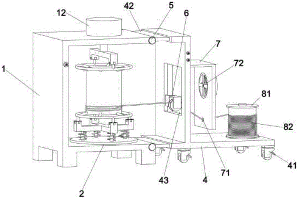
Tensile interval adjusting device of cable wire drawing machine
Technical Field
The utility model relates to a wire drawing machine technical field specifically is a tensile interval adjusting device of cable wire drawing machine.
Background
The cable is generally a cable similar to a rope formed by stranding a plurality of or a plurality of groups of wires, each group of wires are mutually insulated and are usually twisted around a center, a high-insulation covering layer is wrapped outside the whole cable, and a wire drawing machine is a mechanical device widely used in industrial application, is commonly used in the industries of mechanical manufacturing, hardware processing, petrochemical industry, plastics, bamboo and wood products, electric wires and cables and the like, and is particularly widely applied to cable production enterprises.
The metal material of raw and other materials needs to be subjected to wire drawing treatment in the cable production process, so that the diameter of the raw and other materials is reduced, the drawing distance of the conventional cable wire drawing machine is generally fixed, the drawing distance cannot be extended, and the applicability is poor.
SUMMERY OF THE UTILITY MODEL
An object of the utility model is to provide a tensile interval adjusting device of cable wire drawing machine to solve the problem that proposes among the above-mentioned background art.
In order to achieve the above object, the utility model provides a following technical scheme: a cable drawing machine stretching interval adjusting device comprises a left frame and a right frame, wherein sliding grooves are symmetrically formed in the left surface of the left frame, connecting plates are symmetrically and fixedly installed on the left surface of the right frame, the connecting plates are slidably installed in the sliding grooves, locking bolts are installed on the front surface and the rear surface of the left frame in a screwed mode and fix the connecting plates in the sliding grooves, a driving motor is fixedly installed on the upper surface of the left frame, the output end of the driving motor penetrates through the inner side wall of the left frame, a clamping device is rotatably installed between the output end of the driving motor and the lower surface of the inner cavity of the left frame, a winding roller is placed in the clamping device, universal wheels are fixedly installed on the lower surface of the right frame, an installation opening is formed in the right frame in a penetrating mode, a wire smoothing-out device is fixedly installed in the installation opening, and a fixing plate is fixedly installed on the right surface of the right frame, the outer surface of the fixing plate is provided with a wire transmission hole in a penetrating mode, the upper surface of the right frame is fixedly provided with a fixing column, the outer surface of the fixing column is rotatably provided with a second winding roller, a cable is connected between the second winding roller and the winding roller, and the cable penetrates through the wire transmission hole and the wire smoothing device.
Preferably, the equal fixed mounting in upper and lower surface of coiling cylinder has the spliced pole, the equal fixed mounting in outside surface of spliced pole has the cross fixture block, the trapping mechanism includes base and last locating piece, go up locating piece and driving motor's output fixed connection, the base rotates the inner chamber lower surface of installing at the left side frame, and the last fixed surface of base installs flexible post, the top fixed mounting of flexible post has down the locating piece, fixed mounting has the spring down between locating piece and the base, flexible post is located spring inner ring department, the cross draw-in groove has all been seted up to the upper surface of locating piece and the lower surface of last locating piece down, the cross fixture block joint is installed in the cross draw-in groove.
Preferably, the wire smoothing device comprises a fixing rod which is fixedly installed in the installation opening, a guide cylinder is arranged on the outer surface of the fixing rod, a wire roller is fixedly installed on the front surface of the guide cylinder, and the inner side wall of the wire roller is attached to the outer surface of the cable.
Preferably, a heat dissipation fan is embedded in the right surface of the fixing plate, and the heat dissipation direction of the heat dissipation fan corresponds to the positions of the mounting port and the winding roller.
Preferably, the opening height of the mounting opening is matched with the height of the winding roller.
Preferably, the number of the telescopic columns and the number of the springs are four.
Compared with the prior art, the beneficial effects of the utility model are that:
the utility model is provided with the chute and the connecting plate, and the connecting plate is slidably arranged in the chute, so that the distance between the left frame and the right frame can be adjusted, the stretching distance of the cable can be conveniently extended, and the applicability is enhanced;
the utility model is convenient for placing or taking down the coiling roller by arranging the clamping device in the left frame;
the utility model has the advantages that the fixing plate is arranged on the right surface of the right frame, and the cooling fan is embedded and installed on the right surface of the fixing plate, so that the cable in the wire drawing process can be cooled, and the loss of the cable is reduced;
the utility model discloses an establish the installing port in the right side frame, set up in the installing port and smooth out the line device with fingers, can attach the neat orderly book of cable conductor at the surface of spiral cylinder.
Drawings
Fig. 1 is a schematic structural diagram of the present invention.
Fig. 2 is a schematic diagram of the explosion structure of the present invention.
Fig. 3 is a schematic view of the structure of the left frame and the right frame of the present invention.
Fig. 4 is a detailed view of fig. 2 at a.
Fig. 5 is a detailed view of fig. 2 at b.
Fig. 6 is a detailed view at c of fig. 2.
In the figure: 1. the wire straightening device comprises a left frame, 11, a sliding groove, 12, a driving motor, 2, a clamping device, 21, a base, 22, an upper positioning block, 23, a telescopic column, 24, a spring, 25, a lower positioning block, 26, a cross clamping groove, 3, a wire winding roller, 31, a connecting column, 32, a cross clamping block, 4, a right frame, 41, a universal wheel, 42, a connecting plate, 43, a mounting opening, 5, a locking bolt, 6, a wire straightening device, 61, a fixing rod, 62, a guide cylinder, 63, a wire guide roller, 7, a fixing plate, 71, a wire transmission hole, 72, a cooling fan, 8, a positioning column, 81, a second wire winding roller, 82 and a cable.
Detailed Description
The technical solutions in the embodiments of the present invention will be described clearly and completely with reference to the accompanying drawings in the embodiments of the present invention, and it is obvious that the described embodiments are only some embodiments of the present invention, not all embodiments. Based on the embodiments in the present invention, all other embodiments obtained by a person skilled in the art without creative work belong to the protection scope of the present invention.
Referring to fig. 1-6, the present invention provides a technical solution: a cable drawing machine stretching interval adjusting device comprises a left frame 1 and a right frame 4, wherein chutes 11 are symmetrically formed in the left surface of the left frame 1, connecting plates 42 are symmetrically and fixedly installed on the left surface of the right frame 4, the connecting plates 42 are slidably installed in the chutes 11, locking bolts 5 are respectively installed on the front surface and the rear surface of the left frame 1 in a threaded manner, the connecting plates 42 are fixed in the chutes 11 through the locking bolts 5, a driving motor 12 is fixedly installed on the upper surface of the left frame 1, the output end of the driving motor 12 penetrates through the inner side wall of the left frame 1, a clamping device 2 is rotatably installed between the output end of the driving motor 12 and the lower surface of the inner cavity of the left frame 1, a winding drum 3 is placed in the clamping device 2, universal wheels 41 are fixedly installed on the lower surface of the right frame 4, a mounting opening 43 is formed in the right frame 4 in a penetrating manner, a wire smoothing device 6 is fixedly installed in the mounting opening 43, and a fixing plate 7 is fixedly installed on the right surface of the right frame 4, the outer surface of the fixing plate 7 is provided with a wire transmission hole 71 in a penetrating way, the upper surface of the right frame 4 is fixedly provided with a fixing column 8, the outer surface of the fixing column 8 is rotatably provided with a second winding roller 81, a cable 82 is connected between the second winding roller 81 and the winding roller 3, the cable 82 penetrates through the wire transmission hole 71 and the wire smoothing device 6, when in use, the second winding roller 81 with the cable 82 wound thereon is sleeved on the outer surface of the fixing column 8, then the head end of the cable 82 penetrates through the wire transmission hole 71 and the wire roller 63 and is fixed on the outer surface of the winding roller 3, then the driving motor 12, the guide cylinder 62 and the heat dissipation fan 72 are started, the driving motor 12 drives the winding roller 3 to rotate through the clamping device 6, the cable 82 is stretched and wound, the guide cylinder 62 moves up and down at a constant speed in a circulating way in the stretching process, the position of the cable 82 is adjusted, and finally the cable 82 is wound on the outer surface of the winding roller 3 in order, when the cable 82 is stretched, the heat dissipation fan 72 performs air cooling heat dissipation on the cable 82, so that loss in the stretching process is reduced.
Specifically, the upper and lower surfaces of the winding drum 3 are both fixedly provided with a connecting column 31, the outer side surface of the connecting column 31 is both fixedly provided with a cross clamping block 32, the wire clamping device 2 comprises a base 21 and an upper positioning block 22, the upper positioning block 22 is fixedly connected with the output end of the driving motor 12, the base 21 is rotatably installed on the lower surface of the inner cavity of the left frame 1, the upper surface of the base 21 is fixedly provided with a telescopic column 23, the top end of the telescopic column 23 is fixedly provided with a lower positioning block 25, a spring 24 is fixedly installed between the lower positioning block 25 and the base 21, the telescopic column 23 is positioned at the inner ring of the spring 24, the upper surface of the lower positioning block 25 and the lower surface of the upper positioning block 22 are both provided with a cross clamping groove 26, the cross clamping block 32 is clamped and installed in the cross clamping groove 26, the positioning block 25 is pressed downwards to enable the telescopic column 23 and the spring 24 to contract, at the moment, the upper cross clamping block 32 in the winding drum 3 is separated from the upper cross clamping groove 26, at this time, the winding drum 3 can be removed from between the upper positioning block 22 and the lower positioning block 25.
Specifically, the wire smoothing device 6 comprises a fixing rod 61, the fixing rod 61 is fixedly installed in the installation opening 43, a guide cylinder 62 is arranged on the outer surface of the fixing rod 61, a wire roller 63 is fixedly installed on the front surface of the guide cylinder 62, the inner side wall of the wire roller 63 is attached to the outer surface of the cable 82, in the stretching process, the guide cylinder 62 moves up and down along the outer surface of the fixing rod 61 at a constant speed, the position of the cable 82 is adjusted, and finally the cable 82 is orderly wound on the outer surface of the winding roller 3.
Specifically, the heat dissipation fan 72 is embedded in the right surface of the fixing plate 7, and the heat dissipation direction of the heat dissipation fan 72 corresponds to the positions of the mounting opening 43 and the winding drum 3, so that the heat dissipation fan 72 can cool the cable 82 in the stretching process.
Specifically, the opening height of the mounting opening 43 is matched with the height of the winding drum 3, so that the guiding cylinder 62 can drive the cable 82 to be orderly wound on the outer surface of the winding drum 3.
Specifically, the number of the telescopic columns 23 and the springs 24 is four, so that the manufacturing cost is saved.
The working principle is as follows: during the use, the second spiral cylinder 81 with the cable 82 attached thereto is sleeved on the outer surface of the fixed column 8, then the head end of the cable 82 penetrates through the wire transmission hole 71 and the wire roller 63 and is fixed on the outer surface of the spiral cylinder 3, then the driving motor 12 is started, the guide cylinder 62 and the cooling fan 72 are started, the driving motor 12 drives the spiral cylinder 3 to rotate through the clamping device 6, the cable 82 is stretched and attached, the guide cylinder 62 moves up and down circularly at a constant speed in the stretching process, the cable 82 is adjusted in position, finally the cable 82 is orderly wound on the outer surface of the spiral cylinder 3, when the cable 82 is stretched, the cooling fan 72 carries out air cooling and heat dissipation on the cable 82, and the loss in the stretching process is reduced.
It is obvious to a person skilled in the art that the invention is not restricted to details of the above-described exemplary embodiments, but that it can be implemented in other specific forms without departing from the spirit or essential characteristics of the invention. The present embodiments are therefore to be considered in all respects as illustrative and not restrictive, the scope of the invention being indicated by the appended claims rather than by the foregoing description, and all changes which come within the meaning and range of equivalency of the claims are therefore intended to be embraced therein. Any reference sign in a claim should not be construed as limiting the claim concerned.
Furthermore, it should be understood that although the present description refers to embodiments, not every embodiment may contain only a single embodiment, and such description is for clarity only, and those skilled in the art should integrate the description, and the embodiments may be combined as appropriate to form other embodiments understood by those skilled in the art.