Machinery installation maintenance work platform
Technical Field
The utility model relates to a mechanical maintenance technical field especially relates to a machinery installation maintenance work platform.
Background
The mechanical elements are combined into mechanical products, the mechanical installation and maintenance are two important processes of the mechanical products, the accuracy of the installation position between mechanical parts has great influence on the service life of the mechanical elements, and the mechanical elements can be maintained and repaired in time after the mechanical elements break down, and the production efficiency is influenced profoundly.
Need use dedicated operation platform at the in-process of mechanical installation maintenance for place the staff of being convenient for to operate it to mechanical equipment is stable, but current work platform structure is comparatively simple, and in-process staff need hand the various different operating means of holding and maintain using, and the inside bearing structure that corresponds that lacks of device, the sour condition of hand may appear in the staff after long-time operation, and then leads to the staff probably can't be accurate to the operation department installation maintenance.
To this end, we propose a mechanical installation and maintenance work platform to solve the above problems.
SUMMERY OF THE UTILITY MODEL
The utility model aims at solving the defects existing in the prior art and providing a mechanical installation and maintenance operation platform.
In order to achieve the above purpose, the utility model adopts the following technical scheme:
the utility model provides a machinery installation maintenance work platform, includes the platform body, some baffles of both sides fixed connection around the platform body up end, it is connected with the guard plate that is used for providing the protection to rotate on the lateral wall of platform body both ends, the rear side rotate on the baffle up end and be connected with the backup pad, be equipped with between guard plate and the backup pad and be used for carrying out the fixed locking mechanism of closure to both positions, the backup pad front side is equipped with a set of holding ring that is used for carrying out the assistance to operating tool, be equipped with between holding ring and the backup pad and be used for carrying out the adjustment mechanism who adjusts its position, be equipped with on the platform body up end and be used for cleaning the mechanism on its surface.
Preferably, all install on guard plate and the backup pad one end lateral wall that is close to the platform body and be provided with the light filling lamp, the guard plate is equipped with adjust knob with this body junction of platform.
Preferably, the locking mechanism comprises locking grooves formed in side walls of two ends of the supporting plate, one side wall, close to the supporting plate, of the protection plate is fixedly connected with a locking block, one end, far away from the protection plate, of the locking block extends into the locking groove, locking holes which are communicated with each other at two sides are formed in positions, corresponding to the side walls of the locking block and the locking groove, of the locking block, threads are formed in the surface of the inner wall of each locking hole, and the locking holes are matched with external locking bolts through the threads.
Preferably, set up threaded hole on the holding ring one end lateral wall, the screw hole inboard is rotated and is connected with fixing bolt, fixing bolt medial extremity extends to the holding ring inboardly, fixing bolt is located the inboard one end fixedly connected with rubber column of holding ring, be connected with a set of regulation pole on the holding ring rear end lateral wall, it is a set of rotate through the hinge between the regulation pole and link to each other.
Preferably, adjustment mechanism is including seting up the adjustment tank in the backup pad inner chamber, adjustment tank inner chamber transversely rotates and is connected with the threaded rod, threaded rod one end extends to the backup pad outside and fixedly connected with turn-button, threaded rod outside cover is equipped with the regulating block, set up the slip mouth of inside and outside intercommunication on the lateral wall of adjustment tank one end, regulating block one end is run through the slip mouth and is extended to the backup pad front side, the regulating block is located the one end of backup pad front side and is rotated between the regulation pole and link to each other.
Preferably, the cleaning mechanism comprises a collecting tank arranged in an inner cavity of the platform body, a collecting port communicated with the inside and the outside is formed in the upper end face of the collecting tank, a brush roller is transversely arranged on the upper side of the platform body, a notch communicated with the inside and the outside is formed in the side wall of the baffle, and one end of the brush roller penetrates through the notch and extends to the outside and is fixedly connected with a handle.
Compared with the prior art, the beneficial effects of the utility model are that:
1. the operation tool can be fixed in the fixed ring through the matching action between the set fixed bolt and the threaded hole, meanwhile, the rubber column cannot damage the external structure of the operation tool, the operation tool can be driven to move through the fixed ring through the rotating action between the set of adjusting rods in the installation and maintenance processes, so that a worker can more stably hold the tool, the threaded rod rotates to be matched with the adjusting block through threads, and meanwhile, the sliding port limits the position of the adjusting block, so that the adjusting block moves in the adjusting groove and further drives the positioning ring to transversely move, the whole moving range of the positioning ring is expanded, and the normal installation and maintenance work cannot be influenced;
2. through the cooperation between the locking bolt that sets up and the locking hole, can be with stable the fixing in the locking groove of locking piece, and then make guard plate and the stable connection of backup pad be in the same place, and then provide effectual protection to the operation process of platform body upside, rotate guard plate and backup pad when the device is idle, make both cooperate at platform body upside formation confined space with the baffle and provide protection for it, avoid receiving the influence of external environment to cause the influence to inside operation instrument, and can get into the collecting vat with the dust and the impurity clearance of platform body upside through removing the brush roller, and then be convenient for the staff follow-up handle it.
Drawings
FIG. 1 is a schematic view of the front overall structure of the present invention;
FIG. 2 is a schematic view of the overall structure of the sweeping mechanism of FIG. 1;
FIG. 3 is a schematic view of the support plate and its accompanying structures of FIG. 1;
FIG. 4 is a schematic diagram of the overall structure of the retaining ring of FIG. 3;
fig. 5 is an enlarged schematic view of a portion a in fig. 1.
In the figure: 1. the platform comprises a platform body, 2, a baffle, 3, a protection plate, 4, a support plate, 401, a light supplement lamp, 5, a locking mechanism, 501, a locking groove, 502, a locking block, 503, a locking hole, 6, a positioning ring, 601, a fixing bolt, 602, an adjusting rod, 7, an adjusting mechanism, 701, an adjusting groove, 702, a threaded rod, 703, an adjusting block, 8, a cleaning mechanism, 801, a collecting groove, 802, a collecting port, 803 and a brush roller.
Detailed Description
The technical solutions in the embodiments of the present invention will be described clearly and completely with reference to the accompanying drawings in the embodiments of the present invention, and it is obvious that the described embodiments are only some embodiments of the present invention, not all embodiments.
Referring to fig. 1-5, a mechanical installation maintenance work platform, including platform body 1, some baffles 2 of both sides fixed connection before and after platform body 1 up end, rotate on the lateral wall of platform body 1 both ends and be connected with guard plate 3 that is used for providing the protection, rotate on the 2 up end of rear side baffle and be connected with backup pad 4, all install on the one end lateral wall that guard plate 3 and backup pad 4 are close to platform body 1 and be provided with light filling lamp 401, the guard plate 3 is equipped with adjust knob with platform body 1 junction.
A locking mechanism 5 for locking and fixing the protection plate 3 and the support plate 4 is arranged between the protection plate 3 and the support plate 4, the locking mechanism 5 comprises locking grooves 501 formed in side walls of two ends of the support plate 4, one end of the protection plate 3, which is close to the support plate 4, is fixedly connected with a locking block 502, one end of the locking block 502, which is far away from the protection plate 3, extends into the locking grooves 501, locking holes 503 with two through sides are formed in positions corresponding to the side walls of the locking block 502 and the locking grooves 501, threads are formed in the surface of the inner wall of the locking hole 503, the locking block 502 enters the locking grooves 501, the locking block 502 is stably fixed in the locking grooves 501 through the cooperation between locking bolts and the locking holes 503, so that the protection plate 3 and the support plate 4 are stably connected together, and the locking holes 503 are mutually matched with external locking bolts through the threads.
Backup pad 4 front side is equipped with a set of holding ring 6 that is used for carrying on the assistance to operating tool, set up threaded hole on the one end lateral wall of holding ring 6, the screw hole inboard is rotated and is connected with fixing bolt 601, fixing bolt 601 medial extremity extends to holding ring 6 inboardly, fixing bolt 601 is located the inboard one end fixedly connected with rubber column of holding ring 6, be connected with a set of regulation pole 602 on the 6 rear end lateral wall of holding ring, cooperation through between fixing bolt 601 and the screw hole, fix operating tool in solid fixed ring 6, through the rotational action between a set of regulation pole 602, gu fixed ring 6 drives operating tool and removes and install maintenance work, rotate through the hinge between a set of regulation pole 602 and link to each other.
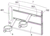
Be equipped with between holding ring 6 and the backup pad 4 and be used for adjusting its position adjustment mechanism 7, adjustment mechanism 7 is including seting up in the adjustment tank 701 of backup pad 4 inner chamber, adjustment tank 701 inner chamber transversely rotates and is connected with threaded rod 702, threaded rod 702 one end extends to the backup pad 4 outside and fixedly connected with turn-button, threaded rod 702 outside cover is equipped with regulating block 703, set up the sliding opening of inside and outside intercommunication on the lateral wall of adjustment tank 701 one end, regulating block 703 one end runs through the sliding opening and extends to the backup pad 4 front side, control threaded rod 702 rotates and cooperates between through screw thread and regulating block 703, the sliding opening restricts the position of regulating block 703 simultaneously, make regulating block 703 remove in adjustment tank 701, and then drive holding ring 6 transversely removes, the one end that regulating block 703 is located the backup pad 4 front side rotates between adjusting lever 602 and links to each other.
Be equipped with on the up end of platform body 1 and be used for cleaning the mechanism 8 that cleans its surface, clean mechanism 8 including seting up the collecting vat 801 in the platform body 1 inner chamber, set up the collection mouth 802 of inside and outside intercommunication on the collecting vat 801 up end, 1 upside of platform body transversely is provided with brush roller 803, sets up the notch of inside and outside intercommunication on the 2 lateral walls of rear side baffle, brush roller 803 one end runs through the notch and extends to outside and fixedly connected with handle.
The working principle is that the utility model moves the device to the using position when in use, the protection plate 3 and the support plate 4 are rotated to be upright, the locking block 502 is simultaneously led to enter the locking groove 501, the locking block 502 is stably fixed in the locking groove 501 through the matching action between the locking bolt and the locking hole 503, so that the protection plate 3 and the support plate 4 are stably connected together, the effective protection is provided for the operation process of the upper side of the platform body 1, then the operation tool is fixed in the fixing ring 6 through the matching action between the fixing bolt 601 and the threaded hole, the fixing ring 6 drives the operation tool to move for installation and maintenance work through the rotating action between a group of adjusting rods 602, the operation tool is more stably held by the staff, the control threaded rod 702 rotates through the matching between the threads and the adjusting block 703 in the operation process, meanwhile, the sliding opening limits the position of the adjusting block 703, so that the adjusting block 703 moves in the adjusting groove 701, and further drives the positioning ring 6 to move transversely, thereby expanding the overall moving range of the positioning ring 6.
The above, only be the concrete implementation of the preferred embodiment of the present invention, but the protection scope of the present invention is not limited thereto, and any person skilled in the art is in the technical scope of the present invention, according to the technical solution of the present invention and the utility model, the concept of which is equivalent to replace or change, should be covered within the protection scope of the present invention.