Laminating machine is feed mechanism in advance
Technical Field
The application relates to the technical field of laminating machines, in particular to a laminating machine pre-feeding mechanism.
Background
The film laminating machine can be divided into a ready-to-coat type film laminating machine and a pre-coating type film laminating machine, and is special equipment for processing the film of the printed matter. The paper and the plastic are pressed by a rubber roller and a heating roller and then are combined together to form a paper-plastic combined product.
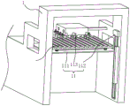
In the prior art, referring to fig. 1, an automatic feeding mechanism (11) is installed at a feeding port of a laminator main body (1), the feeding mechanism (11) comprises a supporting plate (111), a lifting assembly (112) for lifting the supporting plate (111) and a clamping assembly (113) for clamping printed matters, a worker moves a cart (4) with a plurality of printed matters placed on the supporting plate (111) of the feeding mechanism (11) of the laminator main body (1), then moves push plates (81) installed at two sides of the laminator main body (1) to align the printed matters in the vertical direction, then starts the lifting assembly (112) to lift the cart (4) on the supporting plate (111) to the feeding port of the laminator main body (1), and then the clamping assembly (113) clamps the printed matters to the feeding port of the laminator main body (1); after the clamping assembly (113) takes the printed matter on the trolley (4) away, the lifting assembly (112) is started again to lower the supporting plate (111) to the ground, and then the staff push the trolley (4) away from the supporting plate (111).
With respect to the related art among the above, the inventors consider that the following drawbacks exist: staff need manually move the shallow in feed mechanism's the backup pad, then wait that the centre gripping subassembly takes away the back with the printed matter on the shallow, again manually push away the shallow in the backup pad, increased staff's work load, the inefficiency of laminating machine material loading.
SUMMERY OF THE UTILITY MODEL
In order to improve the material loading efficiency of laminating machine, this application provides a laminating machine feed mechanism in advance.
The application provides a laminating machine feed mechanism in advance adopts following technical scheme:
the utility model provides a laminating machine is feed mechanism in advance, includes laminating machine main part, frame, first transmission subassembly and shallow, the fixed one end that sets up at the feed mechanism of laminating machine main part of frame, first transmission subassembly is including setting up first drive roll wheel, first driven roll wheel and the first driving source in the frame, first drive roll wheel and first driven roll wheel rotate the both ends that set up in the frame respectively, first driving source is used for ordering about first drive roll wheel just reversing, first transmission belt is connected on first drive roll wheel and first driven roll wheel, the wheel of shallow can contact with the roof of first transmission band, be provided with the second transmission subassembly of being connected with first transmission subassembly in the laminating machine main part.
By adopting the technical scheme, when the printed matter is moved to the feeding mechanism of the laminating machine main body, a worker firstly places the printed matter on the trolley, then the first driving source is started, the first driving roller is driven by the first driving source to rotate forwards, the trolley on the first conveying belt is driven to move to one side close to the laminating machine main body, and the trolley is moved to the second conveying assembly of the laminating machine main body; after the printed matter on the trolley is taken away by the laminating machine, the trolley is moved to the first transmission assembly by the second transmission assembly, the first driving source drives the first driving roller to rotate reversely, the trolley is driven to move to one side away from the laminating machine main body, the printed matter is placed on the trolley by a worker, the working process of manually moving the trolley by the worker is omitted, and the feeding efficiency of the laminating machine is improved.
Optionally, guide grooves are formed in the wheels of the cart along the circumferential direction of the wheels of the cart, guide strips are fixedly arranged on the top wall of the first transmission belt, two guide strips are arranged at intervals along the width direction of the first transmission belt, and the guide grooves of the wheels of the cart are connected with the guide strips in a clamped mode.
Through adopting above-mentioned technical scheme, when first conveyer belt drives the shallow and is close to or keep away from laminating machine main part direction and remove, because the guide bar with the guide way joint of the wheel of shallow, make the shallow can only remove along the length direction of first conveyer belt, prevent effectively that the shallow from taking place to deviate from at first conveyer belt removal in-process, strengthened the stability of shallow on first conveyer belt.
Optionally, the top wall of the guide strip is provided with a limiting strip for blocking the cart from moving at intervals along the length direction of the limiting strip.
By adopting the technical scheme, when the first conveying belt drives the trolley to move in the direction close to the laminating machine main body, the rear wheel of the trolley is abutted against the limiting strip, so that the trolley can be effectively prevented from moving in the direction far away from the laminating machine main body; when the first conveying belt drives the cart to move away from the direction of the film laminating machine main body, the front wheels of the cart are abutted with the limiting strips, the cart can be effectively prevented from moving towards the direction close to the film laminating machine main body, and the stability of the cart on the first conveying belt is enhanced.
Optionally, one side that the laminating machine main part was kept away from to the frame is provided with the ramp plate, the upper edge of the domatic top edge of ramp plate flushes with the top edge of first transmission band.
Through adopting above-mentioned technical scheme, when the staff need remove the shallow and go other places and get the printed matter, can remove the shallow from the ramp plate to ground with the shallow that is located on first transmission belt through the ramp plate, it is convenient to remove the shallow.
Optionally, the slope surface of the slope plate is fixedly provided with a guide block along the moving direction of the cart, and the extension line of the guide block is intersected with the extension line of the guide strip of the transmission belt.
By adopting the technical scheme, when a worker moves the cart onto the first conveying belt from the slope plate, the worker firstly clamps the guide groove on the wheel of the cart with the guide block on the slope plate, and because the extension line of the guide block is intersected with the extension line of the guide strip of the conveying belt, when the worker continuously moves the cart towards the direction of the first conveying belt and separates the guide groove on the wheel of the cart from the guide block of the slope plate, the guide groove on the wheel of the cart is clamped with the guide strip on the first conveying belt, so that the worker can conveniently position the wheel on the cart and the guide strip on the first conveying belt.
Optionally, the frame is provided with the alignment subassembly near the one end of laminating machine main part, the alignment subassembly includes two push pedals that set up along vertical direction, two the push pedal sets up the both sides in the frame along the length direction symmetry of perpendicular to frame, the push pedal is along the length direction and the frame sliding connection of perpendicular to frame, be provided with in the frame and be used for ordering about the drive arrangement that two push pedals are close to each other or keep away from.
Through adopting above-mentioned technical scheme, when first conveyer belt removed the shallow to the one side that is close to the laminating machine main part, first driving source shut down, made first conveyer belt stop to remove, then start drive arrangement and remove two push pedals to the direction that is close to each other, made the push pedal and the presswork butt on the shallow to the printing matter that will pile up on shallow is located same vertical line at the edge of frame both sides, makes things convenient for the material loading of laminating machine.
Optionally, the driving device includes two cylinders, the two cylinders are fixedly disposed at two sides of the frame, and piston rods of the two cylinders are fixedly connected to one ends of the two push plates, which are far away from each other.
Through adopting above-mentioned technical scheme, when lining up the printed matter, start the cylinder, the piston rod of cylinder drives and moves to the direction that is close to the printed matter with piston rod fixed connection's push pedal, makes push pedal and printed matter contact, and it is convenient to remove the push pedal.
Optionally, a baffle is fixedly arranged at one end of each of the two push plates close to the laminating machine main body.
Through adopting above-mentioned technical scheme, when the printed matter contact on push pedal and the shallow, the baffle will pile up a side edge that the printed matter on the shallow is close to the laminating machine main part on same perpendicular line, makes things convenient for the material loading of laminating machine.
In summary, the present application includes at least one of the following beneficial technical effects:
1. when the printed matter is moved to the feeding mechanism of the laminating machine main body, a worker starts the first driving source, the first driving source drives the first driving roller to rotate forwards, the trolley is moved to the second transmission assembly of the laminating machine main body, the worker only needs to place the printed matter on the trolley, the working process that the worker manually moves the trolley is omitted, and the feeding efficiency of the laminating machine is improved;
2. when the worker needs to move the cart to other places to take printed matters, the cart positioned on the first conveying belt can be moved to the ground from the slope plate through the slope plate, and the cart is convenient to move;
3. when the first conveying belt moves the trolley to one side close to the main body of the laminating machine, the first driving source is stopped, the first conveying belt stops moving, then the driving device is started to move the two push plates to the direction close to each other, the push plates are abutted to the printed matters on the trolley, and therefore the edges of the two sides of the rack of the printing grades stacked on the trolley are located on the same vertical line, and the laminating machine is convenient to feed.
Drawings
FIG. 1 is a schematic view of the overall structure of a feeding mechanism of a laminating machine in the prior art
Fig. 2 is a schematic view of the overall structure of a laminator pre-feeding mechanism and a laminator body according to an embodiment of the present application.
Fig. 3 is a schematic overall structure diagram of a feeding mechanism of a laminator according to an embodiment of the present application.
Fig. 4 is a partial cross-sectional view of a pre-feed mechanism of an embodiment of the present application.
Fig. 5 is a partially enlarged schematic view of a portion a in fig. 2.
Description of reference numerals: 1. a film laminating machine main body; 11. a feeding mechanism; 111. a support frame; 112. a lifting assembly; 113. a clamping assembly; 12. a second transmission assembly; 2. a frame; 3. a first transmission assembly; 31. a first conveyor belt; 32. a first driving roller; 33. a first driven roller; 34. a first drive source; 4. pushing a cart; 41. a wheel; 42. a guide groove; 5. a guide strip; 6. a limiting strip; 7. a ramp plate; 71. a slope surface; 72. a guide block; 8. an alignment assembly; 81. pushing the plate; 82. a baffle plate; 9. a drive device; 91. a cylinder; 92. a guide rod.
Detailed Description
The present application is described in further detail below with reference to figures 2-5.
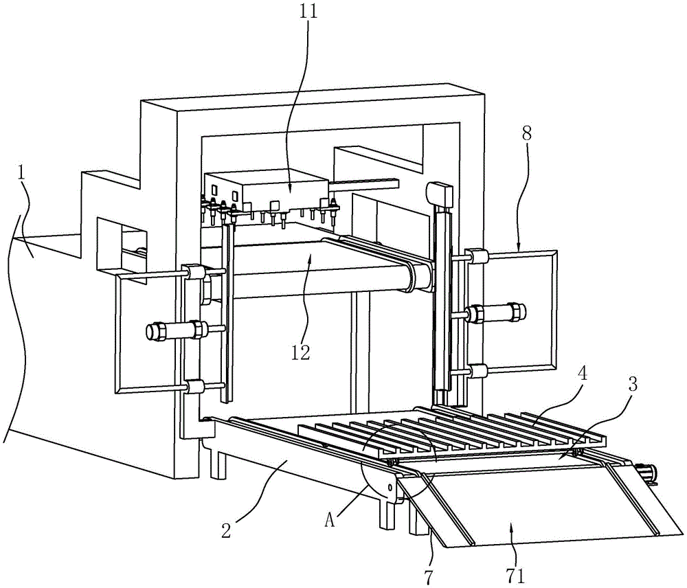
The embodiment of the application discloses laminating machine feed mechanism in advance. Referring to fig. 2, the laminator pre-feed mechanism includes a laminator body 1, a frame 2, a first transport assembly 3, and a cart 4. Laminating machine main part 1 includes feed mechanism 11, and the frame 2 welds the one end at feed mechanism 11 of laminating machine main part 1, and first transmission assembly 3 is established in frame 2. The feeding mechanism 11 is provided with a second transmission component 12, the second transmission component 12 can be connected with the first transmission component 3, and the cart 4 is slidably connected on the first transmission component 3 and the second transmission component 12.
Referring to fig. 2 and 3, the feeding mechanism 11 includes a supporting frame 111, a lifting assembly 112 for driving the supporting frame 111 to lift in a vertical direction, and a clamping assembly 113 for clamping the printed product on the cart, in this embodiment, the lifting assembly 112 is lifted by a chain, and the clamping assembly 113 is used for clamping the printed product by a suction cup. The second transmission assembly 12 is disposed on the support frame 111. In this embodiment, the second transmission assembly 12 includes a second transmission belt, a second driving roller, a second driven roller and a second driving source, the second driving roller and the second driven roller are respectively rotatably installed at two ends of the supporting frame 111, and the second transmission belt is installed on the second driving roller and the second driven roller. The second driving source adopts a servo motor, and an output shaft of the servo motor is coaxially and fixedly connected with the second driving roller. The top wall of the second conveying belt is integrally formed with an orientation strip.
Referring to fig. 3, the first conveying assembly 3 includes a first conveying belt 31, a first driving roller 32, a first driven roller 33 and a first driving source 34 which are disposed on the frame 2, the first driving roller 32 and the first driven roller 33 are respectively rotatably installed at both ends of the frame 2, and the first conveying belt 31 is connected to the first driving roller 32 and the first driven roller 33. The first driving source 34 is configured to drive the first driving roller 32 to rotate forward and backward, in this embodiment, the first driving source 34 employs a servo motor, and an output shaft of the servo motor is coaxially and fixedly connected to the first driving roller 32.
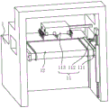
Referring to fig. 2 and 4, an aligning assembly 8 is arranged at one end of the frame 2 close to the laminator body 1, the aligning assembly 8 includes two push plates 81 installed along the vertical direction, the two push plates 81 are symmetrically installed at two sides of the frame 2 along the length direction perpendicular to the frame 2, and the push plates 81 are slidably connected with the frame 2 along the length direction perpendicular to the frame 2. A baffle plate 82 is integrally formed at one end of each push plate 81 close to the laminating machine body 1, so that the baffle plate 82 and the push plates 81 form an L shape. The frame 2 is provided with a driving device 9 for driving the two push plates 81 to approach or separate from each other. The driving device 9 comprises two cylinders 91, the two cylinders 91 are welded on two sides of the frame 2, and piston rods of the two cylinders 91 are fixedly connected with one ends of the two push plates 81, which are far away from each other. In order to improve the stability of the push plate 81 during the movement, the driving device 9 further includes four guide rods 92, one guide rod 92 is respectively installed on each side of the cylinder 91 along the vertical direction, and the two guide rods 92 on the same side are connected by a connecting rod. One end of the guide rod 92 is welded with the push plate 81, the other end is welded with the connecting rod, and the guide rod 92 is connected to the frame 2 in a sliding manner. When the first conveying belt 31 moves the cart 4 to one side close to the main body 1 of the film laminating machine, the first driving source 34 is stopped to stop the first conveying belt 31, then the cylinder 91 is started, the piston rod of the cylinder 91 drives the push plate 81 fixedly connected with the piston rod to move towards the direction close to the printed matter, so that the push plate 81 and the baffle plate 82 are both contacted with the printed matter, and therefore the edges of the two sides of the frame 2 and one edge close to the main body 1 of the film laminating machine, stacked on the cart 4, are respectively located on the same vertical line, and loading of the film laminating machine is facilitated.
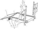
Referring to fig. 5, two sets of wheels 41 are installed at intervals in a direction perpendicular to the length direction of the first conveyor belt 31 at the bottom of the cart 4, and at least two wheels 41 are installed on each set of wheels 41 in the length direction of the first conveyor belt 31. The wheel 41 of the cart 4 is provided with a guide groove 42 along the circumferential direction of the wheel 41 of the cart 4, the top wall of the first conveying belt 31 is provided with a guide strip 5 integrally formed with the first conveying belt 31, and the extension line of the guide strip 5 is superposed with the extension line of the guide strip. Two guide strips 5 are arranged at intervals along the width direction of the first conveying belt 31, and the guide grooves 42 of the two groups of wheels 41 of the cart 4 can be respectively clamped with the two guide strips 5 on the first conveying belt 31. When the first conveying belt 31 drives the cart 4 to move close to or far away from the laminating machine main body 1, the cart 4 can only move along the length direction of the first conveying belt 31 due to the fact that the guide strips 5 are clamped with the guide grooves 42 of the wheels 41 of the cart 4, deviation of the cart 4 in the moving process of the first conveying belt 31 is effectively prevented, and stability of the cart 4 on the first conveying belt 31 is enhanced.
Referring to fig. 5, in order to improve the stability of the cart 4 on the first conveying belt 31, the top wall of the guide strip 5 is provided with the limiting strips 6 at intervals along the length direction of the limiting strips 6 for preventing the cart 4 from moving, and the limiting strips 6 are integrally formed with the guide strip 5. When the first conveying belt 31 drives the cart 4 to move in the direction close to the film laminating machine main body 1, the rear wheel 41 of the cart 4 is abutted against the limiting strip 6, so that the cart 4 can be effectively prevented from moving in the direction far away from the film laminating machine main body 1; when the first conveying belt 31 drives the cart 4 to move away from the direction of the film laminating machine main body 1, the front wheel 41 of the cart 4 is abutted against the limiting strip 6, so that the cart 4 can be effectively prevented from moving towards the direction close to the film laminating machine main body 1, and the stability of the cart 4 on the first conveying belt 31 is enhanced.
Referring to fig. 5, a slope plate 7 is installed on one side of the frame 2 away from the main body 1 of the film laminating machine, the upper edge of the slope 71 of the slope plate 7 is flush with the upper edge of the first conveying belt 31, a guide block 72 is integrally formed on the slope 71 of the slope plate 7 along the moving direction of the cart 4, and the extension line of the guide block 72 intersects with the extension line of the guide strip 5 of the conveying belt. When the worker needs to move the cart 4 to other places to take printed matters, the cart 4 on the first conveyor belt 31 can be moved to the ground from the slope plate 7 through the slope plate 7; when a worker moves the cart 4 from the slope plate 7 to the first conveying belt 31, the worker firstly clamps the guide groove 42 on the wheel 41 of the cart 4 with the guide block 72 on the slope plate 7, and because the extension line of the guide block 72 is intersected with the extension line of the guide strip 5 of the conveying belt, after the worker continuously moves the cart 4 in the direction of the first conveying belt 31 and separates the guide groove 42 on the wheel 41 of the cart 4 from the guide block 72 of the slope plate 7, the guide groove 42 on the wheel 41 of the cart 4 can be clamped with the guide strip 5 on the first conveying belt 31, so that the worker can conveniently position the wheel 41 on the cart 4 with the guide strip 5 on the first conveying belt 31, and the cart 4 is convenient to move.
The implementation principle of a laminating machine pre-feeding mechanism in the embodiment of the application is as follows: when the printed matter is moved to the feeding mechanism 11 of the film laminating machine main body 1, the trolley 4 with the printed matter is moved to the first conveying belt 31 from the slope plate 7 by a worker, then the first driving source 34 is started, the first driving roller 32 is driven to rotate positively by the first driving source 34, and the trolley 4 on the first conveying belt 31 is driven to move to one side close to the film laminating machine main body 1; when the first conveying belt 31 moves the cart 4 to one side close to the laminator main body 1, the first driving source 34 is stopped to stop the movement of the first conveying belt 31, the alignment assembly 8 is driven, the edges of the two sides of the frame 2 and one edge close to the laminator main body 1 of the printing product stacked on the cart 4 are respectively positioned on the same vertical line, then the first driving source 34 is started to move the cart 4 to the second conveying assembly 12 of the laminator main body 1, the working process that a worker manually moves the cart 4 is omitted, and the loading efficiency of the laminator is improved.
The above embodiments are preferred embodiments of the present application, and the protection scope of the present application is not limited by the above embodiments, so: all equivalent changes made according to the structure, shape and principle of the present application shall be covered by the protection scope of the present application.