CN215100093U - Cap pressing machine capable of automatically conveying workpieces - Google Patents

Cap pressing machine capable of automatically conveying workpieces Download PDF

Info

Publication number
CN215100093U
CN215100093U CN202120902636.0U CN202120902636U CN215100093U CN 215100093 U CN215100093 U CN 215100093U CN 202120902636 U CN202120902636 U CN 202120902636U CN 215100093 U CN215100093 U CN 215100093U
Authority
CN
China
Prior art keywords
disc
fixed
machine table
cavity
plate
Prior art date
Legal status (The legal status is an assumption and is not a legal conclusion. Google has not performed a legal analysis and makes no representation as to the accuracy of the status listed.)
Expired - Fee Related
Application number
CN202120902636.0U
Other languages
Chinese (zh)
Inventor
林弈志
房延庆
Current Assignee (The listed assignees may be inaccurate. Google has not performed a legal analysis and makes no representation or warranty as to the accuracy of the list.)
Hu Yangyang
Original Assignee
Haiyan Peihong Auto Parts Co ltd
Priority date (The priority date is an assumption and is not a legal conclusion. Google has not performed a legal analysis and makes no representation as to the accuracy of the date listed.)
Filing date
Publication date
Application filed by Haiyan Peihong Auto Parts Co ltd filed Critical Haiyan Peihong Auto Parts Co ltd
Priority to CN202120902636.0U priority Critical patent/CN215100093U/en
Application granted granted Critical
Publication of CN215100093U publication Critical patent/CN215100093U/en
Expired - Fee Related legal-status Critical Current
Anticipated expiration legal-status Critical

Links

Images

Landscapes

  • Press Drives And Press Lines (AREA)

Abstract

本实用新型公开了一种能自动传输工件的压帽机,包括机台、设置于机台上的按压装置、设置于机台上的传送构件一和传送构件二,设置于传送构件一和传送构件二之间的圆盘一和圆盘二,圆盘一和圆盘二上分别开设有若干开口一和开口二,机台内开设有空腔,空腔内设置有用于同时带动圆盘一和圆盘二进行相反方向转动的旋转装置,圆盘一和圆盘二外侧分别设置有限位组件一和限位组件二,具有自动传送工件且对工件进行定位的功能。

Figure 202120902636

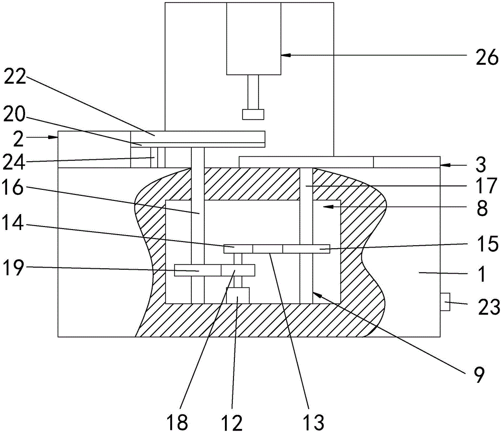
The utility model discloses a capping machine capable of automatically transporting workpieces, comprising a machine table, a pressing device arranged on the machine table, a first transmission member and a second transmission member arranged on the machine table. Disc 1 and disc 2 between the two components, disc 1 and disc 2 are respectively provided with a number of openings 1 and 2, a cavity is opened in the machine table, and a cavity is arranged in the cavity for driving the disc 1 at the same time. It is a rotating device that rotates in the opposite direction to the second disk. A limit component 1 and a limit component 2 are respectively set on the outer sides of the first disk and the second disk, which have the function of automatically transferring the workpiece and positioning the workpiece.

Figure 202120902636

Description

Cap pressing machine capable of automatically conveying workpieces
Technical Field
The utility model relates to the technical field of auto-parts, in particular to ability automatic transmission work piece press cap machine.
Background
The nut pressing machine is a machine for pressing a nut onto a specified workpiece, and at present, in the nut pressing process, the workpiece is mostly placed and positioned manually, so that the processing efficiency is low.
SUMMERY OF THE UTILITY MODEL
The utility model aims at providing a can automatic conveying work piece press cap machine has the function that automatic conveying work piece just advances line location to the work piece.
The above technical purpose of the present invention can be achieved by the following technical solutions:
the utility model provides a can automatic transmission work piece press cap machine, includes the board, sets up press device on the board, sets up conveying member one and conveying member two on the board, set up disc one and disc two between conveying member one and conveying member two, a plurality of openings one and opening two have been seted up respectively on disc one and the disc two, the cavity has been seted up in the board, be provided with in the cavity and be used for driving disc one and disc two simultaneously and carry out opposite direction pivoted rotary device, disc one and disc outside are provided with spacing subassembly one and spacing subassembly two respectively.
Adopt above-mentioned technical scheme, convey the nut in the opening one through conveying component one, convey the work piece in the opening two through conveying component two, start rotary device, rotary device drives dwang one and dwang two simultaneously and carries out the rotation of opposite direction, dwang one rotates and drives disc one and rotate, dwang two rotates and drives disc two and rotate, disc one rotates and drives the nut and rotates, spacing subassembly is spacing to the nut, prevent that the nut from shifting out opening one, disc two rotates and drives the work piece and rotate, spacing subassembly is spacing to two work pieces, prevent that the work piece from shifting out opening two, when the nut from moving the work piece upside, press the nut to the work piece through press device.
As preferred, rotary device includes motor, belt one, belt pulley one and belt pulley two, the motor is fixed in the cavity, the cavity internal rotation is provided with dwang one and dwang two, dwang one upper end is run through the cavity upper wall and is fixed with disc one, be fixed with gear one on the output shaft of motor, dwang one is fixed with gear two, gear one and the meshing of gear two, belt pulley one is fixed in on the output shaft of motor, belt pulley two is fixed in dwang two and is gone up, belt pulley one and belt pulley two pass through belt one and connect.
By adopting the technical scheme, the motor is started, the first gear and the first belt pulley are driven to rotate by the rotation of the output shaft of the motor, the second gear is driven to reversely rotate by the rotation of the first gear, the first gear drives the first rotating rod to rotate, the first rotating rod drives the first disc to rotate, the first belt pulley drives the first belt pulley to transmit, the first belt pulley drives the second belt pulley to rotate, and the second belt pulley drives the second disc to rotate, so that the effect of simultaneously driving the first disc and the second disc to rotate is achieved.
Preferably, the first limiting assembly comprises a circular bottom plate and an annular limiting plate, the upper surface of the circular bottom plate is in contact with the disc, the circular bottom plate is in rotating fit with the rotating rod, the circular bottom plate is provided with a third opening, a supporting rod is fixed on the machine table, the upper end of the supporting rod is fixed with the circular bottom plate, the annular limiting plate is sleeved on the first disc, and the annular limiting plate is fixed with the circular bottom plate.
By adopting the technical scheme, the nut is placed in the first opening, the circular base plate, the first disc and the annular limiting plate limit the nut, and the first disc rotates to drive the nut to move until the nut moves to the third opening.
Preferably, the limiting assembly comprises an arc limiting plate, the arc limiting plate is sleeved on the circular plate II in an outer sleeved mode, and the arc limiting plate is fixed with the machine table.
By adopting the technical scheme, the workpiece is placed in the second opening, and the machine table, the second disc and the arc limiting plate limit the workpiece.
Preferably, the machine table is fixed with a control button.
By adopting the technical scheme, the control button plays a role in controlling the motor.
Drawings
FIG. 1 is a schematic structural diagram of an embodiment;
FIG. 2 is a schematic diagram of the embodiment showing the positions of a first transfer member, a second transfer member, a first disc, a second disc, a first opening, a second opening, a first limit assembly, a second limit assembly, an arc-shaped limit plate and a ring-shaped limit plate;
FIG. 3 is a schematic diagram illustrating a third position of the opening on the circular bottom plate according to the embodiment.
Reference numerals: 1. a machine platform; 2. a first transmission component; 3. a second conveying component; 4. a first disc; 5. a second disc; 6. a first opening; 7. a second opening; 8. a cavity; 9. a rotating device; 10. a first limiting component; 11. a second limiting component; 12. a motor; 13. a first belt; 14. a first belt pulley; 15. a second belt pulley; 16. rotating the first rod; 17. rotating the second rod; 18. a first gear; 19. a second gear; 20. a circular base plate; 21. an arc limiting plate; 22. an annular limiting plate; 23. a control button; 24. a support bar; 25. opening three; 26. and a pressing device.
Detailed Description
The following is only the preferred embodiment of the present invention, the protection scope is not limited to this embodiment, and all technical solutions belonging to the idea of the present invention should belong to the protection scope of the present invention. It should also be noted that, for those skilled in the art, various modifications and decorations can be made without departing from the principle of the present invention, and such modifications and decorations should also be regarded as the protection scope of the present invention.
Referring to fig. 1 to 3, a cap pressing machine capable of automatically conveying workpieces comprises a machine table 1, a pressing device 26 arranged on the machine table 1, a first conveying member 2 and a second conveying member 3 arranged on the machine table 1, a first disk 4 and a second disk 5 arranged between the first conveying member 2 and the second conveying member 3, wherein a plurality of openings I6 and openings II 7 are respectively arranged on the first disk 4 and the second disk 5, nuts are conveyed into the openings I6 through the first conveying member 2, the workpieces are conveyed into the openings II 7 through the second conveying member 3, a first limiting assembly 10 and a second limiting assembly 11 are respectively arranged on the outer sides of the first disk 4 and the second disk 5, the first limiting assembly 10 comprises a circular bottom plate 20 and an annular limiting plate 22, the upper surface of the circular bottom plate 20 is in contact with the second disk 5, the circular bottom plate 20 is in rotating fit with a first rotating rod 16, a supporting rod 24 is fixed on the machine table 1, and the upper end of the supporting rod 24 is fixed with the circular bottom plate 20, the annular limiting plate 22 is sleeved on the first disc 4, the annular limiting plate 22 is fixed with the circular bottom plate 20, and the nut is limited by the circular bottom plate 20, the first disc 4 and the annular limiting plate 22.
As shown in fig. 1 and 2, the second limiting component 11 includes an arc-shaped limiting plate 21, the arc-shaped limiting plate 21 is externally sleeved on the second circular plate, the arc-shaped limiting plate 21 is fixed with the machine table 1, the second circular disc 5 and the arc-shaped limiting plate 21 limit a workpiece, a cavity 8 is formed in the machine table 1, a rotating device 9 for simultaneously driving the first circular disc 4 and the second circular disc 5 to rotate in opposite directions is arranged in the cavity 8, the rotating device 9 includes a motor 12, a first belt 13, a first belt pulley 14 and a second belt pulley 15, the motor 12 is fixed in the cavity 8, a control button 23 is fixed on the machine table 1, the motor 12 is started by pressing the control button 23, a first gear 18 is fixed on an output shaft of the motor 12, the first belt pulley 14 is fixed on an output shaft of the motor 12, the first gear 18 and the first belt pulley 14 are driven to rotate by rotation of the output shaft of the motor 12, a first rotating rod 16 and a second rotating rod 17 are rotatably arranged in the cavity 8, a second gear 19 is fixed on the first rotating rod 16, the first gear 18 is meshed with the second gear 19, the second gear 19 rotates to drive the second gear 19 to rotate reversely, the second gear 19 drives the first rotating rod 16 to rotate, the upper end of the first rotating rod 16 penetrates through the upper wall of the cavity 8 and is fixed with the first disc 4, the first rotating rod 16 rotates to drive the first disc 4 to rotate, the second belt pulley 15 is fixed on the second rotating rod 17, the first belt pulley 14 is connected with the second belt pulley 15 through a first belt 13, the first belt pulley 14 rotates to drive the first belt 13 to transmit, the first belt 13 transmits to drive the second belt pulley 15 to rotate, the second belt pulley 15 rotates to drive the second disc 5 to rotate, at the moment, the rotating directions of the first disc 4 and the second disc 5 are opposite, the first disc 4 rotates to drive the nut to rotate, the second disc 5 rotates to drive the workpiece to rotate, the circular bottom plate 20 is provided with a third opening 25, and when the nut moves to the third opening 25, the nut is positioned on the upper side of the workpiece, finally, the nut is pressed onto the workpiece by the pressing device 26.

Claims (5)

1.一种能自动传输工件的压帽机,包括机台(1)、设置于机台(1)上的按压装置(26)、设置于机台(1)上的传送构件一(2)和传送构件二(3),其特征在于,所述设置于传送构件一(2)和传送构件二(3)之间的圆盘一(4)和圆盘二(5),所述圆盘一(4)和圆盘二(5)上分别开设有若干开口一(6)和开口二(7),所述机台(1)内开设有空腔(8),所述空腔(8)内设置有用于同时带动圆盘一(4)和圆盘二(5)进行相反方向转动的旋转装置(9),所述圆盘一(4)和圆盘二(5)外侧分别设置有限位组件一(10)和限位组件二(11)。1. A capping machine capable of automatically transferring workpieces, comprising a machine table (1), a pressing device (26) arranged on the machine table (1), and a transmission member one (2) arranged on the machine table (1) and conveying member two (3), characterized in that the disc one (4) and disc two (5) disposed between the conveying member one (2) and the conveying member two (3), the disc The first (4) and the second disk (5) are respectively provided with a number of openings (6) and openings (7), the machine table (1) is provided with a cavity (8), the cavity (8) ) is provided with a rotating device (9) for simultaneously driving disc one (4) and disc two (5) to rotate in opposite directions, and the outer sides of disc one (4) and disc two (5) are respectively provided with limited Position component one (10) and limit component two (11). 2.根据权利要求1所述的一种能自动传输工件的压帽机,其特征在于,所述旋转装置(9)包括电机(12)、皮带一(13)、皮带轮一(14)和皮带轮二(15),所述电机(12)固定于空腔(8)内,所述空腔(8)内转动设置有转动杆一(16)和转动杆二(17),所述转动杆一(16)上端贯穿空腔(8)上壁与圆盘一(4)固定,所述电机(12)的输出轴上固定有齿轮一(18),所述转动杆一(16)上固定有齿轮二(19),所述齿轮一(18)与齿轮二(19)啮合,所述皮带轮一(14)固定于电机(12)的输出轴上,所述皮带轮二(15)固定于转动杆二(17)上,所述皮带轮一(14)和皮带轮二(15)通过皮带一(13)连接。2. A capping machine capable of automatically transferring workpieces according to claim 1, wherein the rotating device (9) comprises a motor (12), a belt (13), a pulley (14) and a pulley Two (15), the motor (12) is fixed in the cavity (8), and a rotating rod (16) and a rotating rod two (17) are rotatably arranged in the cavity (8). (16) The upper end penetrates the upper wall of the cavity (8) and is fixed to the disc one (4), the output shaft of the motor (12) is fixed with a gear one (18), and the rotating rod one (16) is fixed with a gear one (16). The second gear (19), the first gear (18) meshes with the second gear (19), the first pulley (14) is fixed on the output shaft of the motor (12), and the second pulley (15) is fixed on the rotating rod On the second (17), the first pulley (14) and the second pulley (15) are connected by the first belt (13). 3.根据权利要求2所述的一种能自动传输工件的压帽机,其特征在于,所述限位组件一(10)包括圆形底板(20)和环形限位板(22),所述圆形底板(20)的上表面与圆盘二(5)相接触,所述圆形底板(20)与转动杆一(16)转动配合,所述圆形底板(20)上开设有开口三(25),所述机台(1)上固定有支撑杆(24),所述支撑杆(24)上端与圆形底板(20)固定,所述环形限位板(22)外套于圆盘一(4)上,所述环形限位板(22)与圆形底板(20)固定。3. A capping machine capable of automatically transferring workpieces according to claim 2, characterized in that, the limit assembly one (10) comprises a circular base plate (20) and an annular limit plate (22), so The upper surface of the circular base plate (20) is in contact with the second disc (5), the circular base plate (20) is rotatably matched with the rotating rod one (16), and the circular base plate (20) is provided with an opening Three (25), a support rod (24) is fixed on the machine table (1), the upper end of the support rod (24) is fixed with the circular bottom plate (20), and the annular limit plate (22) is sleeved on the circular bottom plate (22). On the first plate (4), the annular limiting plate (22) is fixed to the circular bottom plate (20). 4.根据权利要求3所述的一种能自动传输工件的压帽机,其特征在于,所述限位组件二(11)包括弧形限位板(21),所述弧形限位板(21)外套于圆盘二(5)上,所述弧形限位板(21)与机台(1)固定。4. A capping machine capable of automatically transferring workpieces according to claim 3, wherein the second limiting component (11) comprises an arc-shaped limiting plate (21), and the arc-shaped limiting plate (21) The outer casing is placed on the second disc (5), and the arc-shaped limiting plate (21) is fixed to the machine table (1). 5.根据权利要求4所述的一种能自动传输工件的压帽机,其特征在于,所述机台(1)上固定有控制按钮(23)。5. A capping machine capable of automatically transferring workpieces according to claim 4, wherein a control button (23) is fixed on the machine table (1).
CN202120902636.0U 2021-04-28 2021-04-28 Cap pressing machine capable of automatically conveying workpieces Expired - Fee Related CN215100093U (en)

Priority Applications (1)

Application Number Priority Date Filing Date Title
CN202120902636.0U CN215100093U (en) 2021-04-28 2021-04-28 Cap pressing machine capable of automatically conveying workpieces

Applications Claiming Priority (1)

Application Number Priority Date Filing Date Title
CN202120902636.0U CN215100093U (en) 2021-04-28 2021-04-28 Cap pressing machine capable of automatically conveying workpieces

Publications (1)

Publication Number Publication Date
CN215100093U true CN215100093U (en) 2021-12-10

Family

ID=79289998

Family Applications (1)

Application Number Title Priority Date Filing Date
CN202120902636.0U Expired - Fee Related CN215100093U (en) 2021-04-28 2021-04-28 Cap pressing machine capable of automatically conveying workpieces

Country Status (1)

Country Link
CN (1) CN215100093U (en)

Similar Documents

Publication Publication Date Title
CN112794044B (en) Conveyer for solar energy production
CN205169743U (en) Assembly line work piece turning device
CN213504828U (en) Industrial automation's conveyor
CN215100093U (en) Cap pressing machine capable of automatically conveying workpieces
JP2003236899A (en) Injection molded product removal machine and removal system
CN112707004A (en) Body clamping and conveying device for food packaging
CN105514015B (en) Machine is thinned in a kind of rotating table device and wafer
CN214454873U (en) Workpiece reverse rotation transfer mechanism
CN211516911U (en) a processing line
CN217675600U (en) Automatic production's tilting mechanism between stewing
JP2009095940A5 (en)
CN214980116U (en) A polishing equipment for sapphire wafers
CN115258640A (en) Multi-station turnover device
CN205366983U (en) Shake formula feed machine
CN212471496U (en) A robot for handling pallets
CN221539714U (en) Industrial robot processes positioner
CN108313671B (en) Blanking equipment
CN115432411B (en) Goods turning device and double production line that variable speed and at uniform velocity combine
CN121104580A (en) An assembly machine
CN222037557U (en) A flat metal deburring and chamfering wire drawing machine
CN110744360A (en) Cookware tool and cookware auxiliary processing system
CN110976574B (en) Metal rod bending mechanical arm
CN220408097U (en) Cutter water mill processing interfacing apparatus and water mill processing equipment
CN223456349U (en) Foam molding machine
CN218260648U (en) Multi-station continuous cup discharging mechanism

Legal Events

Date Code Title Description
GR01 Patent grant
GR01 Patent grant
TR01 Transfer of patent right

Effective date of registration: 20231018

Address after: No. 07, Nangang Group, Pingtian Village, Zilaiqiao Town, Mingguang City, Chuzhou City, Anhui Province, 239400

Patentee after: Hu Yangyang

Address before: 314300 Building 2, Fenghuang community, Wanghai street, Haiyan County, Jiaxing City, Zhejiang Province (Youshang hardware)

Patentee before: Haiyan Peihong Auto Parts Co.,Ltd.

TR01 Transfer of patent right
CF01 Termination of patent right due to non-payment of annual fee

Granted publication date: 20211210

CF01 Termination of patent right due to non-payment of annual fee