CN215299529U - Wedge-shaped parallel groove clamp - Google Patents
Wedge-shaped parallel groove clamp Download PDFInfo
- Publication number
- CN215299529U CN215299529U CN202121730821.2U CN202121730821U CN215299529U CN 215299529 U CN215299529 U CN 215299529U CN 202121730821 U CN202121730821 U CN 202121730821U CN 215299529 U CN215299529 U CN 215299529U
- Authority
- CN
- China
- Prior art keywords
- wedge
- shaped
- sides
- parallel groove
- block
- Prior art date
- Legal status (The legal status is an assumption and is not a legal conclusion. Google has not performed a legal analysis and makes no representation as to the accuracy of the status listed.)
- Active
Links
- 241000121266 Donacidae Species 0.000 claims abstract description 21
- 230000000694 effects Effects 0.000 claims abstract description 5
- 230000005540 biological transmission Effects 0.000 claims description 15
- 230000000149 penetrating effect Effects 0.000 claims 1
- 230000009286 beneficial effect Effects 0.000 abstract description 2
- XAGFODPZIPBFFR-UHFFFAOYSA-N aluminium Chemical compound [Al] XAGFODPZIPBFFR-UHFFFAOYSA-N 0.000 description 2
- 229910052782 aluminium Inorganic materials 0.000 description 2
- 238000000034 method Methods 0.000 description 2
- 230000004075 alteration Effects 0.000 description 1
- 239000004020 conductor Substances 0.000 description 1
- 230000002349 favourable effect Effects 0.000 description 1
- 238000012986 modification Methods 0.000 description 1
- 230000004048 modification Effects 0.000 description 1
- 238000006467 substitution reaction Methods 0.000 description 1
Images


Landscapes
- Gripping Jigs, Holding Jigs, And Positioning Jigs (AREA)
Abstract
The utility model discloses a wedge parallel groove clamp, including C type wedge shell and voussoir, the voussoir sets up in the inside of C type wedge shell through an adjusting part activity, and a adjusting part includes spout, slider and first handle screw rod, and the middle part in C type wedge shell inner wall bottom is seted up to the spout, and the fixed middle part that sets up in the voussoir bottom of slider, slider slip set up in the inside of spout, and first handle screw rod rotates and alternates the inside that sets up at the spout, the beneficial effects of the utility model are that: the first handle screw rod through rotating first adjusting part can drive the slider and slide in the inside of spout, can drive the voussoir and make a round trip to slide then, and two arc thread clamps on the rethread voussoir cooperate with two wire casings and carry out the centre gripping, and position and the C type wedge shell through adjusting the voussoir cooperate can carry out the centre gripping to the wire of unidimensional in the certain limit, make wedge parallel groove clamp can adjust the centre gripping as required, and is more practical.
Description
Technical Field
The utility model relates to a parallel groove clamp, in particular to wedge parallel groove clamp belongs to electric power fitting technical field.
Background
The parallel groove clamp is a contact fitting for parallelly connecting wires to transmit electrical load, has wide application range, and can be applied to jumper connection of non-linear towers, T connection, branch line and the like at non-bearing connection positions of an electric power system, down lead connection of electrical equipment such as switches, transformers and the like, ground down lead connection of lightning conductors and the like. The wedge-shaped wire clamp is suitable for non-bearing connection or branching between overhead insulated aluminum stranded wires or steel-cored aluminum stranded wires in an overhead distribution line, and the insulating cover and the wire clamp are matched for use and play an insulating and protecting role.
The existing wedge-shaped parallel groove clamp is simple in structure, cannot be adjusted to be used as required, particularly cannot be adjusted to be clamped according to the sizes of different wires, is poor in practicability, inconvenient to disassemble and assemble, and wastes time and energy in the disassembling and assembling process.
SUMMERY OF THE UTILITY MODEL
An object of the utility model is to provide a wedge parallel groove clamp to current wedge parallel groove clamp that proposes in solving above-mentioned background art can't adjust the centre gripping according to the size of different wires, and the practicality is poor and the inconvenient problem of dismouting.
In order to achieve the above object, the utility model provides a following technical scheme: the utility model provides a wedge parallel groove clamp, includes C type wedge shell and voussoir, the voussoir sets up the inside at C type wedge shell through first adjusting part activity, first adjusting part includes spout, slider and first handle screw rod, the middle part at C type wedge shell inner wall bottom is seted up to the spout, the fixed middle part that sets up in the voussoir bottom of slider, the slider slides and sets up the inside at the spout, first handle screw rod rotates and alternates the inside that sets up at the spout, just the middle part of first handle screw rod alternates with the middle part screw thread of slider and be connected, the wire casing has all been seted up to the both sides of C type wedge shell inner wall, the both sides of voussoir all are equipped with arc splint, the inner chamber has been seted up to the inside of voussoir, the inside of inner chamber be equipped with two arc splint matched with second adjusting part.
As a preferred technical scheme of the utility model, the second adjusting part includes four drive blocks and wedge seat, four the drive block is fixed respectively and is set up in the inboard of two arc thread clamps, and four the drive block slides respectively and alternates the setting in the both sides of voussoir, the wedge seat activity sets up in the inside of inner chamber, just the wedge seat cooperatees with four drive blocks, the inside both sides of inner chamber are rotated respectively and alternate and are installed two second handle screw rods, two the middle part of second handle screw rod alternates with the both sides screw thread at wedge seat middle part respectively and is connected.
As an optimal technical scheme of the utility model, four the inclined plane that the angle is the same is all seted up to the inboard top of driving block and the bottom of wedge seat both sides.
As a preferred technical scheme of the utility model, the second adjusting part still includes four fixed plates and four gag lever posts, four the fixed plate is fixed the bottom that sets up at four driving blocks respectively, four the gag lever post is fixed the bottom that sets up in inner chamber inner wall both sides respectively, four the middle part that runs through four fixed plates is slided respectively to the one end of gag lever post.
As a preferred technical scheme of the utility model, four all the cover is equipped with the spring on the gag lever post, four the one end of spring respectively with the outside fixed connection of four fixed plates, four the other end of spring respectively with the bottom fixed connection of inner chamber inner wall both sides.
As an optimal technical scheme of the utility model, four the one end of gag lever post is all fixed and is equipped with the anticreep dish.
As an optimal technical scheme of the utility model, two the position and the size of arc thread tension board are corresponding with the position and the size of two wire casing respectively.
Compared with the prior art, the beneficial effects of the utility model are that: the utility model relates to a wedge parallel groove clamp, first handle screw rod through rotating first adjusting part can drive the slider and slide in the inside of spout, can drive the voussoir and make a round trip to slide then, two arc clamps on the rethread voussoir cooperate with two wire casings and carry out the centre gripping, position and the C type wedge shell through adjusting the voussoir cooperate can carry out the centre gripping to not unidimensional wire in the certain limit, make wedge parallel groove clamp can adjust the centre gripping as required, it is more practical, be convenient for the whole wedge parallel groove clamp of dismouting simultaneously, dismouting labour saving and time saving, and can drive four transmission blocks of wedge seat transmission through two second handle screw rods that rotate second adjusting part and drive two arc clamps and adjust, further enlarge wedge parallel groove clamp's application scope.
Drawings
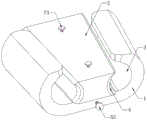
Fig. 1 is a schematic view of the overall structure of the present invention;
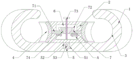
fig. 2 is a schematic sectional structure of the present invention;
fig. 3 is an enlarged schematic view of a portion a of fig. 2 according to the present invention;
fig. 4 is a schematic top view of the cross-sectional structure of the present invention.
In the figure: 1. a C-shaped wedge shell; 2. a wedge block; 3. a wire slot; 4. an arc-shaped wire clamping plate; 5. a first adjustment assembly; 51. a chute; 52. a slider; 53. a first handle screw; 6. an inner cavity; 7. a second adjustment assembly; 71. a transmission block; 72. a wedge seat; 73. a second handle screw; 74. a bevel; 75. a fixing plate; 76. a limiting rod; 77. a spring; 78. the anticreep dish.
Detailed Description
The technical solutions in the embodiments of the present invention will be described clearly and completely with reference to the accompanying drawings in the embodiments of the present invention, and it is obvious that the described embodiments are only some embodiments of the present invention, not all embodiments. Based on the embodiments in the present invention, all other embodiments obtained by a person skilled in the art without creative work belong to the protection scope of the present invention.
Please refer to fig. 1-4, the utility model provides a wedge parallel groove clamp, including C type wedge shell 1 and voussoir 2, voussoir 2 sets up the inside at C type wedge shell 1 through the activity of first adjusting part 5, first adjusting part 5 includes spout 51, slider 52 and first handle screw 53, spout 51 is seted up at the middle part of C type wedge shell 1 inner wall bottom, the fixed middle part that sets up in 2 bottoms of voussoir of slider 52, slider 52 slides and sets up the inside at spout 51, first handle screw 53 rotates and alternates the inside that sets up at spout 51, and the middle part of first handle screw 53 alternates with the middle part screw thread of slider 52 and be connected, wire casing 3 has all been seted up to the both sides of C type wedge shell 1 inner wall, the both sides of voussoir 2 all are equipped with arc clamp 4, cooperate with two wire casings 3 through two arc clamp 4 on voussoir 2 and carry out the centre gripping, can cooperate with C type wedge shell 1 to different sizes in a certain extent through the position that first adjusting part 5 adjusted voussoir 2 and cooperate The wire carry out the centre gripping, make wedge parallel groove clamp can adjust the centre gripping as required, and more practical, inner chamber 6 has been seted up to the inside of voussoir 2, and the inside of inner chamber 6 is equipped with two arc clamp 4 matched with second adjusting part 7.
Preferably, the second adjusting assembly 7 comprises four transmission blocks 71 and a wedge seat 72, the four transmission blocks 71 are respectively fixedly arranged at the inner sides of the two arc-shaped clamping plates 4, the four transmission blocks 71 are respectively slidably and penetratingly arranged at two sides of the wedge block 2, the wedge seat 72 is movably arranged inside the inner cavity 6, the wedge seat 72 is matched with the four transmission blocks 71, two second handle screws 73 are respectively rotatably and penetratingly arranged at two sides inside the inner cavity 6, the middle parts of the two second handle screws 73 are respectively and penetratingly connected with two threads at the middle part of the wedge seat 72, the wedge seat 72 can be driven by rotating the two second handle screws 73 to drive the four transmission blocks 71 to drive the two arc-shaped clamping plates 4 to adjust, and the wedge-shaped parallel groove clamp is suitable for clamping of wires with different sizes in a certain range; inclined planes 74 with the same angle are formed at the tops of the inner sides of the four transmission blocks 71 and the bottoms of the two sides of the wedge-shaped seat 72, and the inclined planes 74 are formed, so that the wedge-shaped seat 72 can be favorable for driving the four transmission blocks 71 to drive the two arc-shaped wire clamps 4 to be adjusted; the second adjusting assembly 7 further comprises four fixing plates 75 and four limiting rods 76, the four fixing plates 75 are respectively fixedly arranged at the bottom ends of the four transmission blocks 71, the four limiting rods 76 are respectively fixedly arranged at the bottoms of the two sides of the inner wall of the inner cavity 6, one ends of the four limiting rods 76 respectively penetrate through the middles of the four fixing plates 75 in a sliding manner, and the four transmission blocks 71 can be limited in movement by matching the limiting rods 76 with the fixing plates 75; the four limiting rods 76 are all sleeved with springs 77, one ends of the four springs 77 are respectively fixedly connected with the outer sides of the four fixing plates 75, the other ends of the four springs 77 are respectively fixedly connected with the bottoms of the two sides of the inner wall of the inner cavity 6, the automatic reset purpose can be achieved through the elastic action of the springs 77, and the four transmission blocks 71 can drive the two arc-shaped clamping plates 4 to automatically reset; anti-falling discs 78 are fixedly arranged at one ends of the four limiting rods 76, and the limiting rods 76 can be prevented from falling off from the fixing plate 75 through the anti-falling discs 78; the positions and the sizes of the two arc-shaped wire clamps 4 correspond to the positions and the sizes of the two wire slots 3 respectively, so that the two arc-shaped wire clamps 4 can be matched with the two wire slots 3 to clamp wires.
When the wedge-shaped parallel groove clamp is used, firstly, the first handle screw 53 is rotated to drive the slide block 52 to drive the slide side of the wedge block 2, at the moment, the wedge block 2 and the C-shaped wedge shell 1 are staggered to facilitate clamping of wires, after the clamping is carried out to the inner parts of the two wire grooves 3, the first handle screw 53 is rotated to drive the slide block 52 to drive the wedge block 2 to slide until the two arc-shaped clamp plates 4 are respectively matched with the two wire grooves 3 to clamp the wires, the two arc-shaped clamp plates 4 on the wedge block 2 are matched with the two wire grooves 3 to clamp, the wires with different sizes can be clamped within a certain range by adjusting the position of the wedge block 2 to be matched with the C-shaped wedge shell 1, so that the wedge-shaped parallel groove clamp can adjust and clamp as required, is more practical, is convenient to disassemble and assemble the whole wedge-shaped parallel groove clamp, the disassembly and assembly are time-saving and labor-saving, and in the clamping process, the two second handle screws 73 can be rotated to drive the wedge seat 72 to move up and down, wedge seat 72 moves down can drive four driving blocks 71 and outwards expand and drive two arc-shaped clamps 4 and adjust, further enlarges the application scope of wedge parallel groove clamp, and the elastic action through spring 77 can reach automatic re-setting's purpose when wedge seat 72 moves up, ensures that four driving blocks 71 can drive two arc-shaped clamps 4 automatic re-setting.
Although embodiments of the present invention have been shown and described, it will be appreciated by those skilled in the art that changes, modifications, substitutions and alterations can be made in these embodiments without departing from the principles and spirit of the invention, the scope of which is defined in the appended claims and their equivalents.
Claims (7)
1. A wedge-shaped parallel groove clamp comprises a C-shaped wedge shell (1) and a wedge block (2), and is characterized in that the wedge block (2) is movably arranged in the C-shaped wedge shell (1) through a first adjusting component (5), the first adjusting component (5) comprises a sliding groove (51), a sliding block (52) and a first handle screw rod (53), the sliding groove (51) is formed in the middle of the bottom end of the inner wall of the C-shaped wedge shell (1), the sliding block (52) is fixedly arranged in the middle of the bottom end of the wedge block (2), the sliding block (52) is slidably arranged in the sliding groove (51), the first handle screw rod (53) is rotatably and alternately arranged in the sliding groove (51), the middle of the first handle screw rod (53) is in threaded penetrating connection with the middle of the sliding block (52), wire grooves (3) are formed in two sides of the inner wall of the C-shaped wedge shell (1), arc-shaped wire clamps (4) are arranged on two sides of the wedge block (2), an inner cavity (6) is formed in the wedge block (2), and a second adjusting component (7) matched with the two arc-shaped clamping plates (4) is arranged in the inner cavity (6).
2. A wedge-shaped parallel groove clamp according to claim 1, wherein: second adjusting part (7) include four driving block (71) and wedge seat (72), four driving block (71) is fixed respectively and is set up the inboard at two arc-shaped thread clamps (4), and four driving block (71) slides respectively and alternates and set up the both sides at voussoir (2), wedge seat (72) activity sets up in the inside of inner chamber (6), just wedge seat (72) cooperate with four driving block (71), two second handle screw rods (73) are installed to the inside both sides of inner chamber (6) rotation respectively and alternate, two the middle part of second handle screw rod (73) alternates with the both sides screw thread at wedge seat (72) middle part respectively and is connected.
3. A wedge-shaped parallel groove clamp according to claim 2, wherein: inclined planes (74) with the same angle are arranged at the tops of the inner sides of the four transmission blocks (71) and the bottoms of the two sides of the wedge-shaped seat (72).
4. A wedge-shaped parallel groove clamp according to claim 2, wherein: the second adjusting component (7) further comprises four fixing plates (75) and four limiting rods (76), the four fixing plates (75) are respectively fixedly arranged at the bottom ends of the four transmission blocks (71), the four limiting rods (76) are respectively fixedly arranged at the bottoms of two sides of the inner wall of the inner cavity (6), and one ends of the four limiting rods (76) respectively penetrate through the middle portions of the four fixing plates (75) in a sliding mode.
5. A wedge-shaped parallel groove clamp according to claim 4, wherein: four all the cover is equipped with spring (77), four on gag lever post (76) the one end of spring (77) respectively with the outside fixed connection of four fixed plates (75), four the other end of spring (77) respectively with the bottom fixed connection of inner chamber (6) inner wall both sides.
6. A wedge-shaped parallel groove clamp according to claim 4, wherein: and one end of each of the four limiting rods (76) is fixedly provided with an anti-falling disc (78).
7. A wedge-shaped parallel groove clamp according to claim 1, wherein: the positions and the sizes of the two arc-shaped clamping plates (4) correspond to those of the two wire grooves (3) respectively.
Priority Applications (1)
| Application Number | Priority Date | Filing Date | Title |
|---|---|---|---|
| CN202121730821.2U CN215299529U (en) | 2021-07-28 | 2021-07-28 | Wedge-shaped parallel groove clamp |
Applications Claiming Priority (1)
| Application Number | Priority Date | Filing Date | Title |
|---|---|---|---|
| CN202121730821.2U CN215299529U (en) | 2021-07-28 | 2021-07-28 | Wedge-shaped parallel groove clamp |
Publications (1)
| Publication Number | Publication Date |
|---|---|
| CN215299529U true CN215299529U (en) | 2021-12-24 |
Family
ID=79525046
Family Applications (1)
| Application Number | Title | Priority Date | Filing Date |
|---|---|---|---|
| CN202121730821.2U Active CN215299529U (en) | 2021-07-28 | 2021-07-28 | Wedge-shaped parallel groove clamp |
Country Status (1)
| Country | Link |
|---|---|
| CN (1) | CN215299529U (en) |
Cited By (1)
| Publication number | Priority date | Publication date | Assignee | Title |
|---|---|---|---|---|
| US20240097415A1 (en) * | 2022-09-19 | 2024-03-21 | EcoFasten Solar, LLC | Wire Clamp |
-
2021
- 2021-07-28 CN CN202121730821.2U patent/CN215299529U/en active Active
Cited By (3)
| Publication number | Priority date | Publication date | Assignee | Title |
|---|---|---|---|---|
| US20240097415A1 (en) * | 2022-09-19 | 2024-03-21 | EcoFasten Solar, LLC | Wire Clamp |
| US11949217B1 (en) * | 2022-09-19 | 2024-04-02 | EcoFasten Solar, LLC | Wire clamp |
| US12300985B2 (en) | 2022-09-19 | 2025-05-13 | EcoFasten Solar, LLC | Wire clamp |
Similar Documents
| Publication | Publication Date | Title |
|---|---|---|
| CN105226412B (en) | Multifunctional grounding wire insulating bar | |
| CN211965749U (en) | Cable cutting device with both ends fixed knot constructs | |
| CN210608317U (en) | Wire stripping mechanism for overhead insulated wire | |
| CN213072070U (en) | Electric power fitting with insulation protection device | |
| CN215299529U (en) | Wedge-shaped parallel groove clamp | |
| CN210296760U (en) | Anti-drop device of power cable connector | |
| CN209461659U (en) | It can livewire work lightning-protection piercing grounding wire clip | |
| CN220585667U (en) | New energy battery flexible soft copper bar connector | |
| CN216215740U (en) | Plug-in type air insulation bus duct structure | |
| CN214069486U (en) | Insulated bus frame convenient to adjust inside centre gripping bore | |
| CN218415581U (en) | First device is shelled to cable | |
| CN213817171U (en) | A power fitting applied to overhead lines | |
| CN212210424U (en) | Strain clamp convenient to lock and used for strain insulator-string set | |
| CN116913626A (en) | Anti-loosening suspension insulator | |
| CN116247453A (en) | Special binding clip of arrester with adjustable | |
| CN219959954U (en) | A kind of power cable stripping device | |
| CN210628938U (en) | Lightning protection device for operation and maintenance of power transmission line | |
| CN216923903U (en) | Fault monitoring device of power communication equipment | |
| CN210517327U (en) | Lightning protection device for distribution transformer | |
| CN223093452U (en) | Bus duct connection structure | |
| CN214588704U (en) | Arc striking piece structure of frame arc extinguish chamber | |
| CN222826737U (en) | Edge-closed laminated busbar | |
| CN216413737U (en) | Dual-purpose insulating wire locking rod device for live working of distribution line | |
| CN222016170U (en) | Electric power connecting fitting | |
| CN220325246U (en) | Overhead cable fixing device |
Legal Events
| Date | Code | Title | Description |
|---|---|---|---|
| GR01 | Patent grant | ||
| GR01 | Patent grant |