Building curtain wall with wind resistance function
Technical Field
The utility model relates to the field of building curtain walls, in particular to a building curtain wall with a wind resistance function.
Background
Building curtain walls refer to the non-load bearing outer wall envelope of a building, usually consisting of panels (glass, metal, slate, ceramic, etc.) and a supporting structure behind (aluminum beam columns, steel structures, glass ribs, etc.).
But current building curtain shock-absorbing capacity is poor, leads to not having the anti-wind function to make building curtain take place the damage phenomenon easily when receiving the strong wind and assault, and then reduced life, so current building curtain can't satisfy people's user demand, and the work of giving people brings inconvenience.
Therefore, the building curtain wall with the wind resisting function is provided for solving the problems.
SUMMERY OF THE UTILITY MODEL
In order to make up for the defects of the prior art and solve the problem that the building curtain wall does not have the wind resistance function, the utility model provides a building curtain wall with the wind resistance function.
The technical scheme adopted by the utility model for solving the technical problems is as follows: the utility model relates to a building curtain wall with a wind resistance function, which comprises a curtain wall body; the curtain wall comprises a curtain wall body and is characterized in that a supporting rod is fixedly connected to one side of the curtain wall body, a connecting block is fixedly connected to the outer wall of the supporting rod, a movable rod is movably connected to the inside of the connecting block, scroll damping springs are fixedly connected to the inner walls of the two ends of the movable rod, a first connecting shaft and a second connecting shaft are fixedly connected to the inner walls of the scroll damping springs respectively, and movable blocks are fixedly connected to the two ends of the second connecting shaft.
The utility model discloses a damping device for the automobile seat, including movable block, bracing piece, mounting panel, first damping spring, the inside swing joint of one end of movable block has the dead lever, the both ends fixedly connected with mounting panel of dead lever, the outer wall swing joint of dead lever has first damping spring, the inner wall fixedly connected with supporting shoe of one side of mounting panel, the inner wall fixedly connected with second damping spring of supporting shoe, the bracing piece stretches into the inside one end fixedly connected with stopper of supporting shoe.
Preferably, the connecting blocks are symmetrically distributed on the outer wall of the supporting rod, and the inner wall of the connecting block is fixedly connected with the two ends of the first connecting shaft.
Preferably, the side, close to each other, of the connecting block and the movable block is viewed as a concave structure in plan, and the width of the groove of the connecting block and the width of the groove of the movable block are larger than the width of the movable rod.
Preferably, the two ends of the movable rod respectively form a rotating structure with the first connecting shaft and the second connecting shaft through a scroll damping spring, and the movable rod is arranged obliquely in front view.
Preferably, one side of the movable block is fixedly connected with one end of the first damping spring, and the movable block and the fixed rod form a telescopic structure through the first damping spring.
Preferably, the fixed rod and the movable block are in through connection, and the movable block and the mounting plate form a sliding structure through the fixed rod.
Preferably, one end of the second damping spring is fixedly connected with one side of the limiting block, and the limiting block and the supporting block form a telescopic structure through the second damping spring.
Preferably, the diameter of the limiting block is larger than that of the supporting rod, and the limiting block and the supporting rod are distributed in a T shape.
The utility model has the advantages that:
1. according to the utility model, through the structural design of the curtain wall body, the support rods, the connecting blocks, the movable rods, the scroll damping springs, the first connecting shaft, the second connecting shaft and the movable blocks, the primary damping function is realized, and the problem of poor damping capacity is solved, so that the overall damping effect is improved, the phenomenon that the building curtain wall is easily damaged when being impacted by external force is avoided, the overall service life is prolonged, the working requirements of people are met, and the curtain wall is worthy of popularization and use;
2. according to the utility model, through the structural design of the stay bar, the mounting plate, the first damping spring, the supporting block, the second damping spring and the limiting block, the multistage damping function is realized, so that the damping effect is further improved, the problem of no wind resistance function is solved, the impact force of multistage strong wind is favorably buffered, the phenomenon of easy damage after the impact of the strong wind is avoided, the application range is improved, the service life is further prolonged, and the multistage damping device is worthy of popularization and use.
Drawings
In order to more clearly illustrate the embodiments of the present invention or the technical solutions in the prior art, the drawings used in the description of the embodiments or the prior art will be briefly described below, and it is obvious that the drawings in the following description are only some embodiments of the present invention, and for those skilled in the art, other drawings can be obtained according to these drawings without inventive exercise.
FIG. 1 is a schematic front sectional view of the embodiment;
FIG. 2 is an enlarged schematic view of the embodiment at A in FIG. 1;
FIG. 3 is a schematic top view of the connection structure of the movable block and the support rod according to the embodiment;
FIG. 4 is a schematic top view of the connection structure of the supporting rod and the supporting block according to the embodiment;
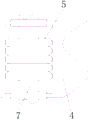
FIG. 5 is a schematic top view of the connection structure of the movable rod and the scroll damping spring according to the embodiment.
In the figure: 1. a curtain wall body; 2. a support bar; 3. connecting blocks; 4. a movable rod; 5. a scroll damping spring; 6. a first connecting shaft; 7. a second connecting shaft; 8. a movable block; 9. fixing the rod; 10. mounting a plate; 11. a first damping spring; 12. a support block; 13. a second damping spring; 14. and a limiting block.
Detailed Description
The technical solutions in the embodiments of the present invention will be clearly and completely described below with reference to the drawings in the embodiments of the present invention, and it is obvious that the described embodiments are only a part of the embodiments of the present invention, and not all of the embodiments. All other embodiments, which can be derived by a person skilled in the art from the embodiments given herein without making any creative effort, shall fall within the protection scope of the present invention.
Examples
Referring to fig. 1-5, a building curtain wall with wind resistance function includes a curtain wall body 1; curtain body 1's one side fixedly connected with bracing piece 2, bracing piece 2's outer wall fixedly connected with connecting block 3, the inside swing joint of connecting block 3 has movable rod 4, the both ends inner wall fixedly connected with spiral damping spring 5 of movable rod 4, spiral damping spring 5's inner wall is first connecting axle 6 of fixedly connected with and second connecting axle 7 respectively, the both ends fixedly connected with movable block 8 of second connecting axle 7.
The inside swing joint of one end of movable block 8 has dead lever 9, and the both ends fixedly connected with mounting panel 10 of dead lever 9, the outer wall swing joint of dead lever 9 have first damping spring 11, one side inner wall fixedly connected with supporting shoe 12 of mounting panel 10, the inner wall fixedly connected with second damping spring 13 of supporting shoe 12, and bracing piece 2 stretches into the inside one end fixedly connected with stopper 14 of supporting shoe 12.
When the curtain wall body 1 works, when the curtain wall body 1 is impacted by external force, the supporting rod 2 is pushed to slide, so that the supporting rod 2 pushes one end of the second connecting shaft 7 to incline and push the scroll damping spring 5 to deform through the connecting block 3 and the first connecting shaft 6, the other end of the movable rod 4 pushes the scroll damping spring 5 to deform and pushes the movable block 8 to slide through the second connecting shaft 7, so that the impact force is preliminarily buffered under the elastic action of the scroll damping spring 5, meanwhile, the movable block 8 pushes the first damping spring 11 on the outer wall of the fixed rod 9 to contract and deform when sliding, so that the impact force is further buffered under the elastic action of the first damping spring 11, meanwhile, the supporting rod 2 pushes the second damping spring 13 inside the supporting block 12 to contract and deform through the limiting block 14 when sliding, so that deeper buffering is performed under the elastic action of the second damping spring 13, and then realized carrying out the resistance to compression to multistage strong wind, improved application scope.
In this embodiment, connecting block 3 is at the outer wall symmetric distribution of bracing piece 2, and the inner wall of connecting block 3 and the both ends fixed connection of first connecting axle 6, has made things convenient for bracing piece 2 to drive both ends connecting block 3 and slide when sliding to make connecting block 3 promote the movable rod 4 at both ends through first connecting axle 6 and slope.
In this embodiment, connecting block 3 and the one side that the movable block 8 is close to each other are overlooked and are regarded as "concave" font structure, and connecting block 3 and the width of the recess of movable block 8 are greater than the width of movable rod 4, have guaranteed that movable rod 4 is effectual rotates in connecting block 3 and the inside of movable block 8.
In this embodiment, the both ends of movable rod 4 are passed through scroll damping spring 5 and are constituted revolution mechanic with first connecting axle 6 and second connecting axle 7 respectively, and just the looking of movable rod 4 is the slope setting to make movable rod 4 drive scroll damping spring 5 deformation when rotatory, and then carry out preliminary buffering through scroll damping spring 5's elasticity.
In this embodiment, one side of the movable block 8 and one end fixed connection of the first damping spring 11, and the movable block 8 constitutes a telescopic structure through the first damping spring 11 and the fixed rod 9, thereby being favorable for further buffering through the elasticity of the first damping spring 11.
In this embodiment, the fixed rod 9 and the movable block 8 are connected in a penetrating manner, and the movable block 8 forms a sliding structure with the mounting plate 10 through the fixed rod 9, so that the stability of the movable block 8 during sliding is ensured.
In this embodiment, one end of the second damping spring 13 is fixedly connected to one side of the limiting block 14, and the limiting block 14 forms a telescopic structure with the supporting block 12 through the second damping spring 13, so that the second damping spring 13 can be used for more deeply buffering.
In this embodiment, the diameter of stopper 14 is greater than the diameter of bracing piece 2, and is "T" font distribution between stopper 14 and the bracing piece 2, has avoided the inside phenomenon of bracing piece 2 roll-off supporting shoe 12.
In conclusion, this building curtain wall with anti-wind function has realized tertiary shock-absorbing function to solve current poor shock-absorbing capacity's problem, make then whole have carry out the function of resistance to compression to multistage strong wind, improved application scope, and prolonged life, further satisfied people's user demand, be worth using widely.
In the description herein, references to the description of "one embodiment," "an example," "a specific example" or the like are intended to mean that a particular feature, structure, material, or characteristic described in connection with the embodiment or example is included in at least one embodiment or example of the utility model. In this specification, the schematic representations of the terms used above do not necessarily refer to the same embodiment or example. Furthermore, the particular features, structures, materials, or characteristics described may be combined in any suitable manner in any one or more embodiments or examples.
The foregoing shows and describes the general principles, essential features, and advantages of the utility model. It will be understood by those skilled in the art that the present invention is not limited to the embodiments described above, which are described in the specification and illustrated only to illustrate the principle of the present invention, but that various changes and modifications may be made therein without departing from the spirit and scope of the present invention, which fall within the scope of the utility model as claimed.