Decorative profile and profile decorative wall structure
Technical Field
The utility model relates to the field of wall decoration, in particular to a decorative section bar and a section bar decorative wall structure.
Background
After the outer wall and the inner wall of the building are poured or bricked, the wall surface needs to be decorated. At this time, a wall wrapping treatment mode is generally adopted, namely, plates are paved on the outer side of the wall surface. However, the current wall wrapping method has the following defects: 1) when a plurality of plates are required to be sequentially arranged and laid along the length or width direction of the wall surface, connecting pieces such as screws and the like are required to be connected with the wall surface at the edge of each plate, the number of required connecting pieces is large, and meanwhile, the installation consumes long time; 2) when the adjacent plates are not tightly spliced due to insufficient dimensional accuracy and a gap appears, the inner wall can be directly seen from the gap, and the visual effect is poor; 3) when lamps such as lamp strips and the like need to be arranged on part of the plate, the plate mold with different specifications is additionally developed, or the groove for mounting the lamp strips is formed in the original plate, so that the cost is high, and the flexibility of field mounting is low; 4) when stripes with different colors are required to be arranged on adjacent plates, a mode of painting on the plates is generally adopted, and the painting of narrow lines requires high precision and is high in cost.
SUMMERY OF THE UTILITY MODEL
The utility model aims to provide a decorative section and a section decorative wall surface structure, wherein the section main bodies of adjacent decorative sections can be spliced, the number of required connecting pieces with a wall body is small, and the mounting efficiency is high.
In order to achieve the purpose, the utility model provides a decorative profile, which comprises a profile main body, wherein the profile main body comprises a plate main body, one side of the plate main body is provided with a raised first inserting part, and the other side of the plate main body is provided with a concave decorative profile clamping groove; the first inserting part is matched with the decorative section clamping groove.
As a further improvement of the utility model, the section bar main body is also provided with a first supporting part which is arranged on one side of the decorative section bar clamping groove.
As a further improvement of the utility model, the decorative profile clamping groove comprises a first clamping groove and a second clamping groove which are sequentially arranged along the plugging direction of the first plugging part; the first clamping groove and the second clamping groove are communicated, and the width of the first clamping groove is larger than that of the second clamping groove.
In order to achieve the above object, the present invention further provides a profile decorative wall structure, comprising at least two profile main bodies, each profile main body being arranged in sequence; between adjacent section bar main bodies, the first inserting part of one section bar main body is inserted and matched with the decorative section bar clamping groove of the other section bar main body.
As a further improvement of the utility model, the device also comprises an intermediate piece positioned between two adjacent profile main bodies; one side of the middle piece is provided with a second inserting part, and the other side of the middle piece is provided with a third clamping groove; the second inserting part of the middle piece is in inserting fit with the decorative section bar clamping groove of one section bar main body, and the third clamping groove of the middle piece is in inserting fit with the first inserting part of the other section bar main body.
As a further improvement of the utility model, the decorative profile clamping groove comprises a first clamping groove and a second clamping groove which are sequentially arranged along the plugging direction of the first plugging part; the first clamping groove is communicated with the second clamping groove, and the width of the first clamping groove is larger than that of the second clamping groove; the width of the first inserting part is matched with that of the second clamping groove, and the width of the second inserting part of the middle piece is matched with that of the first clamping groove.
As a further development of the utility model, a gap is left between the plate bodies of the adjacent profile bodies.
As a further improvement of the utility model, a lamp is embedded in the gap; the lamp is in a lamp strip structure.
As a further development of the utility model, a gap is left between the plate bodies of the adjacent profile bodies, the intermediate piece being located at the bottom of the gap; the intermediate piece is provided with a second supporting part.
As a further improvement of the utility model, the profile comprises profile bodies which are mutually angled and adjacently arranged, and the adjacently arranged profile bodies are connected through a corner profile.
Advantageous effects
Compared with the prior art, the decorative section bar and the section bar decorative wall surface structure have the advantages that:
1. the plate main part of adjacent decoration section bar is pegged graft each other through first grafting portion and decoration section bar draw-in groove and is realized fixing, then reducible required connection decorate section bar and wall if connecting piece such as screw, only need be equipped with in the plate main part decorate one side of section bar draw-in groove beat the screw can, and one side that is equipped with first grafting portion in the plate main part also can not the perk under the restriction of decorating the section bar draw-in groove, fixed effect is good, splicing efficiency improves by a wide margin. In addition, even if the size error of the decorative section bar is a little big, the gap between the adjacent plate main bodies is still blocked by the first inserting part, human eyes can not see the inner wall body directly through the gap, and the visual effect is better.
2. The first supporting part of the section bar main body is pressed on the wall surface, so that the positioning effect can be achieved, and the flatness of the decorative wall surface after the wall is wrapped is ensured. The screw can pass through the first supporting part and can not be exposed after being covered by another decorative section bar, and the attractiveness of the decorative wall surface is not affected.
3. Through increasing the middleware between adjacent two section bar main parts, can let and form great space between the adjacent plate main part, can install the lamp area, the lamp area can be basically with plate main part parallel and level moreover, ensures that the decorative wall face levels. In addition, when the middleware is located the bottom in this space, through letting middleware and plate main part adopt different colours, can form the stripe pattern at the decorative wall face, improve the aesthetic property, need not to adopt the mode preparation stripe that sprays paint simultaneously, it is with low costs.
The utility model will become more apparent from the following description when taken in conjunction with the accompanying drawings, which illustrate embodiments of the utility model.
Drawings
In order to more clearly illustrate the embodiments of the present invention or the technical solutions in the prior art, the drawings used in the description of the embodiments or the prior art will be briefly described below, it is obvious that the drawings in the following description are only some embodiments of the present invention, and for those skilled in the art, other drawings can be obtained according to the drawings without creative efforts.
FIG. 1 is a sectional view of a decorative profile in example 1;
FIG. 2 is a sectional view of the sectional material decorative wall structure of example 1;
FIG. 3 is a sectional view of an intermediate member in embodiment 2;
FIG. 4 is a sectional view of the sectional material decorative wall structure of example 2;
FIG. 5 is a sectional view of the sectional material decorative wall structure of example 3;
FIG. 6 is a sectional view of the decorative profile of example 4;
FIG. 7 is a sectional view of an intermediate member in embodiment 4;
FIG. 8 is a sectional view of the section bar-decorated wall surface structure of example 4;
FIG. 9 is a sectional view of a corner profile in example 4;
FIG. 10 is a schematic view showing the joining of the corner section and the finishing section in example 4;
FIG. 11 is a sectional view of a corner profile in example 5;
fig. 12 is a schematic view of the joining of the corner section and the decorative section in example 5.
Detailed Description
Embodiments of the present invention will now be described with reference to the accompanying drawings.
Example 1
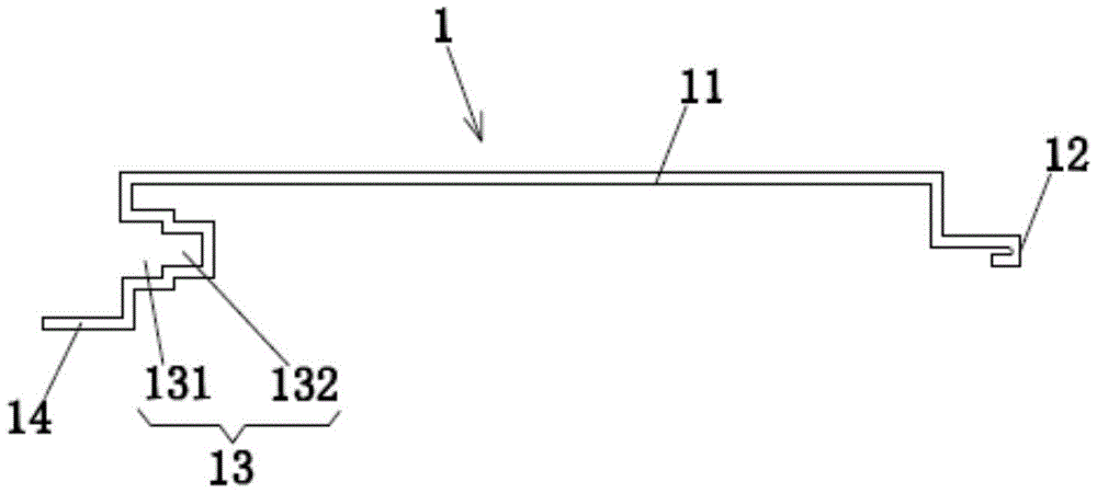
The specific embodiment of the present invention is shown in fig. 1, which is a decorative profile, and includes a profile main body 1, where the profile main body 1 includes a plate main body 11, one side of the plate main body 11 is provided with a convex first inserting portion 12, and the other side of the plate main body 11 is provided with a concave decorative profile clamping groove 13. The first plug-in part 12 is adapted to the decorative profile slot 13.
As shown in fig. 2, the profile body 1 is further provided with a first supporting portion 14, and the first supporting portion 14 is disposed outside the decorative profile clamping groove 13. When installed, the first support portion 14 is supported on a wall surface and then fixed by screws. The other profile body 1 covers the outside of the first support 14 of this profile body 1, without the first support 14 and the screws being exposed. In addition, when the first supporting portion 14 is not provided, the screw may also pass through a side of the plate body 11 near the trim profile slot 13 and be connected with the wall, but other covering methods are needed to hide the screw.
In this embodiment, the decorative profile slot 13 includes a first slot 131 and a second slot 132 sequentially arranged along the plugging direction of the first plugging portion 12. The first card slot 131 and the second card slot 132 are both communicated, and the width of the first card slot 131 is greater than that of the second card slot 132.
Fig. 2 shows a first splicing type sectional material decorative wall structure, which includes at least two sectional material main bodies 1, wherein the sectional material main bodies 1 are arranged in sequence. Between adjacent profile main bodies 1, a first inserting part 12 of one profile main body 1 is directly inserted and matched with a decorative profile clamping groove 13 of the other profile main body 1.
The splicing method of the section bar decorative wall surface in the embodiment comprises the following steps: at least two section bar main bodies 1 provided with plate main bodies 11 are sequentially arranged along the wall surface, the adjacent section bar main bodies 1 are directly spliced and matched through a first splicing part 12 and a decorative section bar clamping groove 13, and the plate main bodies 11 and the wall body are mutually fixed. After splicing, the plate bodies 11 of adjacent profile bodies 1 are located on the same plane.
Example 2
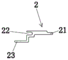
As shown in fig. 3 and 4, the difference from embodiment 1 is that the profile decorated wall structure further includes an intermediate member 2 located between two adjacent profile bodies 1. The intermediate piece 2 is also of profile construction. The middle part 2 is provided with a second inserting part 21 at one side and a third clamping groove 22 at the other side. The second plug-in part 21 of the intermediate part 2 is in plug-in fit with the decorative profile slot 13 of one of the profile bodies 1, and the third slot 22 of the intermediate part 2 is in plug-in fit with the first plug-in part 12 of the other profile body 1.
The ornamental-profile fastening groove 13 includes a first fastening groove 131 and a second fastening groove 132 that are sequentially arranged along the insertion direction of the first insertion portion 12. The first card slot 131 and the second card slot 132 are both communicated, and the width of the first card slot 131 is greater than that of the second card slot 132. The width of the first plug part 12 is matched with the second card slot 132 and matched with the third card slot 22; the width of the second plug-in part 21 of the middle part 2 is matched with that of the first slot 131.
In this embodiment, when the section decorative wall surface is spliced, the intermediate member 2 is inserted between the insertion fitting portions of the adjacent section main bodies 1, so that a gap 3 is formed between the edges of the plate main bodies 11 of the adjacent section main bodies 1, as shown in fig. 4. Let middleware 2 be located the bottom in space 3, wherein, middleware 2 and plate main part 11 both colors have the difference, then middleware 2's color can be discerned by people's eye, forms the stripe structure, improves pleasing to the eye effect.
Example 3
As shown in fig. 5, the difference from embodiment 2 is that a lamp 4 is embedded in the gap 3. In this embodiment, the lamp 4 is a lamp strip structure. The top surface of the lamp strip structure and the plate body 11 are located on the same plane.
Example 4
As shown in fig. 6 to 10, the difference from the embodiments 2 and 3 is that the sectional shape of the intermediate member 2 is different. To fit the intermediate piece 2 in this embodiment, the width of the decorative profile slot 13 is uniform in the plugging direction. The intermediate member 2 is provided with a second support portion 23. The second support portion 23 is located on the side of the intermediate member 2 close to the third notch 22. The second support portion 23 is also supported on the wall surface and is connected to the wall surface by screws. The second support 23 is covered by the adjacent profile body 1 and the first support plate 14 is covered by the adjacent intermediate piece 2.
In addition, the plate body 11 of the profile body 1 can also be provided with decorative grooves 15. The decorative groove 15 can be provided with a lamp strip.
As shown in fig. 10, the profile decorative wall surface may further include profile main bodies 1 which are mutually angled and adjacently arranged, and the adjacently arranged profile main bodies 1 are connected through a corner profile 5. The two sides of the corner section bar 5 are both provided with fourth clamping grooves 51, and the corner section bar 5 is also provided with a third supporting part 52 matched with a corner. The profile main bodies 1 on both sides of the corner profile 5 are in inserted fit with the fourth clamping grooves 51 of the corner profile 5 through the first inserting parts 12.
Example 5
As shown in fig. 11 to 12, the difference from embodiment 4 is that the cross-sectional shape of the corner profile 5 is different. In addition, the profile body 1 on one side of the corner profile 5 is in plug-in fit with the fourth locking groove 51 of the corner profile 5 via the first plug-in part 12. The other side of the angle section 5 is adjacent to the side of the other section main body 1 provided with the decorative section clamping groove 13, and the side of the angle section 5 presses the side of the section main body 1 to the wall body through the outer pressing plate for limiting, as shown in fig. 12.
The present invention has been described in connection with the preferred embodiments, but the present invention is not limited to the embodiments disclosed above, and is intended to cover various modifications, equivalent combinations, which are made in accordance with the spirit of the present invention.