Switch valve core, switching valve and shower device
Technical Field
The utility model relates to the field of valves, in particular to a switching valve core, a switching valve and a shower device.
Background
In the switching valve of the prior art, as described in CN2888209Y, two ends of a valve rod in a valve core are provided with two large piston heads and two small piston heads, and the two piston heads open and close two water outlets respectively, when one of the water outlets is opened or closed, pressure of the water outlet is maintained or released, and a pressure difference generated by a difference between water pressure areas of the large piston head and the small piston head pushes the valve rod to move, so as to realize switching of water outlet between the two water outlets. Adopt this switching structure must guarantee that the valve rod both ends receive the water pressure area to have sufficient area poor, just can guarantee that the valve rod produces the displacement, just so require the valve rod tip relatively less, nevertheless in order to guarantee that the play water flow of valve rod tip is big enough, then require the valve rod displacement volume great in order to realize that the water opening is big enough, this displacement demand that just needs the switch case to set up great space and satisfy the valve rod, make switch case and diverter valve occupation space big, can not use on the product that the volume is less.
SUMMERY OF THE UTILITY MODEL
The present application aims to overcome the above-mentioned defects or problems existing in the background art, and provides a switching valve core, a switching valve and a shower device, which can ensure the completion of the switching action of a water outlet under the condition of small valve rod displacement, the switching valve core, the switching valve and the shower device using the switching valve have reliable water outlet switching action, the switching valve core and the switching valve have small volume and large flow.
In order to achieve the purpose, the following technical scheme is adopted:
the first technical scheme relates to a switching valve core, which comprises a body, a plugging component, a first elastic piece and a valve rod component, wherein the plugging component is slidably arranged in a valve cavity of the body and divides the valve cavity into a pressure relief cavity and a water passing cavity which are communicated with each other; the body is provided with a water inlet, a first water outlet and a second water outlet which are communicated with the water passing cavity, and a pressure relief port which is communicated with the pressure relief cavity; the first elastic piece is arranged in the pressure relief cavity and supports the plugging component to plug the second water outlet; the valve rod assembly is arranged in the valve cavity in a sliding mode and is provided with a pressure bearing part and a plug of which the water pressure bearing area is smaller than that of the pressure bearing part; when the pressure of the first water outlet is released, the pressure release opening is plugged by the plug; when the first water outlet maintains pressure, the pressure relief opening is opened by the plug, and the water pressure in the water passing cavity drives the plugging component to overcome the elastic force of the first elastic part to open the second water outlet.
The second technical scheme is based on the first technical scheme, wherein, the body includes disk seat and lower disk seat, go up the disk seat and pass through the buckle with lower disk seat and be connected, surround and form the valve pocket, the pressure release mouth is seted up in go up the disk seat, water inlet, first delivery port and second delivery port are seted up in lower disk seat.
The third technical scheme is based on the first technical scheme, wherein the valve rod assembly comprises a valve rod, a pressure bearing part and a plug, the valve rod penetrates through the pressure relief cavity, the blocking assembly and the water passing cavity, and a gap is formed between the valve rod and the blocking assembly to communicate the water passing cavity and the pressure relief cavity.
The fourth technical scheme is based on the first technical scheme, wherein when the first water outlet is depressurized, the pressure bearing part is far away from the pressure relief opening, and the plug is close to the first water outlet; when the first water outlet is used for maintaining pressure, the plug is far away from the first water outlet, and the pressure bearing part is close to the pressure relief opening.
The fifth technical scheme is based on the fourth technical scheme, and the pressure relief device further comprises a second elastic piece, wherein the second elastic piece is arranged between the body and the pressure bearing portion and provides elastic force for the plug to plug the pressure relief opening.
A sixth technical scheme is based on any one of the first to fifth technical schemes, wherein the plugging assembly comprises a sliding seat, a sealing gasket, a sealing ring and a buckle cover, the sliding seat is in sliding fit with the body, and the sealing gasket is clamped on the lower end surface of the sliding seat and used for plugging the second water outlet; the sealing ring is sleeved on the outer edge of the upper end face of the sliding seat and used for sealing a gap between the sliding seat and the inner wall of the valve cavity; the buckle cover is connected with the sliding seat in a buckling mode and used for fixing the sealing ring on the sliding seat.
A seventh technical means is based on the sixth technical means, wherein the valve rod penetrates through the sliding seat, and a gap is formed between the valve rod and the sliding seat so as to communicate the water passing cavity and the pressure relief cavity.
An eighth technical solution is based on the sixth technical solution, wherein the first elastic member is a spring, and the spring is installed between the upper valve seat and the sliding seat.
The ninth technical means is based on the sixth technical means, wherein the pressure bearing portion is in threaded connection with one end of the valve rod, and the other end of the pressure bearing portion forms a bolt head.
A tenth technical aspect relates to a switching valve, including: a switching spool as described in any one of the first to ninth aspects; the valve shell is provided with a valve shell inner cavity, and a water inlet channel, a first water outlet channel and a second water outlet channel which are communicated with the valve shell inner cavity; the switching valve core is arranged in an inner cavity of the valve shell, the water inlet channel is communicated with the water inlet, the first water outlet channel is communicated with the first water outlet, and the second water outlet is communicated with the pressure relief port.
An eleventh technical aspect relates to a shower apparatus, which includes: a switching valve as defined in the tenth aspect; the top shower head is communicated with the second water outlet channel of the switching valve and is used for fixing water flow sprayed downwards from the top; the handheld shower head is used for facilitating a bather to spray water flow to the body by holding the shower head by hands; and one end of the handheld shower switch is communicated with the first water outlet channel of the switching valve, and the other end of the handheld shower switch is communicated with the handheld shower for controlling the on-off of the water outlet of the handheld shower.
Compared with the prior art, the technical scheme has the following beneficial effects:
in the first technical scheme, the plug (the end with the smaller water pressure area) of the valve rod assembly is set to open and close the pressure relief opening instead of directly opening and closing the water outlet, so that the displacement of the plug (the end with the smaller water pressure area) is not limited by the requirement of water yield; the plug is only used for opening and closing the pressure relief opening, the pressure in the pressure relief cavity is reduced by opening the pressure relief opening, and the second water outlet is opened by the plugging component under the action of the pressure difference between the water passing cavity and the pressure relief cavity, so that the water outlet of the second water outlet is switched by the action of the valve rod component. Therefore, the switching of the water outlet is realized, the large displacement of the valve rod assembly is not needed, and the volume of the valve core is effectively reduced.
In the second technical scheme, the body structure of the upper valve seat and the lower valve seat is adopted, so that the structure arrangement and the assembly of other valve core components are facilitated.
In the third technical scheme, the valve rod penetrates through the pressure relief cavity, the plugging component and the water passing cavity, and a gap is formed between the valve rod and the plugging component to communicate the water passing cavity and the pressure relief cavity, so that the pressure difference between the water passing cavity and the pressure relief cavity is ensured under the condition that the pressure of the pressure relief cavity is released, the plugging component is driven, and the action control is effectively realized.
In the fourth technical scheme, the pressure-bearing part and the plug are arranged in an optimal structure, so that the linkage of the pressure-bearing part and the plug and the reduction of the volume of the valve core are facilitated.
In the fifth technical scheme, the second elastic piece is arranged between the body and the pressure-bearing part, so that the elastic restoring force is provided for the plug to plug the pressure relief opening, and the structure is simple.
In the sixth technical scheme, the plugging component is arranged by adopting the structure of the sliding seat, the sealing gasket, the sealing ring and the buckle cover, the sliding fit relation between the plugging component and the body and the sealing between the plugging component and the inner wall of the body are convenient to realize, the structure is simple to arrange, and the volume of the valve core is reduced.
In the seventh technical scheme, the valve rod penetrates through the sliding seat and forms a gap with the sliding seat, so that the pressure difference between the water passing cavity and the pressure relief cavity is ensured under the condition that the pressure relief cavity is used for pressure relief, the valve rod assembly is guided, and the plug is convenient to accurately plug the pressure relief opening.
In the eighth technical scheme, the spring is adopted as the elastic part, the structure is simple to set, and the cost is low.
In the ninth technical scheme, the pressure-bearing part is in threaded connection with one end of the valve rod, and the other end of the pressure-bearing part forms a bolt head structure, so that the pressure-bearing part can be assembled conveniently.
In the tenth technical solution, in addition to the above technical effects, the gap formed between the switching valve element and the inner wall of the valve housing enables the second water outlet to communicate with the second water outlet channel, so that a water channel of the second water outlet does not need to be additionally provided, and the overall structure of the switching valve is more compact.
In the eleventh technical scheme, besides the technical effects, the shower head can be conveniently switched between the handheld shower head and the top shower head to discharge water during the shower process.
Drawings
In order to more clearly illustrate the technical solution of the embodiments, the drawings needed to be used are briefly described as follows:
FIG. 1 is a perspective view of a shower apparatus according to an embodiment;
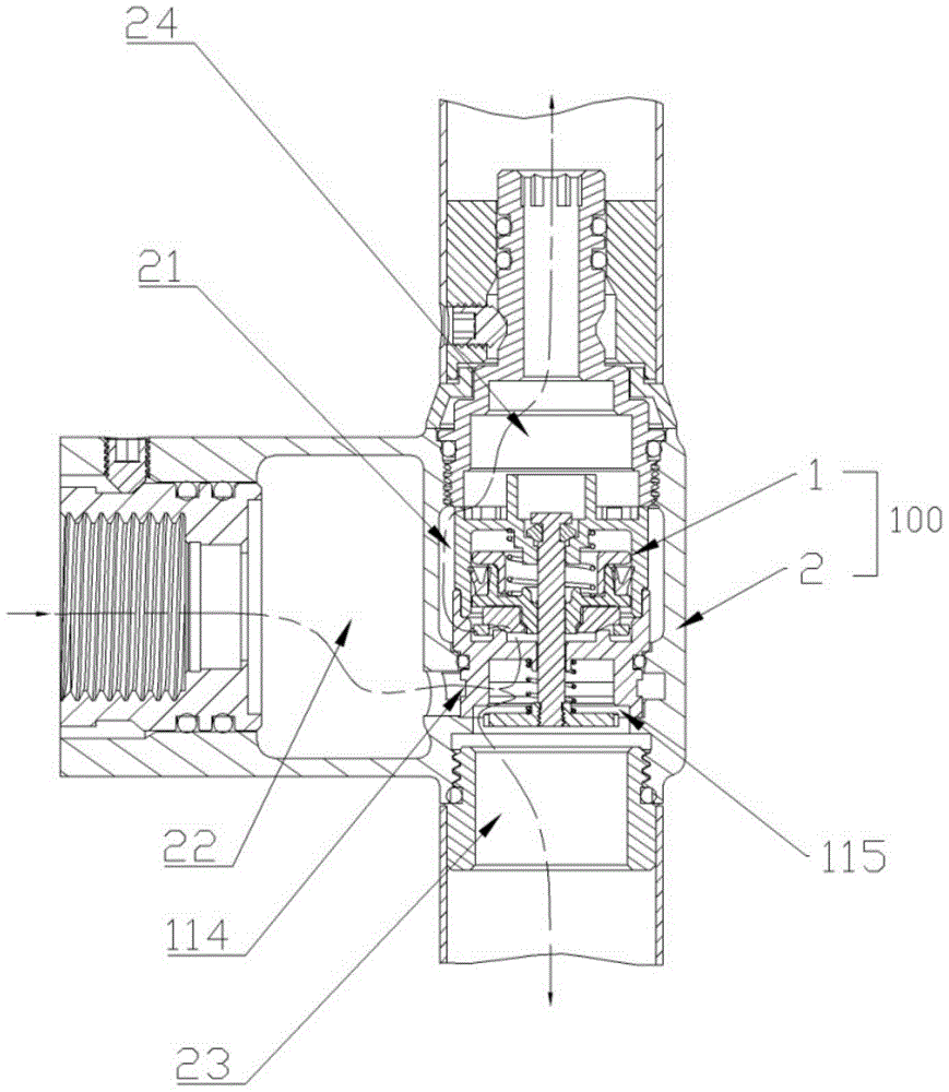
FIG. 2 is a sectional view of a switching valve in the embodiment;
FIG. 3 is an exploded perspective view of the switching spool of the embodiment;
FIG. 4 is an isometric view of the switch spool of the embodiment;
FIG. 5 is a front sectional view of the switching spool in the embodiment;
FIG. 6 is a top view of the switch spool of the embodiment;
FIG. 7 is a cross-sectional view of the switching spool A-A of the embodiment shown in the first position;
FIG. 8 is a sectional view of the switching spool A-A in the second embodiment.
Description of the main reference numerals:
a shower apparatus 1000; a switching valve 100; a top shower 200; a hand-held shower head 300; a hand-held shower switch 400;
a switching valve core 1; the valve comprises a body 11, an upper valve seat 111, a lower valve seat 112, a valve cavity 113, a pressure relief cavity 1131, a water passing cavity 1132, a water inlet 114, a first water outlet 115, a second water outlet 116 and a pressure relief opening 117; the plugging component 12, a sliding seat 121, a sealing gasket 122, a sealing ring 123 and a buckle cover 124; a first elastic member 13; the valve rod assembly 14, the valve rod 141, the bearing portion 142, the plug 143 and the bolt head 144; a second elastic member 15; an O-ring 16;
a valve housing 2, a housing interior 21; a water inlet passage 22; a first water outlet channel 23; a second water outlet channel 24.
Detailed Description
In the claims and specification, unless otherwise specified the terms "first", "second" or "third", etc., are used to distinguish between different items and are not used to describe a particular order.
In the claims and specification, unless otherwise specified, the terms "central," "lateral," "longitudinal," "horizontal," "vertical," "top," "bottom," "inner," "outer," "upper," "lower," "front," "rear," "left," "right," "clockwise," "counterclockwise," and the like are used in the orientation and positional relationship indicated in the drawings and are used for ease of description only and do not imply that the referenced device or element must have a particular orientation or be constructed and operated in a particular orientation.
In the claims and the specification, unless otherwise defined, the terms "fixedly" or "fixedly connected" are to be understood in a broad sense as meaning any connection which is not in a relative rotational or translational relationship, i.e. including non-detachably fixed connection, integrally connected and fixedly connected by other means or elements.
In the claims and specification, unless otherwise defined, the terms "comprising", "having" and variations thereof mean "including but not limited to".
The technical solution in the embodiments will be clearly and completely described below with reference to the accompanying drawings.
Referring to fig. 1, fig. 1 shows a shower apparatus 1000 in an embodiment. As shown in fig. 1, the shower apparatus 1000 includes a switching valve 100, a top shower 200, a hand shower 300, and a hand shower switch 400.
As shown in fig. 2, the switching valve 100 includes a switching valve spool 1 and a valve housing 2;
as shown in fig. 3 to 8, the switching spool 1 includes a body 11, a blocking assembly 12, a first elastic member 13, and a stem assembly 14. The body 11 includes an upper valve seat 111 and a lower valve seat 112, the upper valve seat 111 is provided with a pressure relief opening 117, the lower valve seat 112 is provided with a water inlet 114, a first water outlet 115 and a second water outlet 116, and the upper valve seat 111 is connected with the lower valve seat 112 in a buckling manner to form a valve cavity 113 in a surrounding manner. The plugging component 12 is disposed in the valve cavity 113 and includes a sliding seat 121, a sealing gasket 122, a sealing ring 123 and a fastening cover 124, the sliding seat 121 is in sliding fit with the body 11 to divide the valve cavity 113 into a pressure relief cavity 1131 and a water passing cavity 1132, the pressure relief cavity 1131 is communicated with the pressure relief opening 117, and the water passing cavity 1132 is communicated with the water inlet 114, the first water outlet 115 and the second water outlet 116. The sealing gasket 122 is clamped on the lower end surface of the sliding seat 121 and is used for sealing the second water outlet 116; the sealing ring 123 is sleeved on the outer edge of the upper end face of the sliding seat 121 and is used for sealing a gap between the sliding seat 121 and the inner wall of the valve cavity 113; the cover 124 is connected to the sliding seat 121 by a snap fit, and covers the sliding seat 121 to fix the seal ring 123 on the sliding seat 121, so that the seal ring 123 does not fall off the sliding seat 121. The first elastic element 13, which is a spring in this embodiment, is disposed in the pressure relief cavity 1131, and has one end abutting against the valve seat 111 and the other end abutting against the sliding seat 121, so as to provide an elastic force for the sealing pad 122 clamped on the sliding seat 121 to seal the second water outlet 116. The valve rod assembly 14 comprises a valve rod 141, a pressure bearing part 142 and a plug 143, wherein the valve rod 141 passes through the pressure relief cavity 1131, the sliding seat 121 and the water passing cavity 1132, and forms a gap with the sliding seat 121 to communicate the pressure relief cavity 1131 and the water passing cavity 1132; one end of the valve rod 141 is in threaded connection with the pressure-bearing portion 142, the pressure-bearing portion 142 is arranged at the first water outlet 115, the other end of the valve rod 141 is clamped with the plug 143 and extends to form a bolt head 144, the bolt head 144 facilitates assembly of the pressure-bearing portion 142, the plug 143 is used for opening and closing the pressure relief opening 117, and the water pressure bearing area of the plug 143 is smaller than that of the pressure-bearing portion 142. In this embodiment, it is preferable that a second elastic member 15 is further provided, where the second elastic member 15 is a spring, and is disposed in the water passing cavity 1132, one end of the spring abuts against the lower valve seat 112, and the other end of the spring abuts against the pressure bearing portion 142, so as to provide an elastic force for the plug 143 to plug the pressure relief opening 117, and ensure that the plug 143 can still plug the pressure relief opening 117 under the condition that the water pressure in the water passing cavity 1132 is low, that is, under the condition that the pressure difference generated by the water pressure received by the pressure bearing portion 142 and the plug 143 due to the low water pressure of the incoming water is not enough to drive the plug 143 to plug the pressure relief opening 117, thereby ensuring that the top shower head 200 does not leak water.
The valve casing 2 is in a three-way pipe shape and is provided with a valve casing inner cavity 21, and a water inlet passage 22, a first water outlet passage 23 and a second water outlet passage 24 which are communicated with the valve casing inner cavity 21.
As shown in fig. 2, the assembled switching valve 100 has the switching valve core 1 installed in the inner cavity 21 of the valve housing, the water inlet passage 22 communicated with the water inlet 114, the first water outlet passage 23 communicated with the first water outlet 115, and a water passage formed between the switching valve core 1 and the inner wall of the valve housing 2, so that the second water outlet 116 is communicated with the second water outlet passage 24; an O-shaped sealing ring 16 is arranged between the lower valve seat 112 and the inner wall of the valve casing 2 and is used for preventing water in the water inlet channel 22 from being communicated with the second water outlet 116 and the second water outlet channel 24 through a gap between the switching valve core 1 and the inner wall of the valve casing 2; the pressure relief port 117 is communicated with the second water outlet channel 24, so that the second water outlet 116, the pressure relief port 117 and the second water outlet channel 24 are communicated, and the inner cavity of the valve shell is provided with a water channel for communicating the second water outlet with the second water outlet channel, so that the whole structure of the switching valve is more compact.
In the assembled shower device 1000, the water inlet channel 22 of the switching valve 100 supplies cold water and hot water, the second water outlet channel 24 is communicated with the top shower 200, one end of the hand-held shower switch 400 is communicated with the first water outlet channel 23, and the other end is communicated with the hand-held shower 300, so as to control the on-off of the water outlet of the hand-held shower 300. When the switching valve 100 is supplied with cold and hot water, and the hand-held shower switch 400 is in an open state, the pressure of the first water outlet 115 is released, since the area of the pressure bearing portion 142 under the pressure is larger than that of the plug 143, and the pressure borne by the pressure bearing portion 142 is larger than that of the plug 143, the pressure difference pushes the valve rod assembly 14 to move integrally, in this embodiment, the pressure bearing portion 142 moves towards the direction away from the pressure relief opening 117, and drives the plug 143 to move towards the direction close to the first water outlet 115, so as to block the pressure relief opening 117, and water flows out from the first water outlet 115, passes through the first water outlet channel 23 and the hand-held shower switch 400, and is ejected from the hand-held shower 300. If a user needs to switch the water outlet mode, the top-spraying shower head 200 is changed to discharge water, and only the hand-held shower head switch 400 needs to be pressed to close the water outlet of the hand-held shower head 300, at this time, the first water outlet 115 maintains pressure, the second water outlet 116 and the pressure relief opening 117 release pressure, the pressure applied to the plug 143 is greater than that of the pressure-bearing part 142, and the pressure difference pushes the valve rod assembly 14 to move integrally, in this embodiment, the plug 143 moves away from the first water outlet 115 to drive the pressure-bearing part 142 to move toward the pressure relief opening 117, the plug 143 opens the pressure relief opening 117, once the pressure in the pressure relief cavity 1131 is reduced, the pressure in the pressure relief cavity 1131 is less than that in the water passing cavity 1132, because the two end surfaces of the pressure relief cavity 1131 and the water passing cavity 1132 of the plug assembly 12, the plug assembly 12 overcomes the elastic force of the first elastic member 13 to move toward the pressure relief opening 117 under the action of the pressure difference between the water passing cavity 1132 and the pressure relief cavity 1131, the plugging component 12 opens the second water outlet 116, and after water flows out from the second water outlet 116, the water is sprayed out from the top shower 200 through the waterway channel formed between the switching valve element 1 and the inner wall of the valve housing 2 and the second water outlet channel 24, so as to meet the requirement of the shower person for water outlet from the top. When the handheld shower 300 needs to be switched back to discharge water, the handheld shower switch 400 is turned on, the pressure of the first water outlet 115 is released, the pressure on the pressure bearing part 142 is greater than that of the plug 143, and the pressure bearing part 142 moves towards the direction far away from the pressure relief opening 117 to drive the plug 143 to plug the pressure relief opening 117; in case the pressure relief port 117 is plugged, the pressure in the pressure relief cavity 1131 and the pressure difference in the water passing cavity 1132 are reduced, the pressure difference between the water passing cavity 1132 and the pressure relief cavity 1131 borne by the plugging component 12 is reduced, the elastic force of the first elastic piece 13 props against the plugging component 12 to plug the second water outlet, the water outlet of the top shower head 200 is closed, and the water outlet is only carried out by the handheld shower head 300.
As can be seen from the above description, the plug 143 of the valve rod assembly 14 is configured to open and close the pressure relief opening 117, and the water outlet is not directly opened and closed, so that the displacement of the plug 143 is not limited by the requirement of the water output; the plug 143 is only for opening and closing the pressure relief opening 117, the pressure relief opening 117 performs a pressure relief function, the pressure relief opening 117 is opened to reduce the pressure in the pressure relief cavity 1131, the plugging component 12 opens the second water outlet 116 under the action of the pressure difference between the water passing cavity 1132 and the pressure relief cavity 1131, so that the water outlet of the second water outlet 116 is switched by the action of the valve rod component 14, and then the valve rod component 14 does not need a large displacement to meet the requirement of the water outlet amount, so that the volume of the switching valve core 1 can be effectively reduced, and the switching valve core 1 can be used on a product with a small volume. The valve rod 141 penetrates through the pressure relief cavity 1131, the plugging component 12 and the pressure relief cavity 1132, and forms a gap with the plugging component 12 to communicate with the structural arrangement of the pressure relief cavity 1132 and the pressure relief cavity 1131, so that the pressure difference between the pressure relief cavity 1131 and the pressure relief cavity 1132 can drive the plugging component 12 to slide, and the opening and closing of the second water outlet 116 can be effectively controlled. The bearing part 142 is arranged below the first water outlet 115, and the plug 143 is arranged above the pressure relief opening 117, so that the linkage between the bearing part 142 and the plug 143 and the installation of the second elastic element 15 are facilitated. The second elastic member 15 is disposed between the lower valve seat 112 and the pressure-bearing portion 142, so as to provide elastic restoring force for the plug 143 to block the pressure relief opening 117, and the structure is simple. The sliding seat 121 is configured to facilitate a sliding fit with the body 11. The valve rod 141 penetrates through the sliding seat 121 and forms a gap with the sliding seat 121, so that on one hand, the pressure difference between the water passing cavity 1132 and the pressure releasing cavity 1131 is ensured under the condition that the pressure of the pressure releasing cavity 1131 is released, and on the other hand, the valve rod assembly 14 is guided, so that the pressure releasing port 117 can be conveniently and accurately blocked by a plug. One end threaded connection of bearing portion 142 and valve rod 141, the other end forms the structural setting of a bolt head 144, is convenient for bearing portion 142 assembly and valve rod 141 wear to establish. The gap formed between the switching valve core 1 and the inner wall of the valve housing 2 enables the second water outlet 116 to communicate with the second water outlet channel 24, and a water outlet channel of the second water outlet 116 does not need to be additionally arranged, so that the switching valve 100 has a more compact overall structure and a smaller volume. The shower device is convenient for a bather to switch the hand-held shower head 300 and the top shower head 200 to discharge water in the shower process due to the installation of the switching valve with the structure, and the operation is easy.
The description of the above specification and examples is intended to be illustrative of the scope of the present application and is not intended to be limiting.