CN215683098U - Heat dissipation sheet and outdoor electrician instrument - Google Patents
Heat dissipation sheet and outdoor electrician instrument Download PDFInfo
- Publication number
- CN215683098U CN215683098U CN202122230038.6U CN202122230038U CN215683098U CN 215683098 U CN215683098 U CN 215683098U CN 202122230038 U CN202122230038 U CN 202122230038U CN 215683098 U CN215683098 U CN 215683098U
- Authority
- CN
- China
- Prior art keywords
- conducting plate
- heat conducting
- instrument
- box body
- heat
- Prior art date
- Legal status (The legal status is an assumption and is not a legal conclusion. Google has not performed a legal analysis and makes no representation as to the accuracy of the status listed.)
- Active
Links
- 230000017525 heat dissipation Effects 0.000 title claims description 9
- RYGMFSIKBFXOCR-UHFFFAOYSA-N Copper Chemical compound [Cu] RYGMFSIKBFXOCR-UHFFFAOYSA-N 0.000 claims description 7
- 229910052802 copper Inorganic materials 0.000 claims description 7
- 239000010949 copper Substances 0.000 claims description 7
- 239000000463 material Substances 0.000 claims description 7
- 239000003822 epoxy resin Substances 0.000 claims description 2
- 239000003292 glue Substances 0.000 claims description 2
- 229920000647 polyepoxide Polymers 0.000 claims description 2
- 239000000428 dust Substances 0.000 abstract description 12
- 238000000034 method Methods 0.000 abstract description 6
- 238000001816 cooling Methods 0.000 abstract description 4
- 230000000694 effects Effects 0.000 description 3
- 229910001220 stainless steel Inorganic materials 0.000 description 3
- 239000010935 stainless steel Substances 0.000 description 3
- 238000003466 welding Methods 0.000 description 3
- 238000012986 modification Methods 0.000 description 2
- 230000004048 modification Effects 0.000 description 2
- 239000004593 Epoxy Substances 0.000 description 1
- 238000004026 adhesive bonding Methods 0.000 description 1
- 230000033228 biological regulation Effects 0.000 description 1
Images


Landscapes
- Cooling Or The Like Of Electrical Apparatus (AREA)
Abstract
The utility model relates to a radiating fin and an outdoor electrical instrument, wherein the radiating fin comprises an inner heat conducting plate and an outer heat conducting plate which are respectively arranged on the inner side and the outer side of a box body of the instrument to be radiated, and one or more inner heat conducting plates are fixedly connected with the outer heat conducting plate. The instrument box body is provided with a mounting hole for the inner heat conducting plate to pass through; the outer heat conducting plate is fixedly connected with the outer surface of the instrument box body, and the inner heat conducting plate penetrates through the mounting hole to enter the instrument box body and is connected with a high-power element or a circuit board with high heat productivity in the instrument box body. The utility model is transmitted to the outer heat conducting plate through the inner heat conducting plate, and the heat on the outer heat conducting plate is dissipated into the air. The inner heat conducting plate and the outer heat conducting plate are respectively arranged on the inner side and the outer side of the instrument box body, and the instrument is a sealed whole and can effectively prevent dust from entering the instrument. Compared with the method for cooling by a fan in the prior art, the method for cooling the instrument by the fan does not cause dust to enter the instrument, does not need to clean the dust in the instrument regularly, and saves labor cost.
Description
Technical Field
The utility model relates to the technical field of electronic instruments, in particular to a radiating fin and an outdoor electrical instrument using the same.
Background
In the debugging process of transformer substation, there are many electrical equipment to install in the open air, these outdoor electrical equipment require to carry out relevant test according to the relevant regulation of country, when using electrician's instrument to carry out the test, electrician's instrument can generate heat, if electrician's instrument seriously generates heat can influence the accuracy of data, the current commonly used electrician is fan for the instruments fan cools down for electrician's instrument, because electrician's instrument has installed the fan, the dust can get into the inside of instrument through the fan mouth, especially when doing outdoor electrical equipment's test project, when using the instrument to work, the inside dust that gets into of instrument can not be avoided. The fan mouth of instrument usually all has the filter screen, and despite there is the filter screen, tiny dust still can get into the inside of instrument, and inside dust can lead to the instrument trouble, and in addition, the dust of the interior of instrument needs regularly to be cleared up to the electrician instrument commonly used, has increased the cost of labor.
Disclosure of Invention
The technical problem to be solved by the utility model is to provide a radiating fin and an outdoor electrical instrument, which can prevent dust from entering the interior of the instrument while reducing the temperature of the interior of the instrument.
In order to solve the above problems, according to an aspect of the present invention, there is provided a heat sink comprising an inner heat conducting plate and an outer heat conducting plate respectively disposed at inner and outer sides of an instrument box body to be heat dissipated, one or more inner heat conducting plates and outer heat conducting plates being fixedly connected; the inner heat conducting plate is used for connecting a heat dissipation element, and the outer heat conducting plate is used for dissipating heat to the outside of the instrument box body to be dissipated.
Furthermore, the section of the inner heat conducting plate is L-shaped and is provided with a first side and a second side which are perpendicular to each other, and the outer heat conducting plate is square; the first edge of the inner heat conducting plate is fixedly connected with the middle part of the outer heat conducting plate.
Furthermore, a round hole is formed in the second edge of the inner heat conducting plate, a screw is installed in the round hole, and the screw is in threaded connection with a nut connected with a grounding wire.
Further, the inner heat conducting plate and the outer heat conducting plate are both made of copper materials.
Furthermore, the thickness of the inner heat conducting plate is 1-3 mm, and the thickness of the outer heat conducting plate is 2-5 mm.
According to another aspect of the utility model, an outdoor electrical instrument is provided, which comprises an instrument box body and the radiating fins arranged on the box body, wherein the instrument box body is provided with a mounting hole for an inner heat conducting plate to pass through; the outer heat conducting plate is fixedly connected with the outer surface of the instrument box body, and the inner heat conducting plate penetrates through the mounting hole to enter the instrument box body and is connected with a high-power element or a circuit board with high heat productivity in the instrument box body.
Furthermore, the inner side surface of the outer heat conducting plate is fixedly adhered to the outer surface of the instrument box body through epoxy resin AB glue.
The utility model has simple structure and convenient use, the heat generated in the instrument is transferred to the outer heat conducting plate through the inner heat conducting plate, and the heat on the outer heat conducting plate is dissipated into the air. The inner heat conducting plate and the outer heat conducting plate are respectively arranged on the inner side and the outer side of the instrument box body, and the instrument is a sealed whole and can effectively prevent dust from entering the instrument. Compared with the method for cooling by a fan in the prior art, the method for cooling the instrument by the fan does not cause dust to enter the instrument, does not need to clean the dust in the instrument regularly, and saves labor cost.
Drawings
The accompanying drawings, which are incorporated in and constitute a part of this application, illustrate exemplary embodiments of the utility model and, together with the description, serve to explain the utility model and not to limit the utility model.
Fig. 1 is a perspective view of the heat sink of the present invention.
Fig. 2 is a top view of a heat sink in accordance with the present invention.
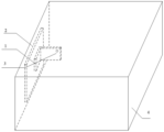
Fig. 3 is a schematic view of the heat sink of the present invention mounted on the side of the instrument housing.
In the figure: 1-inner heat conducting plate, 2-outer heat conducting plate, 3-round hole, 4-instrument box.
Detailed Description
In order that those skilled in the art will better understand the present invention, a more complete and complete description of the present invention is provided below in conjunction with the accompanying drawings and embodiments. In addition, the features of the embodiments and examples in the present application may be combined with each other without conflict.
A typical embodiment of the present invention provides a heat sink, as shown in fig. 1 and 2, comprising an inner heat conducting plate 1 and an outer heat conducting plate 2 respectively disposed at the inner and outer sides of an instrument box body to be heat-dissipated, wherein one or more inner heat conducting plates 1 and outer heat conducting plates 2 are fixedly connected; the inner heat conducting plate 1 is used for connecting a heat radiating element, and the outer heat conducting plate 2 is used for radiating heat to the outside of the instrument box body to be radiated.
According to the above embodiment, the inner heat conducting plate 1 is mounted with the high-power element or the circuit board with large heat productivity, the heat generated by the high-power element or the circuit board with large heat productivity is transferred to the outer heat conducting plate 2 through the inner heat conducting plate 1, and the heat on the outer heat conducting plate 2 is dissipated to the air, thereby achieving a good heat dissipation effect.
In a relatively specific embodiment, the section of the inner heat-conducting plate 1 is L-shaped, and has a first side and a second side which are perpendicular to each other, and the outer heat-conducting plate 2 is square; the first edge of the inner heat conducting plate 1 is fixedly connected with the middle part of the outer heat conducting plate 2. The inner heat conducting plate 1 and the outer heat conducting plate 2 can be fixed by adopting a spot welding method of a pulse welding machine, namely, the first edge of the inner heat conducting plate 1 and the outer heat conducting plate 2 are overlapped together and then are spot-welded into a whole by the pulse welding machine.
And a round hole 3 is formed in the second edge of the inner heat conducting plate 1, a screw is arranged in the round hole 3, and the screw is in threaded connection with a nut connected with a grounding wire. Outer heat-conducting plate 2 is installed in the outside of instrument box 4, operating personnel may touch outer heat-conducting plate 2, in order to prevent that the fin is electrified in the use of instrument, endanger personal safety, need link together interior heat-conducting plate 1 and earthing terminal through the wire, electrician's instrument all has dedicated earthing terminal, set up round hole 3 on heat-conducting plate 1 including, round hole 3 diameter is 6 millimeters, hexagonal screw M5x20 passes round hole 3 in the stainless steel, screw up stainless steel M5 nut intercommunication wire's one end and hexagonal screw M5x20 in the stainless steel together again, the wire other end is connected with the inside earthing terminal of instrument.
For good heat dissipation effect, the inner heat conducting plate 1 and the outer heat conducting plate 2 are both made of copper material. The thickness of the copper material of the inner heat conducting plate 1 is 1-3 mm, the thickness of the copper material of the outer heat conducting plate 2 is 2-5 mm, and the thickness of the copper material of the outer heat conducting plate 2 is slightly thicker than that of the copper material of the inner heat conducting plate 1 because the heat dissipation is mainly realized by the contact of the outer heat conducting plate 2 and air. Because the electrical instruments are various in types and the heat productivity in the instruments is different, the inner heat conducting plate 2 can be fixed on the outer heat conducting plate by adopting a plurality of pieces, namely more than two pieces, so as to further improve the heat dissipation effect.
Another exemplary embodiment of the present invention provides an outdoor electrical instrument, as shown in fig. 3, comprising an instrument case 4, and a heat sink according to the present invention disposed on the case. The instrument box body 4 is provided with a mounting hole for the inner heat conducting plate to pass through; the outer heat conducting plate 2 is fixedly connected with the outer surface of the instrument box body 4, and the inner heat conducting plate 1 penetrates through the mounting hole to enter the instrument box body 4 and is connected with a high-power element or a circuit board with large heat productivity in the instrument box body 4.
When installing the fin on instrument box 4, need open a hole in the side of instrument box 4, the size of hole, size are decided according to the area of contact of interior heat-conducting plate 1 with outer heat-conducting plate 2, open the hole after, pass the hole of opening to the interior heat-conducting plate 1 of fin, and the surface through epoxy AB glue bonding of outer heat-conducting plate 2 medial surface and instrument box 4 is fixed.
The scope of the utility model is not limited to the above embodiments, and various modifications and changes may be made by those skilled in the art, and any modifications, improvements and equivalents within the spirit and principle of the utility model should be included in the scope of the utility model.
Claims (7)
1. A heat sink, characterized by: the heat dissipation device comprises an inner heat conduction plate and an outer heat conduction plate which are respectively arranged at the inner side and the outer side of an instrument box body to be dissipated, wherein one or more inner heat conduction plates are fixedly connected with the outer heat conduction plate; the inner heat conducting plate is used for connecting a heat dissipation element, and the outer heat conducting plate is used for dissipating heat to the outside of the instrument box body to be dissipated.
2. The heat sink as recited in claim 1, wherein: the section of the inner heat conducting plate is L-shaped and is provided with a first side and a second side which are perpendicular to each other, and the outer heat conducting plate is square; the first edge of the inner heat conducting plate is fixedly connected with the middle part of the outer heat conducting plate.
3. The heat sink as recited in claim 2, wherein: and a round hole is formed in the second edge of the inner heat conducting plate, a screw is arranged in the round hole, and the screw is in threaded connection with a nut connected with a grounding wire.
4. A heat sink as claimed in claim 1, 2 or 3, wherein: the inner heat conducting plate and the outer heat conducting plate are both made of copper materials.
5. The heat sink as recited in claim 4, wherein: the thickness of the inner heat conducting plate is 1-3 mm, and the thickness of the outer heat conducting plate is 2-5 mm.
6. An outdoor electrician's instrument, includes the instrument box, its characterized in that: the heat sink of any one of claims 1 to 5 is further included in the case, and the case is provided with a mounting hole for the inner heat-conducting plate to pass through; the outer heat conducting plate is fixedly connected with the outer surface of the instrument box body, and the inner heat conducting plate penetrates through the mounting hole to enter the instrument box body and is connected with a high-power element or a circuit board with high heat productivity in the instrument box body.
7. An outdoor electrical instrument according to claim 6, wherein: the inner side surface of the outer heat conducting plate is fixedly connected with the outer surface of the instrument box body through epoxy resin AB glue.
Priority Applications (1)
| Application Number | Priority Date | Filing Date | Title |
|---|---|---|---|
| CN202122230038.6U CN215683098U (en) | 2021-09-15 | 2021-09-15 | Heat dissipation sheet and outdoor electrician instrument |
Applications Claiming Priority (1)
| Application Number | Priority Date | Filing Date | Title |
|---|---|---|---|
| CN202122230038.6U CN215683098U (en) | 2021-09-15 | 2021-09-15 | Heat dissipation sheet and outdoor electrician instrument |
Publications (1)
| Publication Number | Publication Date |
|---|---|
| CN215683098U true CN215683098U (en) | 2022-01-28 |
Family
ID=79963860
Family Applications (1)
| Application Number | Title | Priority Date | Filing Date |
|---|---|---|---|
| CN202122230038.6U Active CN215683098U (en) | 2021-09-15 | 2021-09-15 | Heat dissipation sheet and outdoor electrician instrument |
Country Status (1)
| Country | Link |
|---|---|
| CN (1) | CN215683098U (en) |
-
2021
- 2021-09-15 CN CN202122230038.6U patent/CN215683098U/en active Active
Similar Documents
| Publication | Publication Date | Title |
|---|---|---|
| EP4007149B1 (en) | Inverter | |
| US20240042952A1 (en) | Power conversion apparatus, connector-fixing structure and power-conversion-apparatus production method | |
| WO2023016253A1 (en) | Wiring base, electronic control box and air conditioner | |
| CN213880402U (en) | Heat radiation assembly of small laminated PCB | |
| CN208285207U (en) | A kind of shell for Switching Power Supply | |
| CN215683098U (en) | Heat dissipation sheet and outdoor electrician instrument | |
| CN212164093U (en) | Heat radiation shielding device | |
| CN114038686B (en) | Capacitor wiring device | |
| JP2010104146A (en) | Power converting apparatus | |
| CN211580514U (en) | Heat dissipation device and electronic equipment | |
| JP2012119401A (en) | Electrical equipment module having heat radiation structure | |
| JP2020048404A (en) | Electronic and electrical apparatus | |
| CN211481787U (en) | Servo transformer heat dissipation module | |
| CN210617874U (en) | Electronic equipment and heat radiation structure thereof | |
| CN108922873B (en) | A heat dissipation assembly and installation process for CQFP devices of spacecraft electronic products | |
| CN208353800U (en) | A kind of Switching Power Supply with insulation function | |
| CN219204956U (en) | Heat dissipation metal plate and antistatic surge structure | |
| CN217563958U (en) | Board card equipment and multi-board card device | |
| CN223515197U (en) | Electronic device | |
| CN224022086U (en) | Power supply chassis | |
| CN218548421U (en) | Radiator with electromagnetic shielding function | |
| CN224191826U (en) | Heat abstractor is arranged to power module busbar | |
| CN211655991U (en) | Frequency converter and mainboard thereof | |
| CN222281983U (en) | Inside heat radiation structure of IGBT module | |
| CN220383300U (en) | PCBA structure for improving efficiency of power circuit |
Legal Events
| Date | Code | Title | Description |
|---|---|---|---|
| GR01 | Patent grant | ||
| GR01 | Patent grant |