CN215744358U - Multi-angle adjustment bracket for atomizing nozzles in livestock and poultry houses - Google Patents
Multi-angle adjustment bracket for atomizing nozzles in livestock and poultry houses Download PDFInfo
- Publication number
- CN215744358U CN215744358U CN202121635738.7U CN202121635738U CN215744358U CN 215744358 U CN215744358 U CN 215744358U CN 202121635738 U CN202121635738 U CN 202121635738U CN 215744358 U CN215744358 U CN 215744358U
- Authority
- CN
- China
- Prior art keywords
- support
- rod
- sliding
- rotating
- snap ring
- Prior art date
- Legal status (The legal status is an assumption and is not a legal conclusion. Google has not performed a legal analysis and makes no representation as to the accuracy of the status listed.)
- Expired - Fee Related
Links
Images



Landscapes
- Catching Or Destruction (AREA)
Abstract
The utility model particularly relates to a multi-angle adjusting bracket for an atomization nozzle of a livestock and poultry house, which comprises a first bracket, a second bracket, a third bracket and a connecting block, wherein the second bracket is respectively and rotatably connected with the first bracket and the third bracket through the connecting block; the utility model can randomly adjust the spraying direction of the atomizing nozzle, adjust the height of the atomizing nozzle and adjust the rotation flexibility of the atomizing nozzle so as to be suitable for different working conditions.
Description
Technical Field
The utility model belongs to the technical field of livestock breeding equipment, and particularly relates to a multi-angle adjusting support for an atomization nozzle of a livestock house.
Background
When the poultry and livestock house is disinfected, atomizing nozzles are mostly adopted, some existing atomizing nozzles are mostly sprayed in a manual handheld mode, or the atomizing nozzles are fixed on a support and the support is moved for spraying, the spraying angle is flexible when the atomizing nozzles are sprayed in a handheld mode, and manual fatigue can be caused by long-time handheld operation, and a large amount of manpower is consumed; the spraying angle is limited when the spraying device is fixed on a bracket for spraying, and the disinfection and sterilization of the livestock house cannot be comprehensively realized. In order to solve the problems, the multi-angle adjusting bracket for the atomization nozzle of the livestock and poultry house is provided, and the spraying angle of the atomization nozzle can be adjusted at will.
In order to solve the problems, the multi-angle adjusting bracket for the atomization nozzle of the livestock and poultry house is provided, and the spraying angle of the atomization nozzle can be adjusted at will.
SUMMERY OF THE UTILITY MODEL
The utility model aims to overcome the defects in the prior art and provide a multi-angle adjusting bracket for an atomization nozzle of a livestock and poultry house.
The purpose of the utility model is realized as follows: support is adjusted to multi-angle for poultry house atomizer, including support one, support two, support three, the connecting block, support two respectively with support one, support three passes through the connecting block and rotates and be connected, still including the lifter, the pole setting, the connector, the sleeve, rotate the seat, the support, the lifter is rotatable to be connected with support three, the lifter top is connected with the connector, be connected for rotating between connector and the pole setting, be threaded connection between pole setting and the sleeve, the pole setting rotates with rotating the seat to be connected, the support is connected in rotating the seat side, rotate and be connected for rotating between seat and the support.
Further, still including rotating rod, top cap, snap ring, be threaded connection between rotating rod and the pole setting, the rotating rod upper end runs through and rotates seat and top cap, and the rotating rod middle part is the toper structure, and the snap ring is fixed in rotating the seat, and the snap ring lower part is cylindrical structure, and the bell mouth has been seted up to the snap ring inboard, and snap ring upper portion is the toper structure, and snap ring upper portion comprises a plurality of arc cards.
Further, the device comprises a rotating shaft, a locking cover, a stop lever, a limiting rod, an outer sliding sheet, an inner sliding sheet, a sliding block, a button, a first spring, a sliding rod, a stop ring, a clamping pin and an upper cover plate, wherein the side surface of the rotating seat is fixedly connected with the rotating shaft, the rotating shaft is rotatably provided with a support, the outer end of the rotating shaft is fixedly connected with the locking cover, the outer side surface of the locking cover is respectively provided with two symmetrical arc-shaped holes, one side of the outer side surface of each arc-shaped hole is uniformly provided with a plurality of clamping grooves, the sliding block is arranged in each arc-shaped hole in a sliding manner, the outer side surface of the sliding block is fixedly connected with the outer sliding sheet, the inner side surface of the sliding block is fixedly connected with the inner sliding sheet, the sliding rod is sequentially positioned in the outer sliding sheet, the sliding block and the inner sliding sheet in a sliding manner, the outer end of the sliding rod is fixedly connected with the button, the stop ring is sleeved on the outer side surface of the sliding rod and can move up and down, the first spring is arranged above the stop ring, the lower end of the lower sliding sheet is fixedly connected with the lower sliding sheet, the bayonet lock is fixed on the outer side surface of the sliding rod, and one outer end of the spring is fixedly connected with the bayonet lock; the bayonet lock slidable with outer gleitbretter, slider sliding connection, bayonet lock and draw-in groove are clearance fit, and the pin is fixed at the support right-hand member face, and the pin is located between two gag lever posts.
Further, the fixed slot has been seted up including the support upper surface still, and the fixed slot left side gliding is provided with the elevator from top to bottom, and elevator lower extreme fixedly connected with spring two, terminal surface fixedly connected with pull rod before the elevator, the pull rod gliding is located the support from top to bottom, and the pull rod front end runs through the support, and the upper cover plate right-hand member is rotatable to be connected with the support, and the locked groove has been seted up to the other one end of upper cover plate, is clearance fit between locked groove inside and the lifter plate.
When the device is used, the atomizing nozzle is detachably placed on the device, namely the atomizing nozzle is placed in the fixed groove, the upper cover plate is rotated around the connecting shaft, so that the upper cover plate is clamped with the support, namely the pull rod is pulled downwards, the upper cover plate is attached to the left side of the support, the pull rod is loosened, and the lifting block moves upwards under the action of the elasticity of the spring; the lifting block is clamped in a locking groove in the upper cover plate, and the lifting block is in clearance fit with the locking groove; because the apron is the arc and removes, consequently the upper cover plate can't remove when the elevator is located the locked groove, accomplishes the fixed to atomizer.
Through expansion support one, support two, support three extend, and then drive shower nozzle mechanism and remove, can increase atomizer's horizontal migration scope, be provided with the lifter and can drive atomizer and reciprocate, increase atomizer reciprocating range, but the support rotates relatively and rotates the seat for the pole setting for rotating the seat, can realize the omnidirectional rotation of atomizer, and atomizer can spout to any angle.
The upright rod is rotatably connected with the lifting rod, and when the upright rod and the lifting rod need to be fixed, the sleeve can be rotated from the upright rod, so that the connector and the upright rod are sleeved in the sleeve, and the connection and the fixation of the connector and the upright rod are completed; the connector is rotationally connected with the upright stanchion, and when the sleeve is positioned on the upright stanchion, the upright stanchion is rotated, so that the rotation of the rotating seat can be realized; the vertical rod which is rotatable relative to the connector is arranged, so that the horizontal moving distance above the sprayer mechanism can be increased, and the sprayer mechanism can be sprayed and sprayed by crossing the colony house from the upper side.
Be provided with the rotary rod, the top cap, the snap ring can change the rotary rod for the height of pole setting through rotating the rotary rod, because the rotary rod middle part is the toper structure, the snap ring is fixed in rotating the seat, the snap ring lower part is cylindrical structure, the bell mouth has been seted up to the snap ring inboard, snap ring upper portion is the toper structure, snap ring upper portion comprises a plurality of arc cards, rotary rod middle part and snap ring laminating chucking gradually when rotary rod rebound, the arc card pressurized of snap ring top is opened, the rotary rod makes progress more tightly of card between snap ring and the rotary rod more, and then make to rotate the seat and rotate more difficult when rotating for the pole setting, realize rotating the regulation of pivoted flexibility ratio between seat and the pole setting. If the rotating seat and the upright rod rotate, the atomizing nozzle is easy to rotate quickly when working and is inconvenient to operate once a flexible person leaves the hand.
The device is provided with a rotating shaft, a locking cover, a stop lever, a limiting rod, an outer slip sheet, an inner slip sheet, a sliding block, a button, a first spring, a sliding rod, a stop ring, a bayonet lock and an upper cover plate, wherein the rotating range of the stop lever can be limited by two limiting rods, namely the button is pulled outwards, the sliding rod drives the bayonet lock to move upwards, the sliding block is pushed to move along an arc-shaped hole, when the sliding block moves to a proper position and the button is loosened, the sliding rod moves inwards under the action of the pulling force of the spring, the bayonet lock is clamped into a clamping groove on the outer side of the arc-shaped hole, the limiting rod is fixed at the moment, the stop lever is blocked by the two limiting rods when rotating, so that the rotating range is limited, a support can be controlled to rotate around the rotating shaft within a certain range, and then the atomizing nozzle is limited to rotate within a certain range, the atomizing nozzle is prevented from being sprayed to other ranges, or the atomizing nozzle is prevented from rotating by any angle when a person suddenly does not hold up the nozzle mechanism, causing potential safety hazards.
The spraying direction of atomizer can be adjusted at will to this device to adjustable atomizer's height, and can adjust atomizer's rotation flexibility ratio, so that be suitable for different working conditions.
Drawings
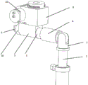
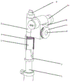
Fig. 1 is a schematic structural diagram of the utility model.
Fig. 2 is a schematic structural view of the utility model when the vertical rod and the lifting rod are folded.
Fig. 3 is a cross-sectional view of the middle sleeve of the utility model.
Fig. 4 is a partial structural sectional view of the utility model.
Fig. 5 is a partial structure sectional view of the rotating base of the utility model.
Fig. 6 is a partial structural sectional view of the support of the utility model.
Fig. 7 is a partial structure sectional view of the locking cover of the utility model.
Figure 8 is utility model's outer gleitbretter, interior gleitbretter, slider structure cross-sectional view.
Fig. 9 is a schematic structural view of the upper cover plate of the utility model.
Description of reference numerals:
1. the spray nozzle comprises a lifting rod, 2. a connector, 3. an upright rod, 4. a sleeve, 5. a rotating seat, 6. a rotating rod, 7. a locking cover, 8. a support, 9. a rotating shaft, 10. a top cover, 11. a support III, 12. a support II, 13. a support I, 14. a connecting block, 15. a snap ring, 16. a retaining ring, 17. a pull rod, 18. an upper cover plate, 19. the lifting block, 20. a spring II, 21. an outer sliding sheet, 22. a limiting rod, 23. a button, 24. an inner sliding sheet, 25. a sliding block, 26. a retaining rod, 27. a sliding rod, 28. a bayonet lock, 29. a spring I, 30. a locking groove, 31. a connecting shaft, 32. the spray nozzle.
Detailed Description
Example 1
As shown in fig. 1-9, the object of the utility model is achieved by: a multi-angle adjusting bracket for an atomization nozzle of a livestock and poultry house comprises a bracket I13, a bracket II 12, a bracket III 11, a connecting block 14, a lifting rod 1, a vertical rod 3, a connector 2, a sleeve 4, a rotating seat 5, a rotating rod 6, a rotating shaft 9, a top cover 10, a snap ring 15, a locking cover 7, a stop lever 26, a limiting rod 22, a support 8, an outer sliding sheet 21, an inner sliding sheet 24, a sliding block 25, a button 23, a spring I29, a sliding rod 27, a stop ring 16, a bayonet pin 28, a spring II 20, a pull rod 17, a lifting block 19 and an upper cover plate 18, wherein the bracket I13 is rotatably connected with a carrier vehicle, the bracket II 12 is respectively rotatably connected with the bracket I13 and the bracket III 11 through the connecting block 14, the bracket I13, the bracket II 12 and the bracket III 11 are mutually unfolded to increase the transverse moving range of the nozzle mechanism, the lifting rod 1 is rotatably connected with the bracket III 11, the top end of the lifting rod 1 is connected with the connector 2, for rotating between connector 2 and the pole setting 3 and being connected, 2 lower parts of connector are the ladder cylinder, and the ladder cylinder can guarantee sleeve 4 bottom and 2 lower part contacts of connector when sleeve 4 falls, plays the effect that prevents the gliding to sleeve 4, and upper portion is the arc structure, combines the figure to learn this kind of arc structure and connected mode, can be so that keep vertically relation of connection between connector 2 and the pole setting 3. The upright rod 3 is in threaded connection with the sleeve 4, the upright rod 3 is of a circular structure, the diameters of the upright rod 3 and the upper part of the connector 2 are the same, and the sleeve 4 is convenient for connecting and clamping the upright rod 3 and the upper part of the connector 2; 3 upper ends of pole setting are rotated with rotation seat 5 and are connected, rotate 5 upper ends of seat and be connected with top cap 10 rotation, be threaded connection between rotary rod 6 and the pole setting 3, 6 upper ends of rotary rod run through and rotate seat 5 and top cap 10, 6 middle parts of rotary rod are the toper structure, snap ring 15 is fixed in rotating seat 5, 15 lower parts of snap ring are cylindrical structure, the bell mouth has been seted up to 15 inboards of snap ring, 15 upper portions of snap ring are the toper structure, 15 upper portions of snap ring comprise a plurality of arc cards, the elasticity to 6 middle parts of rotary rod can be realized to the arc card, and then the flexibility ratio when the restriction rotates seat 5 rotations.
A rotating shaft 9 is fixedly connected to the side surface of the rotating seat 5, a support 8 is rotatably arranged on the rotating shaft 9, a locking cover 7 is fixedly connected to the outer end of the rotating shaft 9, two symmetrical arc-shaped holes are respectively arranged on the outer side surface of the locking cover 7, a plurality of clamping grooves are uniformly arranged on one side of the outer side surface of each arc-shaped hole, a sliding block 25 is slidably arranged in each arc-shaped hole, the outer side surface of each sliding block 25 is fixedly connected with an outer sliding sheet 21, the inner side surface of each sliding block 25 is fixedly connected with an inner sliding sheet 24, a limiting rod 22 is fixedly arranged on the inner side of each inner sliding sheet 24, a sliding rod 27 is slidably arranged on each outer sliding sheet 21 and each sliding block 25 in sequence, in the inner sliding piece 24, the outer end of the sliding rod 27 is fixedly connected with a button 23, the outer side surface of the sliding rod 27 is sleeved with a baffle ring 16 which can move up and down, a first spring 29 is arranged above the baffle ring 16, the lower end of the baffle ring 16 is fixedly connected with the lower sliding piece, a clamping pin 28 is fixed on the outer side surface of the sliding rod 27, and the outer end of the first spring 29 is fixedly connected with the clamping pin 28; the bayonet 28 can slide and is connected with the outer sliding sheet 21 and the sliding block 25 in a sliding way, and the bayonet 28 is in clearance fit with the bayonet; the stop lever 26 is fixed on the right end surface of the support 8, and the stop lever 26 is positioned between the two limiting rods 22; the fixed slot has been seted up to 8 upper surfaces of support, gliding about the fixed slot left side is provided with elevator 19, two 20 of 19 lower extreme fixedly connected with springs of elevator, terminal surface fixedly connected with pull rod 17 before the elevator 19, the gliding about being located in support 8 of pull rod 17, pull rod 17 front end runs through support 8, the rotatable and support 8 of upper cover plate 18 right-hand member is connected, locked groove 30 has been seted up to 18 other one end of upper cover plate, be clearance fit between the inside and the lifter plate of locked groove 30, can realize the chucking of lifter plate to upper cover plate 18. The bracket mechanism can adjust the angle and the height of spraying the subacid electrolyzed water, improve the flexibility of spraying, increase the spraying area and improve the disinfection efficiency.
The atomizing nozzle 32 can be held by hand, or the atomizing nozzle 32 can be fixed in a groove, and then the upper cover plate 18 rotates around the connecting shaft 31, so that the upper cover plate 18 is clamped with the support 8, namely after the pull rod 17 is pulled downwards, the upper cover plate 18 is attached to the left side of the support 8, the pull rod 17 is loosened, and the lifting block 19 moves upwards under the elastic force of the spring; the lifting block 19 is clamped in the locking groove 30 in the upper cover plate 18, and the lifting block 19 is in clearance fit with the locking groove 30; because the cover plate moves in an arc shape, the upper cover plate 18 cannot move when the lifting block 19 is positioned in the locking groove 30, and the fixing of the spray head mechanism is completed.
Through unfolding first support 13, second support 12, third support 11 extends, and then drive atomizer 32 and remove, can increase atomizer 32's horizontal migration scope, it can drive the shower nozzle mechanism and reciprocate to be provided with lifter 1, increases atomizer 32 vertical migration scope, but support 8 rotates relatively and rotates seat 5 for rotating seat 5 and rotate for pole setting 3, can realize the omnidirectional rotation of atomizer 32, atomizer 32 can spout to any angle.
The upright rod 3 is rotatably connected with the lifting rod 1, and when the upright rod 3 and the lifting rod 1 need to be fixed, the sleeve 4 can be rotated off the upright rod 3, so that the connector 2 and the upright rod 3 are sleeved in the sleeve 4, and the connection and the fixation of the connector 2 and the upright rod 3 are completed; the connector 2 is rotatably connected with the upright rod 3, and when the sleeve 4 is positioned on the upright rod 3, the upright rod 3 is rotated to realize the rotation of the rotating seat 5; the arrangement of the upright 3 which is rotatable relative to the connecting head 2 increases the horizontal movement distance above the atomizer head 32, and the atomizer head can be sprayed by passing over a colony house from above.
Be provided with rotary rod 6, top cap 10, snap ring 15 can change the height of rotary rod 6 for pole setting 3 through rotating rotary rod 6, because rotary rod 6 middle part is the toper structure, snap ring 15 is fixed in rotating seat 5, the 15 lower parts of snap ring are cylindrical structure, the bell mouth has been seted up to snap ring 15 inboard, 15 upper portions of snap ring are the toper structure, 15 upper portions of snap ring comprise a plurality of arc cards, 6 middle parts of rotary rod are laminated gradually chucking with snap ring 15 when rotary rod 6 rebound, the arc card pressurized of snap ring 15 top is opened, the rotary rod 6 is more tight more of card between upwards snap ring 15 and the rotary rod 6, and then make to rotate seat 5 and rotate the time more difficult for pole setting 3, realize rotating the pivoted flexibility ratio between seat 5 and the pole setting 3. If the rotating seat 5 and the upright rod 3 rotate too flexibly, once a person leaves the hand, the spray head mechanism is easy to rotate quickly when working, and is inconvenient to operate.
The device is provided with a rotating shaft 9, a locking cover 7, a stop lever 26, limiting rods 22, an outer sliding sheet 21, an inner sliding sheet 24, a sliding block 25, a button 23, a spring I29, a sliding rod 27, a stop ring 16, a clamping pin 28 and an upper cover plate 18, wherein the rotating range of the stop lever 26 can be limited by the two limiting rods 22, namely the button 23 is pulled outwards, the sliding rod 27 drives the clamping pin 28 to move upwards, the sliding block 25 is pushed to move along an arc-shaped hole, when the button 23 is moved to a proper position, the sliding rod 27 moves inwards under the action of the spring pull force, the clamping pin 28 is clamped in a clamping groove on the outer side of the arc-shaped hole, the limiting rod 22 is fixed at the moment, the stop lever 26 is blocked by the two limiting rods 22 during rotation, so that the rotating range is limited, the support 8 can be controlled to rotate around the rotating shaft 9 within a certain range, further the atomizing nozzle 32 is limited to rotate within a certain range, and the atomizing nozzle 32 is prevented from being sprayed to other ranges during spraying, or when a person suddenly does not hold the atomizing nozzle 32, the nozzle mechanism is prevented from rotating at any angle, so that potential safety hazards are caused.
In the description of the present invention, it is to be understood that the terms "center", "longitudinal", "lateral", "length", "width", "thickness", "upper", "lower", "front", "rear", "left", "right", "vertical", "horizontal", "top", "bottom", "inner", "outer", "clockwise", "counterclockwise", and the like, indicate orientations and positional relationships based on those shown in the drawings, and are used only for convenience of description and simplicity of description, and do not indicate or imply that the equipment or element being referred to must have a particular orientation, be constructed and operated in a particular orientation, and thus, should not be considered as limiting the present invention.
The above description is only for the purpose of illustrating the preferred embodiments of the present invention and is not to be construed as limiting the present invention, and it will be understood by those skilled in the art that various changes and modifications may be made therein without departing from the spirit and scope of the utility model.
Claims (4)
1. Support is adjusted to multi-angle for poultry house atomizer, including support one, support two, support three, connecting block, support two crosses the connecting block with support one, support three respectively and rotates and be connected its characterized in that: still including lifter, pole setting, connector, sleeve, rotation seat, support, the rotatable and support three of lifter are connected, and the lifter top is connected with the connector, is connected for rotating between connector and the pole setting, is threaded connection between pole setting and the sleeve, and the pole setting rotates with rotating the seat and is connected, and the support is connected in rotating the seat side, rotates and is connected for rotating between seat and the support.
2. The multi-angle adjusting bracket for the atomizer of livestock and poultry house as claimed in claim 1, wherein: still including rotary rod, top cap, snap ring, be threaded connection between rotary rod and the pole setting, the rotary rod upper end runs through and rotates seat and top cap, and the rotary rod middle part is the toper structure, and the snap ring is fixed in rotating the seat, and the snap ring lower part is cylindrical structure, and the bell mouth has been seted up to the snap ring inboard, and snap ring upper portion is the toper structure, and snap ring upper portion comprises a plurality of arc cards.
3. The multi-angle adjusting bracket for the atomizer of livestock and poultry house according to claim 1 or 2, wherein: the sliding block is fixedly connected with the inner sliding sheet, the limiting rod is fixedly arranged on the inner side of the inner sliding sheet, the sliding rod is slidably positioned in the outer sliding sheet, the sliding block and the inner sliding sheet in sequence, the button is fixedly connected with the outer end of the sliding rod, the baffle ring is sleeved on the outer side surface of the sliding rod in a vertically movable manner, a first spring is arranged above the baffle ring, and the lower end of the baffle ring is fixedly connected with the lower sliding sheet, the bayonet lock is fixed on the outer side surface of the sliding rod, and one outer end of the spring is fixedly connected with the bayonet lock; the bayonet lock slidable with outer gleitbretter, slider sliding connection, bayonet lock and draw-in groove are clearance fit, and the pin is fixed at the support right-hand member face, and the pin is located between two gag lever posts.
4. The multi-angle adjusting bracket for the atomizer of the livestock and poultry house as claimed in claim 3, wherein: the fixed slot has still been seted up including the support upper surface, and the fixed slot left side gliding is provided with the elevator from top to bottom, and elevator lower extreme fixedly connected with spring two, terminal surface fixedly connected with pull rod before the elevator, the pull rod gliding is located the support from top to bottom, and the pull rod front end runs through the support, and the upper cover plate right-hand member is rotatable to be connected with the support, and the locked groove has been seted up to the other one end of upper cover plate, is clearance fit between inside and the lifter plate of locked groove.
Priority Applications (1)
| Application Number | Priority Date | Filing Date | Title |
|---|---|---|---|
| CN202121635738.7U CN215744358U (en) | 2021-07-19 | 2021-07-19 | Multi-angle adjustment bracket for atomizing nozzles in livestock and poultry houses |
Applications Claiming Priority (1)
| Application Number | Priority Date | Filing Date | Title |
|---|---|---|---|
| CN202121635738.7U CN215744358U (en) | 2021-07-19 | 2021-07-19 | Multi-angle adjustment bracket for atomizing nozzles in livestock and poultry houses |
Publications (1)
| Publication Number | Publication Date |
|---|---|
| CN215744358U true CN215744358U (en) | 2022-02-08 |
Family
ID=80105913
Family Applications (1)
| Application Number | Title | Priority Date | Filing Date |
|---|---|---|---|
| CN202121635738.7U Expired - Fee Related CN215744358U (en) | 2021-07-19 | 2021-07-19 | Multi-angle adjustment bracket for atomizing nozzles in livestock and poultry houses |
Country Status (1)
| Country | Link |
|---|---|
| CN (1) | CN215744358U (en) |
-
2021
- 2021-07-19 CN CN202121635738.7U patent/CN215744358U/en not_active Expired - Fee Related
Similar Documents
| Publication | Publication Date | Title |
|---|---|---|
| PL94847B1 (en) | BATH SHOWER | |
| EP2609827A1 (en) | Parasol with cooling device | |
| CN208403573U (en) | A kind of brush of angle adjustable | |
| CN208049049U (en) | A kind of disinfecting spray head | |
| CN204362797U (en) | A kind of gardens sprayer unit | |
| CN210352851U (en) | Navel orange is planted with medicine spraying apparatus of adjustable height | |
| CN110463619B (en) | Quick cleaning and removing device for animal fur parasites | |
| CN211080926U (en) | Water based paint spraying device for building | |
| CN218540866U (en) | Water tap capable of arbitrarily adjusting water outlet angle | |
| CN214856255U (en) | Adjustable shower head with side shower head | |
| CN217564439U (en) | Irrigation device for hydraulic engineering | |
| CN215929995U (en) | Interior decoration environmental protection removes formaldehyde device | |
| CN223232572U (en) | Multi-angle controllable baking tray structure | |
| CN109393717A (en) | A kind of test tube brush | |
| CN206403716U (en) | It is new from tweaking type mop | |
| CN210234387U (en) | Barbell inkjet printer | |
| CN211244754U (en) | Sterilizing and epidemic-preventing spraying device for farm | |
| CN218869186U (en) | Double-head rotary sprayer capable of adjusting spraying radius | |
| CN206866454U (en) | A kind of hand-held multipurpose spraying device | |
| CN224070853U (en) | Animal doctor uses atomizing deodorizing device | |
| CN207520533U (en) | Novel recreational body-building integration fitness equipment | |
| CN214864483U (en) | A multifunctional shower for a bath | |
| CN220967757U (en) | Negative ion sprayer | |
| CN216601399U (en) | Aviation electrostatic spraying and electrostatic nozzle device for aviation pesticide spraying | |
| CN210960793U (en) | Electronic spraying device |
Legal Events
| Date | Code | Title | Description |
|---|---|---|---|
| GR01 | Patent grant | ||
| GR01 | Patent grant | ||
| CF01 | Termination of patent right due to non-payment of annual fee | ||
| CF01 | Termination of patent right due to non-payment of annual fee |
Granted publication date: 20220208 |