SUMMERY OF THE UTILITY MODEL
The utility model aims to provide an assembled outer wall system and an assembling mechanism thereof, wherein the assembling mechanism is used for fixing an outer decorative plate and an outer wall body, and can improve the safety, reliability and durability of the assembly of the outer decorative plate on the basis of realizing the assembly operation of the outer wall system.
In order to solve the above technical problems, the present invention provides an assembly mechanism for an assembled exterior wall system, comprising a fixing unit for fixedly connecting with an exterior wall, a transition connecting member and a cantilever member; the inner end of the transition connecting piece is fixedly connected with the fixing unit, the outer end of the transition connecting piece is fixedly connected with the middle part of the cantilever piece, and the cantilever piece extends along the horizontal direction and is parallel to the outer wall body; two ends of the cantilever part are respectively provided with an upper connecting position and a lower connecting position, the upper connecting position is used for being connected with the lower end of the outer decorative plate, and the lower connecting position is used for being connected with the upper end of the outer decorative plate.
The utility model provides an assembly mechanism for assembling an exterior wall system, in particular to an installation between an exterior decorative plate and an exterior wall body, wherein a fixing unit is fixedly connected with the exterior wall body, the inner end and the outer end of a transition connecting piece are respectively fixedly connected with the fixing unit and the middle part of a cantilever piece, and both end parts of the cantilever piece are respectively provided with an upper connecting position and a lower connecting position for connecting with the exterior decorative plate.
Optionally, an outer connecting piece is fixedly connected to an end of the cantilever piece, the outer connecting piece is a T-shaped connecting piece, the T-shaped connecting piece includes a first plate and a second plate, and the first plate is vertically and fixedly connected to the middle of the second plate; the first plate is connected with the end of the cantilever part and is perpendicular to the outer wall body, the second plate extends along the vertical direction, the upper end of the second plate forms the upper connecting position, and the lower end of the second plate forms the lower connecting position.
Optionally, the first plate has a jackscrew hole, a jackscrew is screwed in the jackscrew hole, and the jackscrew passes through the jackscrew hole and can abut against the cantilever part.
Optionally, an outer connecting piece is fixedly connected to an end of the cantilever piece, and the outer connecting piece includes an upper L-shaped connecting piece and a lower L-shaped connecting piece; the first plate part of the upper L-shaped connecting piece is connected with the end part of the cantilever piece and is arranged perpendicular to the outer wall body, and the second plate part of the upper L-shaped connecting piece extends along the vertical direction to form the upper connecting position; and the first plate part of the lower L-shaped connecting piece is connected with the end part of the cantilever piece and is perpendicular to the outer wall body, and the second plate part of the lower L-shaped connecting piece extends along the vertical direction to form the lower connecting position.
Optionally, the first plate portion of the upper L-shaped connecting piece and the first plate portion of the lower L-shaped connecting piece are fixedly connected to the cantilever piece through a fastening assembly; go up the second board portion of L type connecting piece certainly the outer end of going up the first board portion of L type connecting piece upwards extends, the second board portion of L type connecting piece certainly down the outer end downwardly extending of the first board portion of L type connecting piece.
Optionally, the cantilever part includes a vertical plate body parallel to the vertical direction, and the end of the vertical plate body forms the upper connection position; the end part of the cantilever part is fixedly connected with an outer connecting piece which is an L-shaped piece, a first plate of the L-shaped piece is fixedly connected with the end part of the cantilever part, a second plate of the L-shaped piece vertically extends downwards from the joint of the second plate and the first plate, and the second plate forms the lower connecting position.
Optionally, the cantilever further includes a horizontal plate parallel to the horizontal direction, the vertical plate is fixedly connected to the outer edge of the horizontal plate, and the first plate of the L-shaped member is fixedly connected to the horizontal plate through a fastening unit.
Optionally, an end of the cantilever part has a first connection hole for connecting with the external connection part, and the external connection part has a second connection hole for connecting with the cantilever part;
one of the first connecting hole and the second connecting hole is a long round hole, and the axis of the long round hole extends along the horizontal direction and is parallel to or vertical to the outer wall body; or the first connecting hole and the second connecting hole are both long round holes, the axes of the two long round holes are perpendicular to each other, and the axis of one of the long round holes is perpendicular to the outer wall body.
Optionally, the transition piece includes vertical keel and supporter, vertical keel extends along vertical direction, vertical keel with fixed unit rigid coupling just presses close to the wall body sets up, the supporter perpendicular to the wall body sets up, the inner of supporter with vertical keel rigid coupling, the outer end of supporter with cantilever member's middle part rigid coupling.
Optionally, the vertical keel is in the form of an angle steel, and/or the support is in the form of an angle steel, a square steel pipe or a steel plate.
Optionally, the transition connecting member includes a supporting member, the supporting member includes a first supporting plate parallel to the outer wall and a second supporting plate perpendicular to the outer wall, the first supporting plate is fixedly connected to the fixing unit, an inner end of the second supporting plate is fixedly connected to the first supporting plate, and an outer end of the second supporting plate is fixedly connected to a middle portion of the cantilever member.
Optionally, the support member is a T-shaped structure, and the second support plate is fixedly connected to the middle position of the first support plate; the first supporting plate and the fixing unit are provided with two fixing points which are respectively positioned at two sides of the second supporting plate.
Optionally, the support member comprises two L-shaped support members, each L-shaped support member comprising a first support plate and a second support plate, the second support plates of the two L-shaped support members abutting.
Optionally, the transition connecting piece includes adaptor and perpendicular fossil fragments, the adaptor with the fixed unit rigid coupling, the adaptor includes the perpendicular to the switching board portion of the outer wall body, perpendicular fossil fragments extend and rigid coupling in along vertical direction the outer end of switching board portion.
Optionally, the vertical keel comprises two opposite wall plates, and the plate surfaces of the wall plates are perpendicular to the outer wall body; the adapter comprises two adapter plates which are respectively positioned at the outer sides of the two wallboards of the vertical keel, and the vertical keel is fixedly connected with the adapter through a fastening part penetrating through the adapter plates and the wallboards.
Optionally, the vertical keel is in a square steel tube form or a channel steel form, and/or the adaptor comprises two L-shaped corner connectors, one side of each L-shaped corner connector is fixedly connected with the fixing unit, and the other side of each L-shaped corner connector is in a switching plate part form, or the adaptor comprises a substrate and two parallel vertical plates fixedly connected to the substrate, the substrate is fixedly connected with the fixing unit, and the vertical plates form the switching plate part.
Optionally, a heat insulation gasket is arranged between the inner end of the transition connecting piece and the outer wall body.
Optionally, the fixing unit includes an anchor bolt, or the fixing unit includes a fixing member, the fixing member includes a groove-shaped portion, the groove-shaped portion includes a groove bottom wall and two groove side walls, the two groove side walls are oppositely disposed, an open groove facing outward is defined by the groove bottom wall and the two groove side walls, the end portion of the groove side wall is further provided with a bending portion, the bending directions of the two bending portions are opposite, and the transition connecting member is fixedly connected with the fixing member through a T-shaped bolt inversely placed in the open groove; the fixed part also comprises at least two anchoring columns fixedly connected with the bottom wall of the groove, and the fixed part is fixedly inserted into the outer wall body through the anchoring columns.
Optionally, the upper connecting position includes a plate structure extending vertically and parallel to the outer wall body; the assembly mechanism further comprises a hanging piece fixedly connected to the lower end of the outer decorative plate, the hanging piece comprises a fixed connecting piece fixedly attached to the outer decorative plate and a hanging piece fixedly connected to the fixed connecting piece, the hanging piece is parallel to the fixed connecting piece, a preset distance is formed between the fixed connecting piece and the hanging piece, so that the hanging piece is fixed to the outer decorative plate, a hanging groove with a downward opening is formed between the hanging piece and the outer decorative plate, and the plate structure of the upper connecting position can be inserted into the hanging groove.
Optionally, the lower connection position includes vertical extension and the parallel plate structure of wall body, the plate structure is in through the rigid coupling back of the body bolt and fixation nut of outer plaque upper end with outer plaque rigid coupling, the plate structure has the confession back of the body bolt male rectangular hole, the vertical extension is followed to the axis direction in rectangular hole.
The utility model also provides an assembled exterior wall system, which comprises an exterior wall body, a heat insulation layer and an exterior wall, wherein the heat insulation layer is arranged between the exterior wall body and the exterior wall, and the exterior wall comprises a plurality of exterior plates; the outer wall body is fixedly connected with the outer decorative plate through the assembling mechanism.
Since the above-mentioned assembling mechanism has the above-mentioned technical effects, the assembled exterior wall system including the assembling mechanism also has the same technical effects, and the discussion thereof is not repeated here.
Detailed Description
The assembling mechanism provided by the utility model is used for an assembled external wall system, and is particularly used for fixedly connecting an external decorative plate and an external wall body in the assembled external wall system.
The assembled exterior wall system provided by the utility model comprises an exterior wall body, an insulating layer and an exterior wall, wherein the insulating layer is arranged between the exterior wall body and the exterior wall, the exterior wall comprises a plurality of exterior plates which are specifically formed by splicing the exterior plates, the insulating layer comprises a plurality of insulating blocks, and the insulating blocks and the exterior plates are prefabricated parts, namely the prefabricated parts are manufactured in a processing factory in advance.
The outer wall body can be integrally in a concrete structure form, and can also be in a mixed structure of a concrete structure and a secondary filling wall.
According to the utility model, the assembling mechanism comprises a fixing unit fixedly connected with the outer wall body, a transition connecting piece and a cantilever piece, wherein the inner end of the transition connecting piece is fixedly connected with the fixing unit, the outer end of the transition connecting piece is fixedly connected with the middle part of the cantilever piece, the cantilever piece extends along the horizontal direction and is parallel to the outer wall body, an upper connecting position and a lower connecting position are respectively arranged at two end parts of the cantilever piece, the upper connecting position is used for being connected with the lower end of the outer decorative plate, and the lower connecting position is used for being connected with the upper end of the outer decorative plate.
During practical application, the fixed unit can be pre-buried at outer wall body in advance, according to typesetting the requirement ligature on concrete structure's reinforcing bar before pouring formation outer wall body promptly, and after the outer wall body was formed in follow-up pouring, fixed unit and outer wall body were fixed, and the steadiness is good, and of course, the fixed unit also can be after outer wall body shaping, through modes such as anchor solid insertion in outer wall body.
In practical application, after the outer wall body is formed, the heat-insulating layer is fixedly connected with the outer wall body in an anchoring mode or a mode of combining bonding and anchoring according to the assembling condition of the outer wall body and the assembling mechanism and the practical application requirements.
The fixed connection between the external decorative plate and the external wall body can be realized through the assembling mechanism, the stress of the external decorative plate is directly transmitted to the external wall body through the assembling mechanism, and the safety, the reliability and the use durability of the assembly of the external decorative plate can be improved through independent stress.
In order that those skilled in the art will better understand the disclosure, the utility model will be described in further detail with reference to the accompanying drawings and specific embodiments.
For ease of understanding and simplicity of description, the following description will be made in conjunction with the assembled exterior wall system and the assembling mechanism thereof, and since the assembled exterior wall system has the same basic structure and is different from the assembling mechanism, the assembling mechanism will be described in the following embodiments.
The term "inner" as used herein refers to the side of the exterior wall that is adjacent to the exterior wall, as opposed to the side of the exterior wall that is remote from the exterior wall, i.e., the side adjacent to the exterior trim panel, as referred to herein as "outer".
Example one
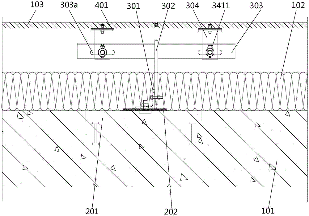
Referring to fig. 1 and 2, fig. 1 is a top view, partially cross-sectional view of an assembled exterior wall system according to a first embodiment of the present invention; fig. 2 is a side elevation, partially cut-away view of a first embodiment of the assembled exterior wall system provided by the present invention.
In this embodiment, the fixing unit of the assembling mechanism of the assembled exterior wall system includes a fixing member 201, the fixing member 201 includes a groove-shaped portion 211 and an anchoring column 212, the groove-shaped portion 211 includes a groove bottom wall and two groove side walls, the two groove side walls are oppositely disposed, the groove bottom wall and the two groove side walls enclose an open groove, during assembly, the open groove of the groove-shaped portion 211 faces outward, i.e., in a direction of the exterior trim 103, the anchoring column 212 is fixedly connected to the groove bottom wall, and the fixing member 201 is anchored on the exterior wall 101 through the anchoring column 212, or is pre-embedded in the exterior wall 101 in advance. The two groove side walls of the groove-shaped portion 211 are further provided with bending portions, and the two bending portions are arranged oppositely, so that the size of the opening of the open groove is smaller than that of the groove cavity. To ensure the stability between the fixing member 201 and the outer wall 101, more than two anchoring columns 212 are preferably provided on one fixing member 201.
The transition connection piece of the assembly mechanism comprises a vertical keel 301 and a support piece 302, in this embodiment, as shown in fig. 1, the vertical keel 301 is in an angle steel form, one side of the vertical keel 301 is fixedly connected with the fixing piece 201 through a T-shaped bolt inverted at a groove-shaped part 211 of the fixing piece 201, the head of the T-shaped bolt is located in a groove cavity of the groove-shaped part 211, due to the structural arrangement of a bending part of the side wall of the groove, interference can be formed between the head of the T-shaped bolt, the T-shaped bolt is prevented from being separated from the fixing piece 201, and after the rod part of the T-shaped bolt penetrates through one side of the vertical keel 301, the vertical keel 301 can be fixed through a nut screwed with the T-shaped bolt.
In actual installation, according to the design requirement of the external wall system, the heat insulation gasket 202 can be arranged between the vertical keel 301 and the external wall 101, and specifically, the T-shaped bolt firstly penetrates through the heat insulation gasket 202 and then penetrates through one side of the vertical keel 301, so as to meet the requirement of a heat bridge.
The supporting member 302 is fixedly connected to the other side of the vertical keel 301, it can be understood that one side of the vertical keel 301 connected to the fixing member 201 is parallel to the outer wall 101, and the other side of the vertical keel 301 connected to the supporting member 302 is perpendicular to the outer wall 101.
As shown in fig. 2, the connecting holes of the mullion 301 and the supporting member 302 may be provided as vertically extending oblong holes to adjust the height of the supporting member 302, and thus the height of the connecting position of the two ends of the subsequent cantilever member 303, and the oblong holes may be formed on the mullion 301 or on the supporting member 302, and there are at least two connecting points between the two members in order to ensure the stability of the connection between the supporting member 302 and the mullion 301.
As shown in fig. 1 and 2, in this embodiment, the cantilever member 303 is in the form of an angle steel, and the outer end of the cantilever member 303 and the supporting member 302 can be fixed by welding or by providing an adapter member and connecting the adapter member by a fastener. The cantilever member 303 may be an integral structure or a separate structure, for example, two cantilever members, which are respectively fixed to the supporting member 302.
Referring to fig. 15 and 16 together, fig. 15 is a schematic structural view of a T-shaped connector with a jackscrew according to an embodiment; fig. 16 is a top view of the T-connector of fig. 15.
In this embodiment, the end portions of the cantilever members 303 are all fixedly connected with external connecting members, the external connecting members are specifically T-shaped connecting members 304, each T-shaped connecting member 304 includes a first plate 341 and a second plate 342, the first plate 341 is vertically and fixedly connected to the middle portion of the second plate 342, the first plate 341 is connected to the end portion of the cantilever member 303 and is perpendicular to the outer wall 101, it can be understood that one side of the cantilever member 303 in the form of angle steel is perpendicular to the outer wall 101, the other side of the cantilever member is parallel to the outer wall 101, the first plate 341 and one side of the cantilever member 303 perpendicular to the outer wall 101 are fixedly connected, and the fixedly connection can be realized by fasteners such as bolts and nuts.
After the first plate 341 of the T-shaped connector 304 is vertically disposed on the outer wall 101, the second plate 342 is parallel to the outer wall 101 and extends along the vertical direction, the upper end of the second plate 342 forms an upper connection position for connecting the outer decoration plate 103, and the lower end of the second plate 342 forms a lower connection position for connecting the outer decoration plate 103.
Referring to fig. 1, in order to adjust the position of the T-shaped connector 304 in the horizontal plane, the first connection hole 303a of the end of the cantilever member 303 for connecting with the first plate 341 of the T-shaped connector 304 may be a long circular hole extending in the horizontal direction and parallel to the outer wall 101, and the second connection hole 3411 of the first plate 341 for connecting with the cantilever member 303 may be a long circular hole extending in the horizontal direction and perpendicular to the outer wall 101, so that the position of the T-shaped connector 304 in the horizontal plane, including the distance from the outer wall 101, and the position parallel to the horizontal direction of the outer wall 101 may be adjusted to adjust the position of the connection position mounted with the outer trim panel 103 to compensate for assembly errors or machining errors. Of course, in actual installation, only the first connection hole 303a or the second connection hole 3411 may be provided as an oblong hole.
In this embodiment, the first plate 341 of the T-shaped connecting member 304 further has a jackscrew hole, the jackscrew hole is located beside the second connecting hole 3411, a jackscrew 305 is screwed in the jackscrew hole, and the jackscrew 305 can pass through the jackscrew hole to abut against the cantilever member 303, so that when the T-shaped connecting member 304 and the cantilever member 303 are fixed, the position of the T-shaped connecting member 304 in the vertical direction can be finely adjusted by rotating the jackscrew 305, and the fine adjustment of the connecting position is finally realized to compensate for an error. Of course, in addition to the manner of providing the jackscrew 305, the position of the T-shaped connecting member 304 in height may be finely adjusted by providing an adjusting washer between the first plate 341 and the cantilever member 303.
The assembly mechanism further comprises a hanging piece 401 fixedly connected to the back face of the outer decoration plate 103 and used for being connected with the upper connecting position, the hanging piece 401 is specifically arranged at the lower end of the outer decoration plate 103, the hanging piece 401 is provided with a hanging groove, the lower end of the outer decoration plate 103 is hung at the upper end of the second plate 342 through the hanging piece 401, the upper end of the outer decoration plate 103 can be fixedly provided with a back bolt 402 and fixedly connected with the lower end of the second plate 342 at the corresponding position through the back bolt 402, the lower end of the second plate 342 is provided with a connecting hole for the back bolt 402 to be inserted into, and the back bolt 402 can be screwed and fixed through a nut after penetrating through the back bolt 402. Referring to fig. 2, it can be understood that, in the vertical direction, i.e., the height direction, one exterior trim panel 103 is fixedly connected to two adjacent T-shaped connectors 304, specifically, the upper end of the exterior trim panel 103 is fixedly connected to the lower end of the second plate 342 of the T-shaped connector 304 located above through a back bolt 402, and the lower end of the exterior trim panel 103 is hung to the upper end of the second plate 342 of the T-shaped connector 304 located below through a hanging connector 401, so that the installation of one exterior trim panel 103 is realized; in one position of the T-shaped connecting member 304, the second plate member 342 is connected at its upper end to the upper exterior plate 103 and at its lower end to the adjacent lower exterior plate 103.
In order to ensure the mounting reliability of the external decorative plate 103, one external decorative plate 103 can be connected through four corners thereof, back bolts 402 are arranged at two corners at the upper part, and hanging pieces 401 are arranged at two corners at the lower part. It is understood that after the size of the exterior trim panel 103 is determined, the layout of the exterior trim panel 103 can be determined according to the area of the exterior wall 101, and accordingly, the positions and dimensions of the supporting member 302, the cantilever member 303, the T-shaped connecting member 304, etc. fixed to the mullion 301 can be determined.
The connecting hole formed in the lower end of the second plate 342 of the T-shaped connecting member 304 and used for being connected with the back bolt 402 fixedly connected to the upper end of the outer decorative plate 103 can be a long hole extending in the vertical direction, so that the outer decorative plate 103 is connected with the second plate 342, and the problem that the outer decorative plate 103 and the second plate 342 are dislocated and cannot be connected due to assembly errors is solved.
In actual arrangement, the upper end of the external decorative plate 103 and the lower end of the second plate 342 can be fixedly connected through one or two or more back bolts 402, and the arrangement is specifically set according to requirements.
Referring to fig. 17 and 18 together, fig. 17 is a schematic structural view of a hanging member in an embodiment; fig. 18 is a left side view of fig. 17.
In this embodiment, the hanging member 401 fixed to the lower end of the external decoration plate 103 is substantially in a zigzag structure, and includes a fixing piece 411 and a hanging piece 412 fixed to the fixing piece 411, wherein the fixing piece 411 is used for being fixed to the external decoration plate 103, the hanging piece 412 is parallel to the fixing piece 411, and a predetermined distance is provided between the fixing piece 411 and the fixing piece 411, so that a hanging groove with a downward opening is formed between the hanging piece 412 and the external decoration plate 103 in a state that the hanging piece 412 is fixed to the external decoration plate 103 through the fixing piece 411, and thus, the upper end of the second plate 342 of the T-shaped connecting member 304 at the corresponding position can be inserted into the hanging groove of the hanging member 401, and the external decoration plate 103 and the T-shaped connecting member 304 are fixed relatively.
The fixed connection piece 411 of the hanging piece 401 and the outer decoration plate 103 can be fixed through the back bolt 402 and the matched nut, and in order to improve the connection strength and the fixed connection reliability between the fixed connection piece 411 and the outer decoration plate 103, the fixed connection piece 411 and the outer decoration plate 103 can be adhered and fixed or provided with a reinforcing piece.
Specifically, the end of the hanging piece 412 of the hanging piece 401 far away from the fixing piece 411 is further provided with an inclined section 4121 inclined towards the direction far away from the fixing piece 411, so that after the hanging piece 401 is fixed on the back surface of the outer decoration plate 103, the size of the opening of the hanging groove formed between the hanging piece 411 and the outer decoration plate 103 is large, during assembly, the outer decoration plate 103 is conveniently hung at the upper end of the second plate 342 of the T-shaped connecting piece 304, blind insertion installation can be achieved, and meanwhile, the inclined section 4121 can play a certain guiding role so as to improve assembly efficiency.
Wherein, the fixed connection piece 411 of the hanging piece 401 is connected with the hanging piece 412 through the transition piece 413, and the transition piece 413 is perpendicular to the fixed connection piece 411 and the hanging piece 412.
It is understood that the hanging member 401 is not limited to the illustrated structure, and in practice, the hanging member 401 may be formed with a slot structure or a hole structure capable of engaging with the second plate 342 of the T-shaped connecting member 304.
As shown in fig. 1 and fig. 2, in this embodiment, the stud 301 is disposed close to the outer wall 101, and during actual assembly, after the stud 301 is fixedly connected to the support member 302, the insulating layer 102 may be assembled, and the insulating block may be fixedly connected to the outer wall 101 by bonding or anchoring or bonding and anchoring, and the insulating layer 102 correspondingly covers and hides the stud 301, so as to reduce the thermal bridge effect.
In other embodiments, the support 302 may be in the form of an angle steel or a square steel tube.
After the exterior panels 103 are assembled, it will be appreciated that there will be panel seams between adjacent exterior panels 103, which may be filled with a weather-resistant sealant.
Example two
Referring to fig. 3 to 5, fig. 3 is a top view partially cross-sectional view of an assembled exterior wall system according to a second embodiment of the present invention; FIG. 4 is a side elevation, partially cut-away view of a second embodiment of an assembled exterior wall system provided by the present invention; fig. 5 is a schematic view showing a connection structure of the furring channel, the supporting member, the cantilever member, and the upper and lower L-shaped coupling members of the assembled exterior wall system of fig. 4.
The basic structure of the assembly mechanism of this embodiment is similar to that of the previous embodiment, and only the differences between the two embodiments will be described in detail below, and the rest of the structure can be understood with reference to the previous embodiment.
In this embodiment, the supporting member 302 is in the form of an angle steel, and is fixed to the vertical keel 301 by welding, it can be understood that the fastening manner in the first embodiment may also be adopted; of course, the supporting member 302 may also be made of steel plate or steel channel or square steel tube similar to the first embodiment.
The main difference between this embodiment and the first embodiment is that: the external connection to the end of the cantilever member 303 is of a different configuration.
In this embodiment, the external connecting member fixedly connected to the end of the cantilever member 303 includes an upper L-shaped connecting member 306 and a lower L-shaped connecting member 307; the upper L-shaped connector 306 comprises a first upper plate portion 361 and a second upper plate portion 362, the first upper plate portion 361 is perpendicular to the outer wall 101, and the second upper plate portion 362 extends upwards from the connection position of the second upper plate portion 361 along the vertical direction to form an upper connection position, namely, a plate structure for being inserted and matched with the hanging piece 401 at the lower end of the outer decoration plate 103 at the corresponding position; the lower L-shaped connector 307 includes a first lower plate 371 and a second lower plate 372, the first lower plate 371 is perpendicular to the outer wall 101, the second lower plate 372 extends downward from the connection with the first lower plate 371 along the vertical direction to form a lower connection position, that is, a plate structure for being inserted and fixed with the back bolt 402 at the upper end of the outer decoration plate 103 at the corresponding position is formed, the second lower plate 372 has a connection hole for the back bolt 402 to pass through, and the connection hole may be a long hole extending along the vertical direction as required. It is understood that, in order to ensure the flatness of the surface of each outer decorative plate 103 after assembly, the second upper plate portion 362 of the upper L-shaped connector 306 and the second lower plate portion 372 of the lower L-shaped connector 307 should be in the same vertical plane.
In order to simplify the structure and ensure the mounting accuracy, the first upper plate portion 361 of the upper L-shaped connector 306 and the first lower plate portion 371 of the lower L-shaped connector 307 are fixedly connected to the end of the cantilever member 303 through a fastening assembly, in this embodiment, the cantilever member 303 is also in the form of an angle steel, the vertical side of which is fixed to the supporting member 302 by welding, and the horizontal side of which is fixedly connected to the upper L-shaped connector 306 and the lower L-shaped connector 307.
As shown in fig. 5, in this embodiment, the fastening assembly includes a bolt 381, two nuts 382 and several adjusting washers 383, the bolt 381 passes through the first lower plate portion 371 of the lower L-shaped connector 307 and the first upper plate portion 361 of the upper L-shaped connector 306, one nut 382 screwed with the bolt 381 is disposed between the first lower plate portion 371 of the lower L-shaped connector 307 and the first upper plate portion 361 of the upper L-shaped connector 306, another nut 382 screwed with the bolt 381 is disposed at the top end of the first upper plate portion 361 of the upper L-shaped connector 306, and the adjusting washer 383 sleeved on the screw rod 381 is disposed between the nut 382 and the corresponding plate portion, so that the first lower plate portion 371 of the lower L-shaped connector 307 is clamped between the head of the bolt 381 and one nut 382 to define the relative position in the vertical direction, the first upper plate portion 361 of the upper L-shaped connector 306 is clamped between the two nuts 382, the relative position thereof in the vertical direction may be defined, wherein the setting of the adjustment shim 383 may be used to fine tune the position of each L-shaped attachment in the vertical direction.
The second coupling hole portions 3611 of the first upper plate portion 361 for coupling with the bolts 381 and the coupling holes of the second upper plate portion 371 for coupling with the bolts 381 may also be provided in the form of oblong holes to adjust the mounting position.
EXAMPLE III
Referring to fig. 6 to 8, fig. 6 is a partial sectional view from a top perspective of an assembled exterior wall system according to a third embodiment of the present invention; FIG. 7 is a side elevation, partially cut-away view of a third embodiment of an assembled exterior wall system provided by the present invention; fig. 8 is a schematic view of the connection of the furring channel, the support member, the cantilever member and the L-shaped member of the assembled exterior wall system of fig. 7.
The basic structure of the assembly mechanism of this embodiment is similar to that of the first or second embodiment, and only the differences will be described in detail below, and the structure and structure can be understood with reference to the first or second embodiment.
The main difference between this embodiment and the first or second embodiment is that the external connection member connected to the end of the cantilever member 303 has a different structural form, and accordingly, the upper connection position and the lower connection position are formed in different manners.
In this embodiment, the vertical keel 301 and the supporting member 302 are both in the form of angle steel, the cantilever member 303 is also in the form of angle steel, specifically, the cantilever member 303 includes a vertical plate 332 parallel to the vertical direction and a horizontal plate 331 parallel to the horizontal direction, after the cantilever member 303 is fixedly connected to the supporting member 302, the vertical plate 332 is disposed close to the outside and vertically extends upwards from the connection position of the vertical plate 332 and the horizontal plate 331 to form an upper connection position, that is, the vertical plate 332 of the cantilever member 303 forms a plate structure which is inserted into and hung from the hanging member 401 at the lower end of the outer decorative plate 103 at the corresponding position.
The outer connecting member fixed to the end of the cantilever member 303 is an L-shaped member 309, the L-shaped member 309 includes a first plate 391 and a second plate 392 which are connected perpendicularly to each other, the first plate 391 of the L-shaped member 309 is fixed to the horizontal plate 331 of the cantilever member 303 by a fastening unit, when assembling, the first plate 391 of the L-shaped member 309 is in a horizontal state, and accordingly, the second plate 392 is in a vertical state, the second plate 392 extends vertically and downwardly along the connection position of the second plate 392 and the first plate 391 to form a lower connection position, that is, a plate structure for being inserted and fixed to the back bolt 402 at the upper end of the outer trim plate 103 at a corresponding position is formed, the second plate 392 has a connection hole for the back bolt 402 to pass through, and the connection hole may be a long hole extending in a vertical direction as required.
It will be appreciated that in order to ensure the flatness of the faces of the exterior panels 103 when assembled, the vertical plate 332 of the cantilevered member 303 and the second plate 392 of the L-shaped member 309 should be in the same vertical plane.
As shown in fig. 8, the fastening unit for connecting the first plate 391 and the horizontal plate 331 may specifically include a fastening bolt 3011, two fastening nuts 3012, and an adjusting pad 3013, where the fastening bolt 3011 sequentially passes through the first plate 391, the first fastening nut 3012, the adjusting pad 3013, the horizontal plate 331, and the second fastening nut 3012, the first fastening nut 3012 is screwed to the first plate 391, the second fastening nut 3012 is screwed to the horizontal plate 331, and the adjusting pad 3013 is used to adjust the distance between the horizontal plate 331 and the first plate 391. It will be appreciated that the specific structure of the fastening unit may be modified as required in practice and is not limited to that shown in the drawings.
Example four
Referring to fig. 9 and 10, fig. 9 is a top view, partially cross-sectional view of a fourth embodiment of an assembled exterior wall system according to the present invention; fig. 10 is a side elevation, partially cross-sectional view of a fourth embodiment of an assembled exterior wall system provided in accordance with the present invention.
Compared with the previous embodiment, the specific structure of the transition piece of the assembly mechanism is different, in this embodiment, the fixing unit is still the fixing member 201, and the specific structure and arrangement form of the fixing member 201 can refer to the description of the first embodiment, and will not be repeated here.
In this embodiment, the transition piece fixedly connected to the fixing member 201 only includes the supporting member 302, please refer to fig. 11 and 12, fig. 11 is a schematic structural diagram of the supporting member in fig. 10; fig. 12 is a right side view of fig. 11. The supporting member 302 includes a first supporting plate 321 parallel to the outer wall 101 and a second supporting plate 322 perpendicular to the first supporting plate 321, wherein the second supporting plate 322 is fixedly connected to the middle of the first supporting plate 321, that is, the end surface of the supporting member 302 is T-shaped, the first supporting plate 321 is fixedly connected to the fixing member 201, the fixedly connecting manner of the two supporting plates can be similar to the fixedly connecting manner of the aforementioned vertical keel and the fixing member, that is, an inverted T-shaped bolt is arranged in the fixing member 201, and the fixing of the first supporting plate 321 and the fixing member 201 is realized by a nut matched with the T-shaped bolt, specifically, according to the practical application, a heat insulation gasket 202 can be arranged between the first supporting plate 321 and the outer wall 101 to realize a thermal cut-off bridge.
As shown in fig. 9, the first supporting plate 321 and the fixing member 201 are specifically provided with two fixing points, and the two fixing points are respectively disposed on two sides of the second supporting plate 322 to ensure the reliability of the fixing of the supporting plate 302 and the fixing member 201.
As shown in fig. 12, the connection hole of the first support plate 321, which is engaged with the T-bolt in the fixing member 201, may be provided in the form of an oblong hole to facilitate the adjustment of the position of the support member 302, to compensate for assembly or machining errors, etc.
The outer end of the second supporting plate 322 is fixedly connected with a cantilever 303, in the illustrated embodiment, the cantilever 303 is an angle steel, the middle of the cantilever 303 is fixedly connected with the second supporting plate 322, two ends of the cantilever 303 are fixedly connected with T-shaped connectors 304 so as to form an upper connection position and a lower connection position, and the specific structure of the T-shaped connectors 304 and the connection manner with the cantilever 303 are similar to those of the previous embodiments, which can be understood with reference to the previous embodiments and will not be described in detail herein.
In other embodiments, the supporting members 302 of the T-shaped structure may be replaced by two plate members of L-shaped structure, each L-shaped supporting member includes a first supporting plate parallel to the outer wall 101 and a second supporting plate perpendicular to the outer wall 101, the first supporting plate of each L-shaped supporting member is fixedly connected to the fixing member 201, a heat insulating gasket 202 is disposed between the two supporting plates according to requirements, the second supporting plates of the two L-shaped supporting members are adjacent to each other, when the cantilever member 303 is an integral structure, the cantilever member is fixedly connected to the second supporting plates of the two L-shaped supporting members, and when the cantilever member is a separate structure, the cantilever member can be fixedly connected to the second supporting plates of the two L-shaped supporting members.
EXAMPLE five
Referring to fig. 13 and 14, fig. 13 is a top view, partially cross-sectional view of an assembled exterior wall system in accordance with a fifth embodiment of the present invention; fig. 14 is a side elevation, partially cross-sectional view of a fifth embodiment of an assembled exterior wall system provided by the present invention.
Compared with the previous embodiment, the fixing unit of the assembling mechanism adopts an anchor bolt 201 'structure, the transition connecting piece of the assembling mechanism comprises an adapter piece and a vertical keel 301, wherein the inner end of the adapter piece is fixedly connected with the anchor bolt 201', the outer end of the adapter piece is fixedly connected with the vertical keel 301, the cantilever piece 303 is fixedly connected on the vertical keel 301, the cantilever piece 303 still extends along the horizontal direction parallel to the outer wall body 101, and the two end parts of the cantilever piece form an upper connecting position and a lower connecting position for connecting with the outer decorative plate 103.
The outer connecting member connected to the end of the cantilever member 303 in the illustrated embodiment is still the T-shaped connecting member 304, and the structural form of the cantilever member 303, the specific structure of the T-shaped connecting member 304 and the connection manner with the cantilever member 303, and the specific structure of the connection between the T-shaped connecting member 304 and the outer decorative plate 103 are similar to those of the foregoing embodiments, and can be understood with reference to the first embodiment, and will not be repeated here.
In this embodiment, the adapter includes an adapter plate portion perpendicular to the outer wall 101, an inner end of the adapter plate portion is fixedly connected to the anchor bolt 201', an outer end of the adapter plate portion is fixedly connected to the vertical keel 301, the vertical keel 301 extends in the vertical direction, and the cantilever member 303 is fixedly connected to the vertical keel 301, and may be fixed by welding or fastening members.
Specifically, the adaptor includes two L shape angle sign indicating number 310, L shape angle sign indicating number 310 includes first siding and the second siding of the perpendicular rigid coupling of first siding, first siding is parallel with outer wall 101, through crab-bolt 201 ' anchor on outer wall 101, as required, can set up adiabatic gasket 202 between first siding and the outer wall 101, for improving the steadiness, the first siding of every L shape angle sign indicating number 310 accessible two crab-bolts 201 ' and outer wall 101 rigid couplings, two L shape angle sign indicating numbers 310 set up back to back, two L shape angle sign indicating numbers 310's second siding abut on the setting promptly.
But the vertical keel 301 rigid coupling is between the outer end of the second siding of two L shape angle sign indicating number 310, and vertical keel 301 includes two relative wallboards, two second siding centre gripping vertical keel 301's of two L shape angle sign indicating numbers 310 two wallboards, and vertical keel 301 accessible runs through the fastening component realization of wallboard and the second wallboard of L shape angle sign indicating number 310 with the rigid coupling of L shape angle sign indicating number 310, and fastening component can select for use structures such as complete set of bolt and nut. As shown in fig. 14, the connecting hole of the mullion 301 connected with the L-shaped corner brace 310 may also be configured as an oblong hole to adjust the position.
As will be appreciated with reference to fig. 13 and 14, the mullion 301 is remote from the exterior wall 101 in this embodiment as compared to the previous embodiment.
The vertical keel 301 can be in a structural form of channel steel or square steel pipe.
In other embodiments, the adaptor may be an integral structure other than the two L-shaped corner connectors, and includes a base plate and two parallel vertical plate structures fixedly connected to the base plate, the base plate is fixedly connected to the outer wall 101 through an anchor bolt 201', and a vertical keel 301 is fixedly connected between outer ends of the two vertical plates.
In the above five embodiments, if the structures are different and conflicting, the parts of the assembly mechanism can be combined and replaced with each other, for example, all the schemes involving the T-shaped connecting member 304 can replace the T-shaped connecting member 304 with two L-shaped connecting members; for another example, the fixing member 201 may be replaced with the anchor 201 ', or the anchor 201' may be replaced with the fixing member 201, etc.
The assembled exterior wall system and the assembling mechanism thereof provided by the utility model are described in detail above. The principles and embodiments of the present invention are explained herein using specific examples, which are presented only to assist in understanding the method and its core concepts. It should be noted that, for those skilled in the art, it is possible to make various improvements and modifications to the present invention without departing from the principle of the present invention, and those improvements and modifications also fall within the scope of the claims of the present invention.