Narrow gauge bogie that bearing capacity is strong
Technical Field
The utility model relates to the technical field of railway transportation, in particular to a narrow-gauge bogie with high bearing capacity.
Background
Various parameters of the bogie directly determine the stability of the vehicle and the riding comfort of the vehicle, the passenger car bogie in China gradually goes to be advanced from the beginning of building to the present, particularly, in recent years, with the loading use of a new bogie and the application of various advanced technologies, the traveling environment of people becomes better and better, the bogie is one of the most important parts in the rail vehicle structure, and the main functions of the bogie are as follows:
1. the bogie adopted on the vehicle is used for increasing the load, the length and the volume of the vehicle and improving the running speed of a train so as to meet the requirement of railway transportation development; 2. the vehicle body can be reliably positioned on the bogie under the normal operation condition, and the rolling of the wheels along the steel rail is converted into the flat running of the vehicle body along the line through the bearing device; 3. the supporting vehicle body bears and transmits various loads and acting forces from the vehicle body to wheels or from wheel tracks to the vehicle body, and the axle weight is uniformly distributed; 4. the safe operation of the vehicle is ensured, and the vehicle can flexibly operate along a straight line and smoothly pass through a curve; 5. the structure of bogie will be convenient for spring damping device's installation, make it have good damping characteristic, in order to alleviate the interact between vehicle and the circuit, reduce vibration and impact, reduce dynamic stress, improve the train that vehicle operation stationarity and security but current bogie can't be applicable to all weight models, at train weight oversize, the too big messenger of bearing capacity can lead to the bogie to receive the extrusion and make the influence steering effect, so need a support frame that can install on the bogie can improve the bearing capacity of bogie, consequently design a narrow gauge bogie that bearing capacity is strong.
In the prior art, the following problems exist:
(1) the existing bogie has weak bearing capacity, can not effectively support large trains with large weight, can cause the bogie to deform, and can cause large friction to cause the bogie to be incapable of effectively steering when the trains move;
(2) the support frame of the existing bogie is fixed in structure, cannot be conveniently and quickly disassembled and assembled, and cannot be flexibly adapted to all bogies.
SUMMERY OF THE UTILITY MODEL
The present invention is directed to a narrow gauge bogie with high load bearing capacity, so as to solve the problems mentioned in the background art.
The technical scheme of the utility model is as follows: the narrow gauge bogie with high bearing capacity comprises a support frame, wherein the support frame comprises two adjusting box bodies, sliding grooves are symmetrically formed in two sides of each adjusting box body, a first supporting rod is slidably connected inside each sliding groove, a plurality of springs are fixedly connected to the tops of one ends of the first supporting rods, and the other ends of the springs are fixedly connected with the inner tops of the adjusting box bodies.
Preferably, every the adjustment tank has all been seted up to the other end of first bracing piece, every the adjustment tank all rotates through the pivot and is connected with the second bracing piece, and every two correspond the equal common sliding connection of the other end of second bracing piece has flexible box, every the equal fixedly connected with L type rack board of the other end of second bracing piece corresponds two the common meshing of L type rack board is connected with the gear, the center of gear runs through the fixed knob of adjustment box fixedly connected with through the pivot.
Preferably, every first rotation groove has all been seted up at the top of adjusting the box, every the inside in first rotation groove all rotates and is connected with the turning block, every the top of turning block all rotates through the pivot and is connected with the bull stick.
Preferably, the inside of support frame is equipped with the connecting plate, the bilateral symmetry of connecting plate has seted up the second and has rotated the groove, every the second rotates the groove and all rotates through pivot and corresponding bull stick and be connected, the through-hole has been seted up at the center of connecting plate.
Preferably, every first bracing piece is including mobile jib and regulation pole, every the race has all been seted up on the mobile jib, every the fixed orifices has all been seted up to the one end of mobile jib, every three regulation hole has all been seted up on the regulation pole, every the mobile jib all is sliding connection with the regulation pole and passes through the bolt fixed.
The utility model provides a narrow-gauge bogie with strong bearing capacity by improvement, compared with the prior art, the utility model has the following improvements and advantages:
one is as follows: compared with the existing bogie, the utility model is provided with the support frame to support the interior of the bogie, so that the bearing capacity of the bogie can be improved, and the bogie cannot deform to influence the rotating effect;
the second step is as follows: compared with the existing support frame in the bogie, the support frame can be flexibly and quickly disassembled, and can adapt to bogies of different models.
Drawings
The utility model is further explained below with reference to the figures and examples:
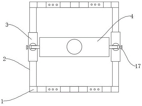
FIG. 1 is a schematic view of the overall structure of the present invention;
FIG. 2 is an internal schematic view of a first support bar of the present invention;
FIG. 3 is a schematic view of a first support bar connection of the present invention;
FIG. 4 is a schematic view of the internal structure of a second support rod according to the present invention;
fig. 5 is a schematic structural view of a three-dimensional connecting plate of the utility model.
Description of reference numerals: 1. a first support bar; 2. a second support bar; 3. a telescopic box body; 4. a connecting plate; 5. a wheel groove; 6. an adjustment groove; 7. an adjustment hole; 9. adjusting the box body; 10. a spring; 11. a chute; 12. a fixing hole; 13. a first rotating groove; 14. rotating the block; 15. an L-shaped toothed plate; 16. a gear; 17. fixing the knob; 18. a second rotating groove; 19. a rotating rod; 20. a through hole; 21. adjusting a rod; 22. the main pole.
Detailed Description
The present invention is described in detail below, and technical solutions in the embodiments of the present invention are clearly and completely described, and it is obvious that the described embodiments are only a part of the embodiments of the present invention, and not all of the embodiments. All other embodiments, which can be derived by a person skilled in the art from the embodiments given herein without making any creative effort, shall fall within the protection scope of the present invention.
The utility model provides a narrow-gauge bogie with strong bearing capacity through improvement, and the technical scheme of the utility model is as follows:
the first embodiment is as follows:
as shown in fig. 1 to 5, the narrow gauge bogie with strong bearing capacity comprises a support frame, the support frame comprises two regulating box bodies 9, sliding grooves 11 are symmetrically formed in two sides of each regulating box body 9, a first supporting rod 1 is slidably connected inside each sliding groove 11, a plurality of springs 10 are fixedly connected to the top of one end of each first supporting rod 1, the other end of each spring 10 is fixedly connected to the inner top of each regulating box body 9, each two first supporting rods 1 are slidably connected to the regulating box body 9, and the two first supporting rods 1 are connected through the springs 10 to have staggered buffering capacity, so that the narrow gauge bogie can be adapted to fit when the heights of two sides of the train are different when the train turns.
Further, every adjustment tank 6, every have all been seted up to the other end of first bracing piece 1 adjustment tank 6 all rotates through the pivot to be connected with second bracing piece 2, and per two correspond the equal common sliding connection of the other end of second bracing piece 2 has flexible box 3, every the equal fixedly connected with L type rack 15 of the other end of second bracing piece 2 corresponds two the common meshing of L type rack 15 is connected with gear 16, gear 16's center runs through adjusting box 9 fixedly connected with fixed knob 17 through the pivot, and the equal fixedly connected with L type rack 15 of per two second bracing pieces 2 passes through gear 16 control, can adjust the distance between two second bracing pieces 2 and adjust the size.
Further, every first rotor groove 13 has all been seted up at the top of adjusting box 9, every the inside of first rotor groove 13 all rotates and is connected with turning block 14, every turning block 14's top all rotates through the pivot and is connected with bull stick 19, and turning block 14 can rotate at the top of adjusting box 9, can guarantee that bull stick 19 can corresponding motion when the support frame takes place corresponding motion because the train operation.
Further, the inside of support frame is equipped with connecting plate 4, second rotation groove 18, every have been seted up to the bilateral symmetry of connecting plate 4 second rotation groove 18 all rotates through the pivot and is connected with corresponding bull stick 19 rotation, through-hole 20 has been seted up at the center of connecting plate 4, and connecting plate 4 is connected with bull stick 19, and the nimble motion of bull stick 19 can guarantee that the support frame is when moving, and connecting plate 4 can not receive its influence, and the train that can laminate always can not take place to rock, guarantees its stability.
Further, every first bracing piece 1 is including mobile jib 22 and regulation pole 21, every race 5 has all been seted up on the mobile jib 22, every fixed orifices 12 have all been seted up to mobile jib 22's one end, every three regulation hole 7 has all been seted up on adjusting the pole 21, every mobile jib 22 all is sliding connection with adjusting pole 21 and passes through the bolt fixed, and race 5 can guarantee that the wheel can normally rotate, and regulation pole 21 on the mobile jib 22 can realize adjusting the size with adjusting the 7 cooperations of regulation hole on the pole 21.
The working principle is as follows: with whole support frame fixed mounting on the bogie, again with support frame and train fixed connection, adjust fixed knob 17 and drive gear 16, thereby it adjusts the size to drive L type rack board 15 and adjust the distance between two second bracing pieces 2, adjust pole 21 on the mobile jib 22 and adjust the regulation hole 7 on the pole 21 and can realize adjusting the size through the bolt cooperation, per two first bracing pieces 1 common with adjust box 9 sliding connection, it has the buffer capacity of dislocation to connect two first bracing pieces 1 through spring 10, it adapts to the laminating when the both sides height differs when the train turns to enable it, connecting plate 4 is connected with bull stick 19, the nimble motion of bull stick 19 can guarantee that the support frame is when the motion, connecting plate 4 can not receive its influence, can laminate the train always and can not take place to rock, guarantee its stability.
The previous description is provided to enable any person skilled in the art to make or use the present invention. Various modifications to these embodiments will be readily apparent to those skilled in the art, and the generic principles defined herein may be applied to other embodiments without departing from the spirit or scope of the utility model. Thus, the present invention is not intended to be limited to the embodiments shown herein but is to be accorded the widest scope consistent with the principles and novel features disclosed herein.