CN215941237U - Stamping die for hardware processing of planetary reducer - Google Patents

Stamping die for hardware processing of planetary reducer Download PDF

Info

Publication number
CN215941237U
CN215941237U CN202121615917.4U CN202121615917U CN215941237U CN 215941237 U CN215941237 U CN 215941237U CN 202121615917 U CN202121615917 U CN 202121615917U CN 215941237 U CN215941237 U CN 215941237U
Authority
CN
China
Prior art keywords
stamping die
planetary reducer
hardware processing
sets
push plate
Prior art date
Legal status (The legal status is an assumption and is not a legal conclusion. Google has not performed a legal analysis and makes no representation as to the accuracy of the status listed.)
Active
Application number
CN202121615917.4U
Other languages
Chinese (zh)
Inventor
刘明
Current Assignee (The listed assignees may be inaccurate. Google has not performed a legal analysis and makes no representation or warranty as to the accuracy of the list.)
Zhejiang Yixue Refrigeration Equipment Co ltd
Original Assignee
Tianjin Liebherr Transmission Technology Co ltd
Priority date (The priority date is an assumption and is not a legal conclusion. Google has not performed a legal analysis and makes no representation as to the accuracy of the date listed.)
Filing date
Publication date
Application filed by Tianjin Liebherr Transmission Technology Co ltd filed Critical Tianjin Liebherr Transmission Technology Co ltd
Priority to CN202121615917.4U priority Critical patent/CN215941237U/en
Application granted granted Critical
Publication of CN215941237U publication Critical patent/CN215941237U/en
Active legal-status Critical Current
Anticipated expiration legal-status Critical

Links

Images

Landscapes

  • Mounting, Exchange, And Manufacturing Of Dies (AREA)

Abstract

本实用新型涉及五金加工的技术领域,特别是涉及一种行星减速机五金加工用冲压模具,其通过设置此设备,便于将冲压成型后的五金件在冲压模具内取出,操作较简单,提高其实用性;包括冲压模具、螺环、螺杆、推板、摇片、摇把、把套和四组固定片,冲压模具内部底端中部连通设置有推板槽,螺环安装在冲压模具底端中部,螺杆与螺环螺装连接,推板可转动安装在螺杆顶端,推板位于推板槽内部,摇片安装在螺杆底端,摇把可转动安装在摇片底端,把套安装在摇把上,四组固定片分别安装在冲压模具前端和后端下部左侧和右侧。
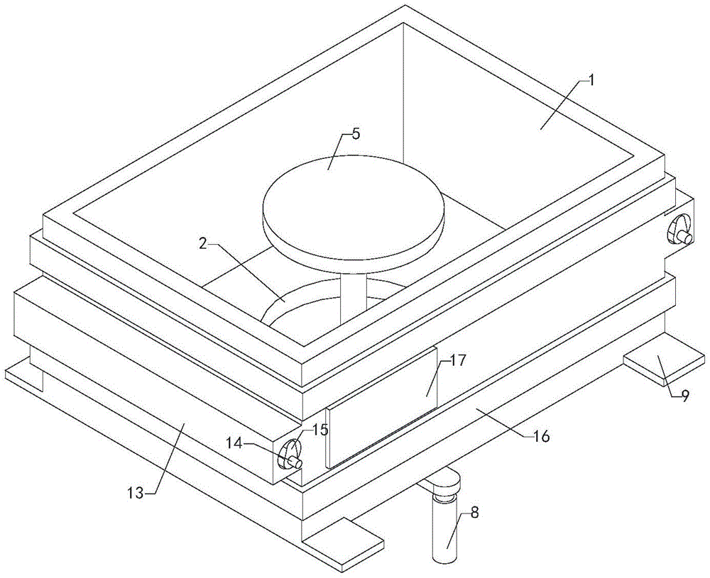
Figure 202121615917

The utility model relates to the technical field of metal processing, in particular to a stamping die for planetary reducer metal processing. By setting the device, it is convenient to take out the stamped and formed hardware in the stamping die, the operation is relatively simple, and the efficiency is improved. Practicality: including stamping die, screw ring, screw, push plate, rocker, crank handle, handle cover and four sets of fixed pieces, the middle of the bottom end of the stamping die is connected with a push plate groove, and the screw ring is installed at the bottom end of the stamping die In the middle, the screw is screwed with the screw ring, the push plate is rotatably installed at the top of the screw, the push plate is located inside the push plate groove, the rocker is installed at the bottom end of the screw, the rocker is rotatably installed at the bottom end of the rocker, and the handle is installed at the bottom of the rocker. On the crank handle, four sets of fixing pieces are respectively installed on the left and right sides of the lower front and rear ends of the stamping die.

Figure 202121615917

Description

Stamping die for hardware processing of planetary reducer
Technical Field
The utility model relates to the technical field of hardware processing, in particular to a stamping die for hardware processing of a planetary reducer.
Background
The planetary reducer is an industrial product with wide application, and can reduce the rotating speed of a motor and increase the output torque. The planetary reducer can be used as a matched component for industries such as hoisting, digging, transportation, building and the like.
Hardware workpiece among the planetary reducer is stamping forming, but current hardware workpiece is stamping forming back in the mould, and it is easy adhesion at the mould inner wall to inconvenient taking out it, the operation is more inconvenient.
Disclosure of Invention
In order to solve the technical problems, the utility model provides the stamping die for the hardware processing of the planetary reducer, which is convenient for taking out the stamped hardware in the stamping die, is simple to operate and improves the practicability of the stamping die.
The utility model discloses a stamping die for hardware processing of a planetary reducer, which comprises a stamping die, a spiral ring, a screw, a push plate, a rocking piece, a crank, a handle sleeve and four groups of fixing pieces, wherein the middle part of the bottom end in the stamping die is communicated with a push plate groove, the spiral ring is installed in the middle part of the bottom end of the stamping die, the screw is in threaded connection with the spiral ring, the push plate is rotatably installed at the top end of the screw and is positioned in the push plate groove, the rocking piece is installed at the bottom end of the screw, the crank is rotatably installed at the bottom end of the rocking piece, the handle sleeve is installed on the crank, and the four groups of fixing pieces are respectively installed at the left side and the right side of the lower parts of the front end and the rear end of the stamping die.
According to the stamping die for hardware processing of the planetary reducer, the spiral ring groove is formed in the middle of the bottom end of the push plate and corresponds to the upper portion of the spiral ring.
The stamping die for hardware processing of the planetary reducer further comprises an oil injection nozzle, and the output end of the oil injection nozzle is communicated with the spiral ring.
The utility model relates to a stamping die for hardware processing of a planetary reducer, which further comprises an oil injection cap, wherein the oil injection cap is arranged on an oil injection nozzle.
The stamping die for the hardware processing of the planetary reducer further comprises two groups of fixed boxes, two groups of rotating shafts and two groups of eccentric wheels, wherein the two groups of fixed boxes are respectively arranged at the left end and the right end of the stamping die, the two groups of rotating shafts are both arranged at the output end of the motor, the two groups of eccentric wheels are arranged on the two groups of rotating shafts, and the two groups of eccentric wheels are positioned inside the two groups of fixed boxes.
The stamping die for the hardware processing of the planetary reducer further comprises a reinforcing strip, and the reinforcing strip is arranged on the outer side of the stamping die.
The utility model relates to a stamping die for hardware processing of a planetary reducer, which further comprises an information board, wherein the information board is arranged at the front end of the stamping die.
The utility model relates to a stamping die for hardware processing of a planetary reducer, which is made of hard alloy materials.
Compared with the prior art, the utility model has the beneficial effects that: pass four stationary blades of group with the bolt and fix on the workstation, then with the leading-in stamping forming that carries out of raw materials to stamping die inside, later rotate through the crank and shake the piece, it then drives the screw rod and rotate to shake the piece, the screw rod then with the spiro union dress, the screw rod then drives the push pedal upward movement, the push pedal then upwards ejecting with stamping die interior stamping forming's hardware, then the manual work takes off it, through setting up this equipment, be convenient for take out the hardware after the stamping forming in stamping die, the operation is simpler, the practicality is improved.
Drawings
FIG. 1 is an isometric view of the present invention;
FIG. 2 is a schematic front view of the structure of FIG. 1;
FIG. 3 is a schematic diagram of the right side cross-sectional structure of FIG. 1;
in the drawings, the reference numbers: 1. a stamping die; 2. a push plate groove; 3. a spiro ring; 4. a screw; 5. pushing the plate; 6. shaking the slices; 7. a crank; 8. covering the handlebar; 9. a fixing sheet; 10. a spiral ring groove; 11. an oil injection nozzle; 12. an oil injection cap; 13. a fixed box; 14. a rotating shaft; 15. an eccentric wheel; 16. reinforcing the strips; 17. an information board.
Detailed Description
The following detailed description of embodiments of the present invention is provided in connection with the accompanying drawings and examples. The following examples are intended to illustrate the utility model but are not intended to limit the scope of the utility model.
As shown in fig. 1 to 3, the stamping die for hardware processing of the planetary reducer comprises a stamping die 1, a spiral ring 3, a screw rod 4, a push plate 5, a rocker 6, a crank 7, a handle sleeve 8 and four fixing pieces 9, wherein the middle of the bottom end inside the stamping die 1 is communicated with a push plate groove 2, the spiral ring 3 is installed in the middle of the bottom end of the stamping die 1, the screw rod 4 is in threaded connection with the spiral ring 3, the push plate 5 is rotatably installed at the top end of the screw rod 4, the push plate 5 is located inside the push plate groove 2, the rocker 6 is installed at the bottom end of the screw rod 4, the crank 7 is rotatably installed at the bottom end of the rocker 6, the handle sleeve 8 is installed on the crank 7, and the four fixing pieces 9 are respectively installed on the left side and the right side of the lower parts of the front end and the rear end of the stamping die 1; pass four stationary blades of group 9 with the bolt and fix on the workstation, then with the leading-in stamping forming that carries out to stamping die 1 inside of raw materials, later rotate through crank 7 and shake piece 6, it then drives screw rod 4 and rotates to shake piece 6, screw rod 4 then with 3 spiral shell dresses of spiro union, screw rod 4 then drives push pedal 5 upward movements, push pedal 5 then upwards ejecting with stamping die 1 interior stamping forming's hardware, then the manual work takes off it, through setting up this equipment, be convenient for take out stamping die 1 with the hardware after the stamping forming, the operation is simpler, the practicality is improved.
According to the stamping die for hardware processing of the planetary reducer, the spiral ring groove 10 is formed in the middle of the bottom end of the push plate 5, and the spiral ring groove 10 corresponds to the upper portion of the spiral ring 3; through setting up spiral shell ring groove 10, can make push pedal 5 keep flat to push pedal groove 2 insidely to avoid its stamping forming effect that influences the hardware.
The stamping die for hardware processing of the planetary reducer further comprises an oil injection nozzle 11, and the output end of the oil injection nozzle 11 is communicated with the spiral ring 3; the oil nozzle 11 is arranged, so that the oil can be injected and lubricated to the spiral ring 3 and the screw rod 4.
The stamping die for the hardware processing of the planetary reducer further comprises an oil injection cap 12, wherein the oil injection cap 12 is covered on the oil injection nozzle 11; by providing the oil filling cap 12, the function of dust prevention for the oil filling nozzle 11 can be achieved.
The stamping die for the hardware processing of the planetary reducer further comprises two groups of fixed boxes 13, two groups of rotating shafts 14 and two groups of eccentric wheels 15, wherein the two groups of fixed boxes 13 are respectively arranged at the left end and the right end of the stamping die 1, the two groups of rotating shafts 14 are both arranged at the output end of a motor, the two groups of eccentric wheels 15 are arranged on the two groups of rotating shafts 14, and the two groups of eccentric wheels 15 are positioned inside the two groups of fixed boxes 13; through opening the motor, the motor then drives two sets of pivots 14 and rotates, and two sets of pivots 14 then drive two sets of eccentric wheels 15 and rotate, and two sets of eccentric wheels 15 then drive two sets of fixed case 13 vibrations, and two sets of fixed case 13 then drive stamping die 1 whole vibrations, are convenient for carry out the demoulding to stamping forming's hardware in stamping die 1.
The stamping die for the hardware processing of the planetary reducer further comprises a reinforcing strip 16, wherein the reinforcing strip 16 is arranged on the outer side of the stamping die 1; by providing the reinforcing strip 16, the entire punching die 1 can be reinforced.
The utility model relates to a stamping die for hardware processing of a planetary reducer, which further comprises an information board 17, wherein the information board 17 is arranged at the front end of the stamping die 1; by arranging the information board 17, the staff can know the use method and the attention of the equipment conveniently.
According to the stamping die for hardware processing of the planetary reducer, disclosed by the utility model, the stamping die 1 is made of hard alloy; the alloy has higher hardness and is not easy to deform and damage.
When the stamping die for machining the hardware of the planetary reducer works, bolts penetrate through four fixing pieces 9 and are fixed on a workbench, then raw materials are guided into the stamping die 1 to be subjected to stamping forming, then the rocking piece 6 is rotated through the crank 7, the rocking piece 6 drives the screw rod 4 to rotate, the screw rod 4 is screwed with the spiral ring 3, the screw rod 4 drives the push plate 5 to move upwards, the push plate 5 pushes out the hardware subjected to stamping forming in the stamping die 1 upwards, and then the hardware is taken down manually, so that the hardware subjected to stamping forming can be taken out from the stamping die 1 conveniently.
The stamping die for hardware processing of the planetary reducer is provided with common mechanical mounting modes, connection modes or arrangement modes, and can be implemented as long as beneficial effects of the stamping die can be achieved.
The above description is only a preferred embodiment of the present invention, and it should be noted that, for those skilled in the art, several modifications and variations can be made without departing from the technical principle of the present invention, and these modifications and variations should also be regarded as the protection scope of the present invention.

Claims (8)

1. A stamping die for hardware processing of a planetary reducer is characterized by comprising a stamping die (1), a spiral ring (3), a screw rod (4) and a push plate (5), rocking piece (6), crank (7), handle cover (8) and four stationary blades of group (9), stamping die (1) inside bottom middle part intercommunication is provided with push pedal groove (2), install at stamping die (1) bottom middle part spiro union (3), screw rod (4) are connected with spiro union (3) spiral shell dress, push pedal (5) rotatable the installation on screw rod (4) top, push pedal (5) are located push pedal groove (2) inside, install in screw rod (4) bottom rocking piece (6), rotatable the installation in rocking piece (6) bottom crank (7), install on crank (7) handle cover (8), four stationary blades of group (9) are installed respectively in stamping die (1) front end and rear end lower part left side and right side.
2. The stamping die for the hardware processing of the planetary reducer as claimed in claim 1, wherein a spiral ring groove (10) is arranged in the middle of the bottom end of the push plate (5), and the spiral ring groove (10) corresponds to the upper portion of the spiral ring (3).
3. The stamping die for the hardware processing of the planetary reducer as claimed in claim 2, further comprising an oil injection nozzle (11), wherein an output end of the oil injection nozzle (11) is communicated with the spiral ring (3).
4. The stamping die for the hardware processing of the planetary reducer as claimed in claim 3, further comprising an oil injection cap (12), wherein the oil injection cap (12) is covered on the oil injection nozzle (11).
5. The stamping die for the hardware processing of the planetary reducer as claimed in claim 4, further comprising two sets of fixed boxes (13), two sets of rotating shafts (14) and two sets of eccentric wheels (15), wherein the two sets of fixed boxes (13) are respectively installed at the left end and the right end of the stamping die (1), the two sets of rotating shafts (14) are both installed at the output end of the motor, the two sets of eccentric wheels (15) are installed on the two sets of rotating shafts (14), and the two sets of eccentric wheels (15) are located inside the two sets of fixed boxes (13).
6. The stamping die for the hardware processing of the planetary reducer as claimed in claim 5, further comprising a reinforcing strip (16), wherein the reinforcing strip (16) is installed on the outer side of the stamping die (1).
7. The stamping die for the hardware processing of the planetary reducer as claimed in claim 6, further comprising an information board (17), wherein the information board (17) is installed at the front end of the stamping die (1).
8. The stamping die for the hardware processing of the planetary reducer as claimed in claim 7, wherein the stamping die (1) is made of hard alloy.
CN202121615917.4U 2021-07-15 2021-07-15 Stamping die for hardware processing of planetary reducer Active CN215941237U (en)

Priority Applications (1)

Application Number Priority Date Filing Date Title
CN202121615917.4U CN215941237U (en) 2021-07-15 2021-07-15 Stamping die for hardware processing of planetary reducer

Applications Claiming Priority (1)

Application Number Priority Date Filing Date Title
CN202121615917.4U CN215941237U (en) 2021-07-15 2021-07-15 Stamping die for hardware processing of planetary reducer

Publications (1)

Publication Number Publication Date
CN215941237U true CN215941237U (en) 2022-03-04

Family

ID=80437522

Family Applications (1)

Application Number Title Priority Date Filing Date
CN202121615917.4U Active CN215941237U (en) 2021-07-15 2021-07-15 Stamping die for hardware processing of planetary reducer

Country Status (1)

Country Link
CN (1) CN215941237U (en)

Similar Documents

Publication Publication Date Title
CN215941237U (en) Stamping die for hardware processing of planetary reducer
CN105015005B (en) The servo-type fly press that a kind of many motors multiscrew independently drives
CN203896080U (en) Fixing seat for electromotor
CN107088664B (en) A kind of numerical control gang drill device
CN211599448U (en) Telescopic tooth box
CN210629260U (en) Electric jar turns back
CN210686893U (en) Electric linear push rod mechanism based on lead screw transmission technology
CN109570325B (en) Gantry high-speed punch press
CN111688194A (en) 3D printing platform
CN207239756U (en) A kind of fixture of highly-efficient processing punch
CN214720871U (en) Cutting device is used in fin processing
CN214863931U (en) Feeding machine feed inlet protector
CN204842610U (en) Key tartar for tooth punching machine tooth punching machine construct
CN209344938U (en) A kind of toothed gearing electric motor of antidetonation
CN2926134Y (en) Driver of spiral conveyor
CN215360066U (en) Forming die for preparing high-heat-conduction gasket
CN112775789A (en) Processing equipment for efficiently processing inner concave surface of aluminum alloy cornerite block
CN206936501U (en) A kind of rotatable aluminum product cutting device
CN111113990A (en) Rotary extrusion's aluminium scrap recovery unit
CN2152628Y (en) New-structure multifunction punching and shearing machine
CN113932001A (en) Motor gear box device applied to wind power generation system
CN219852214U (en) A zinc alloy die-casting mold for nut die-casting molding
CN216461593U (en) Hollow rivet processing die
CN224168857U (en) Electric powerful cutting pliers
CN104801954B (en) Operating method of micro reduction motor assembling machine

Legal Events

Date Code Title Description
GR01 Patent grant
GR01 Patent grant
TR01 Transfer of patent right

Effective date of registration: 20240820

Address after: No. 199, Sigen Village, Shihuang Town, Shengzhou City, Zhejiang Province, China 312471

Patentee after: Xu Jianhua

Country or region after: China

Patentee after: Luo Mixue

Address before: 300380 No. 1, No. 19, Fengze Road, Zhangjiawo Industrial Zone, Xiqing District, Tianjin

Patentee before: Tianjin Liebherr Transmission Technology Co.,Ltd.

Country or region before: China

TR01 Transfer of patent right

Effective date of registration: 20241122

Address after: No. 1408, Xianhu Road, Sanjiang Street, Shengzhou City, Shaoxing City, Zhejiang Province 312400

Patentee after: Zhejiang Yixue Refrigeration Equipment Co.,Ltd.

Country or region after: China

Address before: No. 199, Sigen Village, Shihuang Town, Shengzhou City, Zhejiang Province, China 312471

Patentee before: Xu Jianhua

Country or region before: China

Patentee before: Luo Mixue