CN216007796U - Formwork support system - Google Patents
Formwork support system Download PDFInfo
- Publication number
- CN216007796U CN216007796U CN202122293990.0U CN202122293990U CN216007796U CN 216007796 U CN216007796 U CN 216007796U CN 202122293990 U CN202122293990 U CN 202122293990U CN 216007796 U CN216007796 U CN 216007796U
- Authority
- CN
- China
- Prior art keywords
- rod
- pole
- support system
- screw rod
- horizontal
- Prior art date
- Legal status (The legal status is an assumption and is not a legal conclusion. Google has not performed a legal analysis and makes no representation as to the accuracy of the status listed.)
- Active
Links
- 238000009415 formwork Methods 0.000 title claims abstract description 23
- 230000008093 supporting effect Effects 0.000 claims description 17
- 238000005096 rolling process Methods 0.000 abstract description 13
- 238000010276 construction Methods 0.000 abstract description 4
- 238000004519 manufacturing process Methods 0.000 abstract description 4
- 238000000034 method Methods 0.000 abstract description 4
- 229910000831 Steel Inorganic materials 0.000 description 9
- 239000010959 steel Substances 0.000 description 9
- 239000002023 wood Substances 0.000 description 3
- XEEYBQQBJWHFJM-UHFFFAOYSA-N Iron Chemical compound [Fe] XEEYBQQBJWHFJM-UHFFFAOYSA-N 0.000 description 2
- 230000000694 effects Effects 0.000 description 2
- 235000017166 Bambusa arundinacea Nutrition 0.000 description 1
- 235000017491 Bambusa tulda Nutrition 0.000 description 1
- 241001330002 Bambuseae Species 0.000 description 1
- 235000015334 Phyllostachys viridis Nutrition 0.000 description 1
- 239000011425 bamboo Substances 0.000 description 1
- 230000009286 beneficial effect Effects 0.000 description 1
- 238000009435 building construction Methods 0.000 description 1
- 229910052742 iron Inorganic materials 0.000 description 1
- 239000000463 material Substances 0.000 description 1
- 230000000149 penetrating effect Effects 0.000 description 1
Images


Landscapes
- Forms Removed On Construction Sites Or Auxiliary Members Thereof (AREA)
Abstract
The utility model belongs to the technical field of the technique of construction and specifically relates to a formwork support system is related to, including the scaffold frame, the scaffold frame includes many pole settings and many horizontal poles, pole setting and horizontal pole pass through fastener fixed connection, the fixed strutting arrangement that is provided with on the roof of pole setting, strutting arrangement includes the outer pole, the screw rod, fixed plate and horizon bar, the outer pole sets up on the roof of pole setting, screw rod threaded connection is on the outer pole, be provided with the rolling disc on the roof of outer pole, rolling disc and screw rod threaded connection, be provided with the fixed plate on the roof of screw rod, be provided with the backup pad on the fixed plate lateral wall, horizon bar and backup pad and fixed plate joint. The staff with the horizon bar joint between fixed plate and two backup pads, then rotate the rolling disc, make the horizon bar support tightly with the template, the loading power that the template received transmits the pole setting again through horizon bar and strutting arrangement on, the loading power direct action that the template received effectively prevents the production of eccentricity on the horizon bar, improves template bearing structure's stability.
Description
Technical Field
The application relates to the technical field of building construction, in particular to a formwork support system.
Background
In the form supporting structure for concrete cast-in-place construction in construction, steel or wood beams are generally assembled into form support brackets, steel or wood rods are used for building scaffolds to form support brackets, and the steel form is matched for concrete construction.
Referring to fig. 1, currently, when supporting a top formwork, a fastener-type steel pipe support structure is often adopted, that is, a plurality of cross rods 12 and upright rods 11 are adopted to fix and erect a steel pipe scaffold 1 through fasteners, and the tops of the upright rods 11 are directly abutted against the bottom of the formwork.
In view of the above-mentioned related art, the inventors found that the following drawbacks exist: on the load power that the template received directly transmits the pole setting, the pole setting can produce the eccentricity at this in-process, and the eccentricity can cause certain moment of flexure to the pole setting, leads to the pole setting slope, and template bearing structure stability is relatively poor.
SUMMERY OF THE UTILITY MODEL
In order to improve the stability of formwork support structure, the present application provides a formwork support system.
The application provides a template support system adopts following technical scheme:
a formwork support system comprises a scaffold, the scaffold comprises a plurality of vertical rods and a plurality of cross rods, the vertical rods and the cross rods are fixedly connected through fasteners, a support device is fixedly arranged on the top wall of each vertical rod, the support device comprises an outer rod, a screw rod, a fixing plate and a horizontal rod, the outer rod is fixedly arranged on the top wall of each vertical rod along the vertical direction, the screw rod is coaxially and slidably arranged at one end, away from the vertical rods, of the outer rod in a penetrating mode, the screw rod is in threaded connection with the outer rod, a rotating disc is rotatably arranged on the top wall of the outer rod, the inner side wall of the rotating disc is in threaded connection with the screw rod, the fixing plate is fixedly arranged on the top wall of the screw rod along the horizontal direction, support plates are fixedly arranged on the side walls on the two sides of the fixing plate, the bottom wall of the horizontal rod is abutted to the top wall of the fixing plate, the side walls on the two sides of the horizontal rod are respectively abutted to the two support plates, the top wall of the horizontal rod is abutted against the bottom wall of the template.
Through adopting above-mentioned technical scheme, the staff with the horizon bar joint between fixed plate and two backup pads, then rotate the rolling disc, make the screw rod drive the horizon bar to the direction removal that is close to the template to make horizon bar and template support tightly, the loading power that the template received transmits the pole setting again through horizon bar and strutting arrangement on, the loading power that the template received directly acts on the horizon bar, effectively prevents the production of eccentricity, improves template bearing structure's stability.
Optionally, a plurality of anti-slip grooves are formed in the rotating disc at intervals along the circumferential direction of the rotating disc.
Through adopting above-mentioned technical scheme, the area of contact of staff with the rolling disc has been increased in the antiskid groove, makes things convenient for the staff to rotate the rolling disc.
Optionally, a fixing groove is formed in the side wall of the fixing plate, two movable plates are fixedly arranged on the side wall, close to each other, of the support plate, the movable plates are connected into the fixing groove in a sliding mode along the depth direction of the fixing groove, limiting bolts used for limiting sliding of the support plate are arranged on the support plate, through holes are formed in the support plate, and the limiting bolts penetrate through the through holes in the support plate and are in threaded connection with the side wall of the fixing plate.
Through adopting above-mentioned technical scheme, the staff places the horizon bar on the diapire of fixed plate, then uses tools to rotate spacing bolt, makes spacing bolt drive the backup pad and removes to the direction of the diapire that is close to the holding tank to the lateral wall of the one side that makes two backup pads be close to each other supports tightly with the lateral wall of horizon bar, thereby fixes the horizon bar between two backup pads, and the staff can be according to the interval between the adjacent backup pad of the size regulation of removal board, has improved strutting arrangement's suitability.
Optionally, one end of the limiting bolt, which is far away from the fixing plate, is fixedly provided with a rotating sheet.
Through adopting above-mentioned technical scheme, the staff rotates spacing bolt through the rotor plate and makes the movable plate in the backup pad slide along the degree of depth direction of holding tank, has saved the working process that the staff uses the instrument to rotate spacing bolt, makes things convenient for the staff to rotate spacing bolt.
Optionally, a cross brace is fixedly arranged on the outer side wall of the scaffold.
Through adopting above-mentioned technical scheme, the bridging can effectively ensure scaffold overall structure indeformable, improves template bearing structure's stability.
Optionally, an included angle between the cross brace and the cross bar is 45 degrees to 60 degrees.
Through adopting above-mentioned technical scheme, through a large amount of theoretical analysis, experiments and actual operation, when the contained angle between bridging and the horizontal pole was 45 degrees to 60 degrees, the bridging was the best to the support effect of scaffold.
Optionally, a base plate is arranged on the bottom wall of the upright rod.
Through adopting above-mentioned technical scheme, the backing plate can prevent effectively that the uneven condition of sinking from appearing in ground to can prevent effectively that the pole setting from taking place the phenomenon of removing for ground, improved template bearing structure's stability.
Optionally, a sleeve is fixedly arranged on the top wall of the base plate, and the vertical rod is clamped in the sleeve.
Through adopting above-mentioned technical scheme, when using the backing plate, with pole setting joint to the sleeve in, can dismantle the connection between backing plate and the pole setting, make things convenient for the staff to accomodate pole setting and backing plate respectively.
In summary, the present application includes at least one of the following beneficial technical effects:
the horizontal rod is clamped between the fixed plate and the two supporting plates by a worker, then the rotating disc is rotated, the screw rod drives the horizontal rod to move towards the direction close to the template, the horizontal rod is abutted against the template, the load force borne by the template is transmitted to the vertical rod through the horizontal rod and the supporting device, and the load force borne by the template directly acts on the horizontal rod, so that the eccentric distance is effectively prevented from being generated, and the stability of a template supporting structure is improved;
the cross braces can effectively ensure that the overall structure of the scaffold is not deformed, and the stability of the template supporting structure is improved;
the backing plate can effectively prevent the condition that uneven subsidence appears in ground to can effectively prevent that the pole setting from taking place the phenomenon of removal for ground, improved template bearing structure's stability.
Drawings
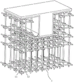
Fig. 1 is a schematic view of the overall structure of the prior art.
Fig. 2 is a schematic view of the overall structure of the formwork support system according to the embodiment of the present application.
Fig. 3 is a partially enlarged schematic view of a portion a in fig. 1.
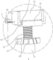
Fig. 4 is a partially enlarged schematic view of a portion B in fig. 2.
Description of reference numerals: 1. a scaffold; 11. erecting a rod; 12. a cross bar; 2. a support device; 21. an outer rod; 22. a screw; 23. a fixing plate; 231. a fixing groove; 24. a horizontal bar; 25. rotating the disc; 251. an anti-slip groove; 26. a support plate; 3. moving the plate; 4. a limit bolt; 5. a rotating sheet; 6. a scissor support; 7. a base plate; 8. a sleeve.
Detailed Description
The present application is described in further detail below with reference to figures 2-4.
The embodiment of the application discloses a template support system. Referring to fig. 2 and 3, the formwork support system includes a scaffold 1, the scaffold 1 includes a plurality of uprights 11 and a plurality of crossbars 12, the uprights 11 are installed on the ground in a vertical array, and the crossbars 12 are installed on the uprights 11 in a horizontal direction. The adjacent cross bars 12 and the vertical bars 11 are fixedly connected through fasteners. The support means 2 for supporting the formwork are mounted on the uppermost upright 11.
Referring to fig. 2 and 4, the supporting device 2 includes an outer rod 21, a screw 22, a fixing plate 23 and a horizontal rod 24, the outer rod 21 is made of a steel pipe with a circular cross section, and the horizontal rod 24 is made of square wood. The outer pole 21 is welded on the top wall of the upright pole 11 along the vertical direction, and the top wall of the outer pole 21 is provided with a threaded hole along the vertical direction. The screw rod 22 is coaxially and slidably arranged at one end of the outer rod 21 far away from the upright rod 11, and the screw rod 22 is in threaded connection with the outer rod 21. Install the rolling disc 25 on the outer pole 21, seted up the perforation on the roof of rolling disc 25, the coaxial rotation of rolling disc 25 is installed on the roof of outer pole 21, and screw rod 22 passes the perforation of rolling disc 25, and the inside wall and the screw rod 22 threaded connection of rolling disc 25. In order to facilitate the rotation of the rotating disc 25 by the worker, a plurality of anti-slip grooves 251 are formed in the rotating disc 25 at intervals along the circumferential direction of the rotating disc 25, the anti-slip grooves 251 increase the contact area between the worker and the rotating disc 25, and the worker can rotate the rotating disc 25 conveniently.
Referring to fig. 2 and 4, the fixed plate 23 is welded to the top wall of the screw 22, the support plates 26 are mounted on the side walls of both sides of the fixed plate 23, and the moving plate 3 is integrally formed on the side walls of the two support plates 26 close to each other, so that an L-shape is formed between the support plates 26 and the moving plate 3. A fixing groove 231 for accommodating the moving plate 3 is formed on a sidewall of the fixing plate 23, and the moving plate 3 is slidably coupled in the fixing groove 231 along a depth direction of the fixing groove 231. The supporting plate 26 is provided with a limiting bolt 4 used for limiting the sliding of the supporting plate 26, the supporting plate 26 is provided with a through hole, the side wall of the fixing plate 23 is provided with a threaded hole, and the limiting bolt 4 penetrates through the through hole in the supporting plate 26 and is in threaded connection with the side wall of the fixing plate 23. In order to rotate the limiting bolt 4 for the convenience of workers, the rotating sheet 5 is welded at one end, away from the fixed plate 23, of the limiting bolt 4, the working process that the workers use tools to rotate the limiting bolt 4 is omitted, and the workers can rotate the limiting bolt 4 conveniently. The staff places horizontal rod 24 on the diapire of fixed plate 23, then improve and rotate rotor plate 5 and rotate limit bolt 4, make limit bolt 4 drive backup pad 26 to the direction removal of the diapire that is close to the holding tank, and make the lateral wall of the one side that two backup pads 26 are close to each other support tightly with the lateral wall of horizontal rod 24, thereby fix horizontal rod 24 between two backup pads 26, the staff can adjust the interval between the adjacent backup pad 26 according to the size of movable plate 3, strutting arrangement 2's suitability has been improved.
Referring to fig. 2 and 4, the bottom wall of the horizontal bar 24 abuts against the top wall of the fixed plate 23, the side walls on both sides of the horizontal bar 24 abut against the two support plates 26, and the top wall of the horizontal bar 24 abuts against the bottom wall of the formwork. The staff is with the joint of horizontal pole 24 between fixed plate 23 and two backup pads 26, then rotates rolling disc 25, makes screw rod 22 drive horizontal pole 24 to the direction removal that is close to the template to make horizontal pole 24 support tightly with the template, the loading power that the template received transmits pole setting 11 again through horizontal pole 24 and strutting arrangement 2 on, the loading power that the template received directly acts on horizontal pole 24, effectively prevents the production of eccentricity, improves template bearing structure's stability.
Referring to fig. 1, in order to improve the stability of the overall structure of the scaffold 1, a cross brace 6 is installed on the outermost scaffold 1, the cross brace 6 includes two steel pipes inclined to each other, and the cross brace 6 is fixedly connected with a vertical rod 11 on the scaffold 1 through a fastener. In order to optimize the supporting effect of the cross arm 6 on the scaffold 1, the included angle between the cross arm 6 and the cross bar 12 is 45 degrees to 60 degrees, in this embodiment, the included angle between the cross arm 6 and the cross bar 12 is 45 degrees.
Referring to fig. 1 and 2, a backing plate 7 is installed between the upright rod 11 and the ground, the backing plate 7 can be made of bamboo or steel plates, in the embodiment, the backing plate 7 is made of steel plates, the backing plate 7 can effectively prevent the ground from sinking unevenly, the upright rod 11 can be effectively prevented from moving relative to the ground, and the stability of the formwork supporting structure is improved. Integrated into one piece has sleeve 8 on the roof of backing plate 7, and sleeve 8 is the pipe of iron material, has seted up the perforation on the roof of pipe, and the pole setting 11 joint is to the perforation of sleeve 8. When using backing plate 7, with pole setting 11 joint to sleeve 8 in, can dismantle the connection between backing plate 7 and the pole setting 11, make things convenient for the staff to accomodate pole setting 11 and backing plate 7 respectively.
The implementation principle of the template support system in the embodiment of the application is as follows: the staff is with the joint of horizontal pole 24 between fixed plate 23 and two backup pads 26, then rotates rolling disc 25, makes screw rod 22 drive horizontal pole 24 to the direction removal that is close to the template to make horizontal pole 24 support tightly with the template, the loading power that the template received transmits pole setting 11 again through horizontal pole 24 and strutting arrangement 2 on, the loading power that the template received directly acts on horizontal pole 24, effectively prevents the production of eccentricity, improves template bearing structure's stability.
The above embodiments are preferred embodiments of the present application, and the protection scope of the present application is not limited by the above embodiments, so: equivalent changes in structure, shape and principle of the present application shall be covered by the protection scope of the present application.
Claims (8)
1. The utility model provides a formwork support system, includes scaffold (1), scaffold (1) includes many pole setting (11) and many horizontal pole (12), pole setting (11) and horizontal pole (12) are through fastener fixed connection, its characterized in that: the supporting device (2) is fixedly arranged on the top wall of the vertical rod (11), the supporting device (2) comprises an outer rod (21), a screw rod (22), a fixing plate (23) and a horizontal rod (24), the outer rod (21) is fixedly arranged on the top wall of the vertical rod (11) along the vertical direction, the screw rod (22) is coaxially and slidably arranged at one end, far away from the vertical rod (11), of the outer rod (21), the screw rod (22) is in threaded connection with the outer rod (21), a rotating disc (25) is rotatably arranged on the top wall of the outer rod (21), the inner side wall of the rotating disc (25) is in threaded connection with the screw rod (22), the fixing plate (23) is fixedly arranged on the top wall of the screw rod (22) along the horizontal direction, supporting plates (26) are fixedly arranged on the side walls of two sides of the fixing plate (23), and the bottom wall of the horizontal rod (24) is abutted to the top wall of the fixing plate (23), the side walls of two sides of the horizontal rod (24) are respectively abutted with the two support plates (26), and the top wall of the horizontal rod (24) is abutted with the bottom wall of the formwork.
2. The formwork support system of claim 1, wherein: the rotating disc (25) is provided with a plurality of anti-slip grooves (251) at intervals along the circumferential direction of the rotating disc (25).
3. The formwork support system of claim 1, wherein: fixed slot (231) have been seted up on the lateral wall of fixed plate (23), two all fixed movable plate (3) that are provided with on the lateral wall that backup pad (26) are close to each other, the depth direction sliding connection of movable plate (3) along fixed slot (231) is in fixed slot (231), be provided with on backup pad (26) and be used for restricting gliding stop bolt (4) of backup pad (26), the perforation has been seted up on backup pad (26), stop bolt (4) pass the perforation on backup pad (26) and with the lateral wall threaded connection of fixed plate (23).
4. The formwork support system of claim 3, wherein: and a rotating sheet (5) is fixedly arranged at one end of the limiting bolt (4) far away from the fixed plate (23).
5. The formwork support system of claim 1, wherein: and a scissor support (6) is fixedly arranged on the outer side wall of the scaffold (1).
6. The formwork support system of claim 5, wherein: the included angle between the cross brace (6) and the cross rod (12) is 45-60 degrees.
7. The formwork support system of claim 1, wherein: and a base plate (7) is arranged on the bottom wall of the upright rod (11).
8. The formwork support system of claim 7, wherein: the top wall of the backing plate (7) is fixedly provided with a sleeve (8), and the upright rod (11) is clamped in the sleeve (8).
Priority Applications (1)
| Application Number | Priority Date | Filing Date | Title |
|---|---|---|---|
| CN202122293990.0U CN216007796U (en) | 2021-09-22 | 2021-09-22 | Formwork support system |
Applications Claiming Priority (1)
| Application Number | Priority Date | Filing Date | Title |
|---|---|---|---|
| CN202122293990.0U CN216007796U (en) | 2021-09-22 | 2021-09-22 | Formwork support system |
Publications (1)
| Publication Number | Publication Date |
|---|---|
| CN216007796U true CN216007796U (en) | 2022-03-11 |
Family
ID=80530895
Family Applications (1)
| Application Number | Title | Priority Date | Filing Date |
|---|---|---|---|
| CN202122293990.0U Active CN216007796U (en) | 2021-09-22 | 2021-09-22 | Formwork support system |
Country Status (1)
| Country | Link |
|---|---|
| CN (1) | CN216007796U (en) |
-
2021
- 2021-09-22 CN CN202122293990.0U patent/CN216007796U/en active Active
Similar Documents
| Publication | Publication Date | Title |
|---|---|---|
| CN201106290Y (en) | Project combined movable support apparatus | |
| CN216007796U (en) | Formwork support system | |
| CN214272909U (en) | A side wall formwork support system | |
| CN205243068U (en) | Support arrangement for be used for floor template | |
| CN112854746A (en) | Inverted hanging type supporting system for steel truss floor support plate and construction method | |
| CN211114801U (en) | Roof template supporting component for constructional engineering | |
| CN209891688U (en) | High building quick-building safe construction foot rest | |
| CN219931630U (en) | Template diagonal bracing device | |
| CN215803206U (en) | Framework column formwork structure | |
| CN213742326U (en) | Building engineering construction template fastener | |
| CN211257815U (en) | Angle-adjustable support fitting | |
| CN211368613U (en) | Gate pier bracket formwork braced system that encorbelments | |
| CN223134073U (en) | A prefabricated turning frame for tunnel concrete segments | |
| CN221682547U (en) | A face limit protection support for building carrier plate construction | |
| CN223661342U (en) | Triangle support | |
| CN222928315U (en) | Novel photovoltaic support base with adjustable | |
| CN222227934U (en) | A shear wall wooden formwork height adjustment device | |
| CN222879225U (en) | A single-side support device for aluminum alloy template | |
| CN221441761U (en) | Anti-seismic structure for integrated house | |
| CN113585716A (en) | Sliding type fastening device for scaffold accessories | |
| CN222207251U (en) | Template installation reinforced structure | |
| CN222362500U (en) | Slope protection structure | |
| CN221119175U (en) | Cantilever support frame | |
| CN215562776U (en) | An easy-to-build tower crane base structure with anti-fall | |
| CN220789868U (en) | Water-stopping steel plate fixing device |
Legal Events
| Date | Code | Title | Description |
|---|---|---|---|
| GR01 | Patent grant | ||
| GR01 | Patent grant |