CN216242552U - Chemical valve - Google Patents
Chemical valve Download PDFInfo
- Publication number
- CN216242552U CN216242552U CN202122448910.4U CN202122448910U CN216242552U CN 216242552 U CN216242552 U CN 216242552U CN 202122448910 U CN202122448910 U CN 202122448910U CN 216242552 U CN216242552 U CN 216242552U
- Authority
- CN
- China
- Prior art keywords
- valve body
- fixedly connected
- shell
- valve
- chemical
- Prior art date
- Legal status (The legal status is an assumption and is not a legal conclusion. Google has not performed a legal analysis and makes no representation as to the accuracy of the status listed.)
- Expired - Fee Related
Links
- 239000000126 substance Substances 0.000 title claims abstract description 23
- 239000007787 solid Substances 0.000 claims description 40
- 229910000831 Steel Inorganic materials 0.000 claims description 14
- 239000010959 steel Substances 0.000 claims description 14
- 238000007789 sealing Methods 0.000 claims description 9
- 230000006978 adaptation Effects 0.000 claims description 3
- 239000007788 liquid Substances 0.000 abstract description 21
- 238000009434 installation Methods 0.000 abstract description 8
- 230000001276 controlling effect Effects 0.000 description 3
- 238000010586 diagram Methods 0.000 description 3
- 230000001105 regulatory effect Effects 0.000 description 3
- 241000282414 Homo sapiens Species 0.000 description 1
- 238000003889 chemical engineering Methods 0.000 description 1
- 230000007547 defect Effects 0.000 description 1
- 239000000463 material Substances 0.000 description 1
- 230000003340 mental effect Effects 0.000 description 1
- 238000012986 modification Methods 0.000 description 1
- 230000004048 modification Effects 0.000 description 1
- 230000000087 stabilizing effect Effects 0.000 description 1
- 238000003466 welding Methods 0.000 description 1
Images


Landscapes
- Mechanically-Actuated Valves (AREA)
Abstract
The utility model belongs to the technical field of valves, in particular to a chemical valve, and provides a scheme aiming at the problem of complex installation of the existing valve. The valve has the advantages of simple structure, reasonable design and convenient operation, can be quickly installed on the liquid guide pipe, provides convenience for installation personnel, improves the installation efficiency, can be quickly replaced after the valve fails, and is convenient for people to use.
Description
Technical Field
The utility model relates to the technical field of valves, in particular to a chemical valve.
Background
The human beings have close relationship with chemical engineering and are popularized in various aspects of life. In modern life, chemical products can not be left at all times and places, and the chemical products are needed to serve from material life such as clothes, food, live, and walk to mental life such as culture, art and entertainment. The chemical valve is a pipeline accessory used for opening and closing a pipeline, controlling the flow direction, adjusting and controlling parameters of a conveying medium, has the functions of stopping, adjusting, guiding, preventing counter flow, stabilizing pressure, shunting or overflowing and relieving pressure and the like, and can be used for controlling the flow of industrial liquid.
The patent publication No. CN211082863U discloses a chemical industry valve, which comprises a valve body, the both sides of valve body all are provided with connection port, the inner chamber of valve body is provided with adjusts the chamber, the middle part of adjusting the chamber is provided with the regulating plate, the upper portion fixedly connected with screw spindle of regulating plate, the upper end fixedly connected with of screw spindle twists reverse the dish, the lower terminal surface fixedly connected with closing plate of regulating plate, the lower terminal surface fixedly connected with annular sealing pad of closing plate. However, the existing valve is generally screwed on the catheter, and the installation mode is complicated.
SUMMERY OF THE UTILITY MODEL
The utility model aims to solve the defects in the prior art and provides a chemical valve.
In order to achieve the purpose, the utility model adopts the following technical scheme:
the chemical valve comprises a valve body, wherein two containing grooves are formed in the right side of the valve body, a liquid guide pipe is movably inserted into the right side of the valve body, a sealing ring positioned in the valve body is fixedly sleeved on the liquid guide pipe and matched with the valve body, connecting pieces are fixedly connected to the upper surface and the lower surface of the liquid guide pipe and are contacted with the right side of the valve body, limiting columns are fixedly connected to the left sides of the two connecting pieces and are respectively matched with the two containing grooves, a fixing groove is formed in one side of each connecting piece, which is far away from the liquid guide pipe, a shell is fixedly connected to the top and the bottom of the right end of the valve body, a slide rail is fixedly connected to one side of the shell, which is close to the valve body, a square rod is fixedly connected between the inner wall of the top of the shell and the inner wall of the bottom of the shell, and one end of a screw shaft is rotatably connected to the inner wall of one side of the shell, which is close to the valve body, the other end of the screw shaft extends to the outside of the shell, and is fixedly connected with a torsion bar, the slide rail is positioned between the square rod and the screw shaft, and a nut is sleeved on the screw shaft through threads.
Preferably, one side of the nut close to the slide rail is fixedly connected with a guide sliding block, and the guide sliding block is slidably mounted on the slide rail.
Preferably, the inner wall of one side of the shell, which is far away from the valve body, is fixedly connected with two guide wheels, and the two guide wheels are positioned between the wire shaft and the square rod.
Preferably, the square rod is sleeved with a solid plate in a sliding mode, and the right end of the solid plate extends out of the shell.
Preferably, one side of the solid plate, which is far away from the valve body, is fixedly connected with one end of a steel wire rope, and the other end of the steel wire rope is fixedly connected to the nut through two guide wheels.
Preferably, the square rod is movably sleeved with an air spring, and two ends of the air spring are respectively and fixedly connected to one side of the solid plate, which is far away from the valve body, and the inner wall of one side of the shell.
Preferably, two solid slabs are close to the equal fixedly connected with fixed strip in one side of valve body, and two fixed strips respectively with two fixed slot looks adaptations.
In the utility model, when the chemical valve is connected, the torsion bar is rotated to rotate the screw shaft, the guide sliding block can only vertically move because the guide sliding block is slidably arranged on the sliding rail, so that the nut fixedly connected with the guide sliding block can only vertically move, the nut is sleeved on the screw shaft in a threaded manner, the nut can be driven to vertically move towards the direction of the valve body along with the rotation of the screw shaft, the solid plate can only vertically move because the solid plate is slidably sleeved on the square rod, and the solid plate can only vertically move because of the connection relationship among the nut, the steel wire rope and the solid plate, so that the solid plate can be pulled by pulling the steel wire rope along with the movement of the nut to vertically move towards the direction far away from the valve body and compress the air spring, the fixing strip is fixedly connected on the solid plate, so that the fixing strip can be driven to move, when the torsion bar cannot rotate, the liquid guide pipe is inserted into the valve body, and make two spacing posts insert respectively in two holding tanks, when the connecting piece of fixed connection on the catheter contacted with the valve body, loosen the torsion bar, because of air spring's elastic restoring force, promote solid plate and remove towards the direction of valve body to drive the fixed strip and remove, make the fixed strip insert in the fixed slot, thereby fix the position of connecting piece, accomplished the connection of valve body and catheter then. The valve has the advantages of simple structure, reasonable design and convenient operation, can be quickly installed on the liquid guide pipe, provides convenience for installation personnel, improves the installation efficiency, can be quickly replaced after the valve fails, and is convenient for people to use.
Drawings
FIG. 1 is a schematic structural diagram of a chemical valve according to the present invention;
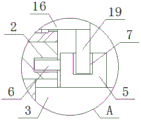
FIG. 2 is a schematic structural diagram of part A of FIG. 1 of the chemical valve according to the present invention;
fig. 3 is a schematic structural diagram of a housing of a chemical valve according to the present invention.
In the figure: the valve comprises a valve body 1, a containing groove 2, a liquid guide pipe 3, a sealing ring 4, a connecting piece 5, a limiting column 6, a fixing groove 7, a shell 8, a sliding rail 9, a square rod 10, a wire shaft 11, a torsion bar 12, a nut 13, a guide slider 14, a guide wheel 15, a solid plate 16, a steel wire rope 17, an air spring 18 and a fixing strip 19.
Detailed Description
The technical solutions in the embodiments of the present invention will be clearly and completely described below with reference to the drawings in the embodiments of the present invention, and it is obvious that the described embodiments are only a part of the embodiments of the present invention, and not all of the embodiments.
Example one
Referring to fig. 1-3, the chemical valve comprises a valve body 1, two holding tanks 2 are arranged on the right side of the valve body 1, a liquid guide pipe 3 is movably inserted into the right side of the valve body 1, a sealing ring 4 positioned in the valve body 1 is fixedly sleeved on the liquid guide pipe 3, the sealing ring 4 is matched with the valve body 1, connecting pieces 5 are fixedly connected to the upper surface and the lower surface of the liquid guide pipe 3, the two connecting pieces 5 are respectively contacted with the right side of the valve body 1, limiting columns 6 are fixedly connected to the left sides of the two connecting pieces 5, the two limiting columns 6 are respectively matched with the two holding tanks 2, fixing grooves 7 are respectively arranged on the sides of the two connecting pieces 5 far away from the liquid guide pipe 3, a shell 8 is fixedly connected to the top and the bottom of the right end of the valve body 1, a slide rail 9 is fixedly connected to one side of the shell 8 close to the valve body 1, and a square rod 10 is fixedly connected between the inner wall of the top and the inner wall of the bottom of the shell 8, the shell 8 is close to one side inner wall of valve body 1 and rotates the one end that is connected with silk axle 11, and outside the other end of silk axle 11 extended to shell 8, and fixedly connected with torsion bar 12, slide rail 9 were located between square bar 10 and the silk axle 11, and threaded sleeve is equipped with nut 13 on the silk axle 11, and silk axle 11 rotates, can drive nut 13 vertical removal.
In the utility model, one side of the nut 13 close to the slide rail 9 is fixedly connected with the guide slide block 14, the guide slide block 14 is slidably mounted on the slide rail 9, and the guide slide block 14 can only vertically slide along the slide rail 9, so that the nut 13 can only vertically move.
In the utility model, two guide wheels 15 are fixedly connected to the inner wall of one side of the shell 8 far away from the valve body 1, and the two guide wheels 15 are positioned between the wire shaft 11 and the square rod 10.
In the utility model, the square bar 10 is slidably sleeved with the solid plate 16, the right end of the solid plate 16 extends out of the shell 8, and the solid plate 16 can only vertically slide along the square bar 10.
In the utility model, one side of the solid plate 16, which is far away from the valve body 1, is fixedly connected with one end of a steel wire rope 17, the other end of the steel wire rope 17 is fixedly connected to the nut 13 through two guide wheels 15, and the nut 13 moves to pull the solid plate 16 through the steel wire rope 17.
According to the utility model, the air spring 18 is movably sleeved on the square rod 10, two ends of the air spring 18 are respectively and fixedly connected to the inner wall of one side of the solid plate 16 far away from the valve body 1 and one side of the outer shell 8, and the elastic restoring force of the air spring 18 can push the solid plate 16 to move.
In the utility model, the fixing strips 19 are fixedly connected to one sides of the two solid plates 16 close to the valve body 1, the two fixing strips 19 are respectively matched with the two fixing grooves 7, and the solid plates 16 move to drive the fixing strips 19 to move, so that the fixing strips 19 are inserted into the fixing grooves 7.
Example two
Referring to fig. 1-3, the chemical valve comprises a valve body 1, two holding tanks 2 are chiseled on the right side of the valve body 1, a liquid guide pipe 3 is movably inserted on the right side of the valve body 1, a sealing ring 4 positioned in the valve body 1 is fixedly sleeved on the liquid guide pipe 3, the sealing ring 4 is matched with the valve body 1, connecting pieces 5 are welded on the upper surface and the lower surface of the liquid guide pipe 3, the two connecting pieces 5 are both contacted with the right side of the valve body 1, limiting columns 6 are welded on the left sides of the two connecting pieces 5, the two limiting columns 6 are respectively matched with the two holding tanks 2, fixing grooves 7 are chiseled on the sides of the two connecting pieces 5 far away from the liquid guide pipe 3, a shell 8 is welded on the top and the bottom of the right end of the valve body 1, a slide rail 9 is welded on the side of the shell 8 close to the valve body 1, and a square rod 10 is welded between the top inner wall and the bottom inner wall of the shell 8, the shell 8 is close to the one side inner wall of valve body 1 and rotates the one end that is connected with silk axle 11, and outside the other end of silk axle 11 extended to shell 8, and the welding had torsion bar 12, and slide rail 9 was located between square bar 10 and the silk axle 11, and threaded sleeve is equipped with nut 13 on the silk axle 11.
In the utility model, a guide sliding block 14 is welded on one side of the nut 13 close to the sliding rail 9, and the guide sliding block 14 is slidably mounted on the sliding rail 9.
In the utility model, two guide wheels 15 are welded on the inner wall of one side of the shell 8 far away from the valve body 1, and the two guide wheels 15 are positioned between the wire shaft 11 and the square rod 10.
In the utility model, a solid plate 16 is slidably sleeved on the square bar 10, and the right end of the solid plate 16 extends out of the shell 8.
In the utility model, one end of a steel wire rope 17 is welded on one side of the solid plate 16, which is far away from the valve body 1, and the other end of the steel wire rope 17 is welded on the nut 13 through two guide wheels 15.
According to the utility model, the air spring 18 is movably sleeved on the square rod 10, and two ends of the air spring 18 are respectively welded on the inner walls of one side of the solid plate 16 far away from the valve body 1 and one side of the outer shell 8.
In the utility model, fixing strips 19 are welded on one sides of the two solid plates 16 close to the valve body 1, and the two fixing strips 19 are respectively matched with the two fixing grooves 7.
In the utility model, during connection, the torsion bar 12 is rotated to rotate the screw shaft 11, the guide slider 14 can only vertically move because the guide slider 14 is slidably mounted on the slide rail 9, so that the nut 13 fixedly connected with the guide slider 14 can only vertically move, the nut 13 is sleeved on the screw shaft 11 in a threaded manner, the nut 13 can be driven to vertically move towards the valve body 1 along with the rotation of the screw shaft 11, the solid plate 16 can only vertically move because the solid plate 16 is slidably sleeved on the square rod 11, and the solid plate 16 can only vertically move because of the connection relationship among the nut 13, the steel wire rope 17 and the solid plate 16, so that the solid plate 16 can be pulled by pulling the steel wire rope 17 along with the movement of the nut 13, the solid plate 16 vertically moves towards the direction far away from the valve body 1 and compresses the air spring 18, and the fixing strip 19 is fixedly connected on the solid plate 16, so that the fixing strip 19 can be driven to move, when the torsion bar 12 can not rotate, the liquid guide tube 3 is inserted into the valve body 1, and the two limiting columns 6 are respectively inserted into the two accommodating grooves 2, when the connecting piece 5 fixedly connected to the liquid guide tube 3 is in contact with the valve body 1, the torsion bar 12 is loosened, the solid plate 16 is pushed to move towards the direction of the valve body 1 due to the elastic restoring force of the air spring 18, so that the fixing strip 19 is driven to move, the fixing strip 19 is inserted into the fixing groove 7, the position of the connecting piece 5 is fixed, and then the connection of the valve body 1 and the liquid guide tube 3 is completed. The valve has the advantages of simple structure, reasonable design and convenient operation, can be quickly installed on the liquid guide pipe, provides convenience for installation personnel, improves the installation efficiency, can be quickly replaced after the valve fails, and is convenient for people to use.
The above description is only for the preferred embodiment of the present invention, but the scope of the present invention is not limited thereto, and any person skilled in the art should be considered to be within the technical scope of the present invention, and equivalent alternatives or modifications according to the technical solution of the present invention and the inventive concept thereof should be covered by the scope of the present invention.
Claims (7)
1. Chemical valve, including valve body (1), its characterized in that, two holding tanks (2) have been seted up on the right side of valve body (1), the right side activity of valve body (1) is pegged graft and is had catheter (3), fixed cover is equipped with sealing washer (4) that are located valve body (1) on catheter (3), and sealing washer (4) and valve body (1) looks adaptation, the upper surface and the lower surface of catheter (3) all fixedly connected with connecting piece (5), and two connecting piece (5) all contact with the right side of valve body (1), the left side of two connecting piece (5) all fixedly connected with spacing post (6), and two spacing post (6) are respectively with two holding tanks (2) looks adaptations, the one side that catheter (3) were kept away from to two connecting piece (5) all seted up fixed slot (7), the top and the bottom of valve body (1) right-hand member all fixedly connected with shell (8), one side fixedly connected with slide rail (9) that shell (8) are close to valve body (1), fixedly connected with square bar (10) between the top inner wall of shell (8) and the bottom inner wall, one side inner wall that shell (8) are close to valve body (1) rotates the one end that is connected with silk axle (11), the other end of silk axle (11) extends to outside shell (8), and fixedly connected with torsion bar (12), slide rail (9) are located between square bar (10) and silk axle (11), threaded sleeve is equipped with nut (13) on silk axle (11).
2. The chemical valve according to claim 1, wherein a guiding sliding block (14) is fixedly connected to one side of the nut (13) close to the sliding rail (9), and the guiding sliding block (14) is slidably mounted on the sliding rail (9).
3. The chemical valve according to claim 1, wherein two guide wheels (15) are fixedly connected to the inner wall of the side of the outer shell (8) far away from the valve body (1), and the two guide wheels (15) are located between the screw shaft (11) and the square rod (10).
4. The chemical valve according to claim 1, characterized in that a solid plate (16) is slidably sleeved on the square rod (10), and the right end of the solid plate (16) extends out of the housing (8).
5. The chemical valve as claimed in claim 4, wherein one side of the solid plate (16) far away from the valve body (1) is fixedly connected with one end of a steel wire rope (17), and the other end of the steel wire rope (17) is fixedly connected to the nut (13) through two guide wheels (15).
6. The chemical valve according to claim 1, wherein the square rod (10) is movably sleeved with an air spring (18), and two ends of the air spring (18) are respectively and fixedly connected to one side of the solid plate (16) far away from the valve body (1) and the inner wall of one side of the outer shell (8).
7. The chemical valve according to claim 4, wherein one side of each of the two solid plates (16) close to the valve body (1) is fixedly connected with a fixing strip (19), and the two fixing strips (19) are respectively matched with the two fixing grooves (7).
Priority Applications (1)
| Application Number | Priority Date | Filing Date | Title |
|---|---|---|---|
| CN202122448910.4U CN216242552U (en) | 2021-10-12 | 2021-10-12 | Chemical valve |
Applications Claiming Priority (1)
| Application Number | Priority Date | Filing Date | Title |
|---|---|---|---|
| CN202122448910.4U CN216242552U (en) | 2021-10-12 | 2021-10-12 | Chemical valve |
Publications (1)
| Publication Number | Publication Date |
|---|---|
| CN216242552U true CN216242552U (en) | 2022-04-08 |
Family
ID=80990148
Family Applications (1)
| Application Number | Title | Priority Date | Filing Date |
|---|---|---|---|
| CN202122448910.4U Expired - Fee Related CN216242552U (en) | 2021-10-12 | 2021-10-12 | Chemical valve |
Country Status (1)
| Country | Link |
|---|---|
| CN (1) | CN216242552U (en) |
-
2021
- 2021-10-12 CN CN202122448910.4U patent/CN216242552U/en not_active Expired - Fee Related
Similar Documents
| Publication | Publication Date | Title |
|---|---|---|
| CN216242552U (en) | Chemical valve | |
| CN120868225B (en) | Ball valve with overpressure emergency self-pressure relief function | |
| CN215371042U (en) | Pressure-resistant gate valve | |
| CN111720595A (en) | Valve for gas pipeline | |
| CN220708811U (en) | Water pollution prevention and treatment sampling device | |
| CN209494013U (en) | A kind of construction of hydro project drainage arrangement | |
| CN215891176U (en) | Gate valve spool assembly and gate valve structure | |
| CN215445089U (en) | Leakage-proof valve device | |
| CN110594481A (en) | Automatic flow control valve | |
| CN210496879U (en) | Automatic spraying machine | |
| CN213298854U (en) | Electric headless butterfly valve | |
| CN210034582U (en) | Circular closed type split regulating valve convenient to adjust | |
| CN210950139U (en) | Emergency manual operation valve | |
| CN216512545U (en) | Crawler crane hood | |
| CN223620175U (en) | A heavy metal ion adsorption and removal device for wastewater based on adsorbent | |
| CN209140555U (en) | A kind of mechanical spool face burr removal device | |
| CN209482994U (en) | A kind of door and window roll wheel assembly facilitating adjusting | |
| CN113983225A (en) | Gate valve capable of being adjusted through automatic transmission based on electric device | |
| CN216813079U (en) | Valve with magnetic adsorption function | |
| CN216618679U (en) | Stop valve with special-shaped valve core and capable of reducing fluid pressure | |
| CN216158422U (en) | Telescopic gate valve based on electric device | |
| CN213271098U (en) | Valve convenient to open and close | |
| CN214838727U (en) | High-performance and high-strength fastening valve body convenient for pressure regulation | |
| CN220891400U (en) | Stainless steel hose joint with anti-backflow function | |
| CN2126696Y (en) | Water turbine type filter |
Legal Events
| Date | Code | Title | Description |
|---|---|---|---|
| GR01 | Patent grant | ||
| GR01 | Patent grant | ||
| CF01 | Termination of patent right due to non-payment of annual fee |
Granted publication date: 20220408 |
|
| CF01 | Termination of patent right due to non-payment of annual fee |