CN2166830Y - escape device - Google Patents
escape device Download PDFInfo
- Publication number
- CN2166830Y CN2166830Y CN 93220736 CN93220736U CN2166830Y CN 2166830 Y CN2166830 Y CN 2166830Y CN 93220736 CN93220736 CN 93220736 CN 93220736 U CN93220736 U CN 93220736U CN 2166830 Y CN2166830 Y CN 2166830Y
- Authority
- CN
- China
- Prior art keywords
- frame
- frame body
- cable wire
- transverse slat
- escape device
- Prior art date
- Legal status (The legal status is an assumption and is not a legal conclusion. Google has not performed a legal analysis and makes no representation as to the accuracy of the status listed.)
- Expired - Fee Related
Links
- 125000006850 spacer group Chemical group 0.000 claims description 4
- 238000000465 moulding Methods 0.000 claims 5
- 238000010276 construction Methods 0.000 claims 2
- PEDCQBHIVMGVHV-UHFFFAOYSA-N Glycerine Chemical compound OCC(O)CO PEDCQBHIVMGVHV-UHFFFAOYSA-N 0.000 claims 1
- 229910000831 Steel Inorganic materials 0.000 description 12
- 239000010959 steel Substances 0.000 description 12
- 238000010586 diagram Methods 0.000 description 8
- 230000037431 insertion Effects 0.000 description 7
- 238000003780 insertion Methods 0.000 description 7
- 230000000694 effects Effects 0.000 description 3
- 230000009286 beneficial effect Effects 0.000 description 1
- 230000009194 climbing Effects 0.000 description 1
- 238000005192 partition Methods 0.000 description 1
- 230000000149 penetrating effect Effects 0.000 description 1
- 238000000926 separation method Methods 0.000 description 1
Images




Landscapes
- Ladders (AREA)
Abstract
Description
本实用新型涉及一种逃生装置,特别是一种用于在危险情况下快速逃离楼房的逃生装置。The utility model relates to an escape device, in particular to an escape device for quickly escaping from a building in a dangerous situation.
一般的防盗是为防止小偷进入室内偷取财物,而在窗户外面加装防盗装置,不单单只限于一层楼的窗子,一般居住于二楼以上的居户,依然会在其窗子外面加装防盗装置,以防止小偷进入。The general anti-theft is to prevent thieves from entering the room to steal property, and install anti-theft devices on the outside of the windows, not only limited to the windows on the first floor, but generally residents living on the second floor or above will still install the anti-theft devices on the outside of their windows. Anti-theft device to prevent thieves from entering.
虽然防盗装置具有防盗作用,在现今居住房屋皆存有易于燃烧的物品情形下,常会因电器用品使用不当,或小孩玩耍打火机(或火柴),或煤气外泄,或其它因素,造成房屋失火时,防盗装置反而成为阻碍逃生的设置,此在报章杂志上,时有所闻,另外,即使没有设置防盗装置,在位于无法跳至地面以上的楼层时,一般窗子或防盗窗又没有可供逃生的设备,故,一旦发生火警时,人们也只能在生死边缘之际,等待消防人员的救助。Although the anti-theft device has the function of anti-theft, in the situation that there are flammable items in the living houses today, it is often caused by improper use of electrical appliances, or children playing with lighters (or matches), or gas leakage, or other factors, causing the house to catch fire. However, the anti-theft device has instead become a setting that hinders escape. This is often heard in newspapers and magazines. In addition, even if no anti-theft device is installed, when the floor is located where it is impossible to jump above the ground, there is no general window or anti-theft window for escape. Therefore, in the event of a fire, people can only wait for the rescue of firefighters when they are on the verge of life and death.
本实用新型的目的在于提供一种逃生装置,其是在发生火警时,作为能够快速逃生的工具。The purpose of the utility model is to provide an escape device, which is used as a tool for rapid escape in case of fire.
本实用新型的逃生装置包括内框体及绳梯,绳梯容置在内框体内,绳梯上设有定位装置,内框体上设有定位部,所述绳梯包括有横板与设有横板两端的钢索,所述定位装置设在钢索上,绳梯与内框体之间藉由定位部与定位装置,呈可拆卸地相互枢接。The escape device of the present utility model includes an inner frame body and a rope ladder. The rope ladder is accommodated in the inner frame body. A positioning device is provided on the rope ladder, and a positioning part is provided on the inner frame body. The steel cable at the end, the positioning device is arranged on the steel cable, and the rope ladder and the inner frame are detachably pivoted to each other through the positioning part and the positioning device.
此外,本实用新型的逃生装置还可设置外框体,外框体底端则藉由二合页,以与内框体底端呈枢接状态,且外框体顶端设有二个卡止元件,以使外框体与内框体卡结一起,如此,当操作卡止元件,以使内、外框体分离,且外框体即能向下旋转,而使绳梯快速地从内框体自动脱离,以供逃生用。In addition, the escape device of the present utility model can also be provided with an outer frame, and the bottom of the outer frame is hinged with the bottom of the inner frame by means of two hinges, and the top of the outer frame is provided with two latches. Components, so that the outer frame and the inner frame are locked together, so that when the locking element is operated, the inner and outer frames are separated, and the outer frame can be rotated downward, so that the rope ladder can quickly move from the inner frame The body is automatically detached for escape.
本实用新型的效果:使用本逃生装置,在危险情况下,即能马上从高层建筑中逃出火灾或其他危险现场,而确保生命安全,本装置便于收合及快速打开。Effects of the utility model: the escape device can immediately escape from a high-rise building in a fire or other dangerous scene in a dangerous situation, thereby ensuring life safety. The device is convenient for folding and opening quickly.
下面通过最佳实施例及附图对本实用新型的逃生装置进行详细说明,附图中:The escape device of the present utility model is described in detail below through the preferred embodiment and the accompanying drawings, in the accompanying drawings:
图1是本实用新型较佳实施例逃生装置立体示意图。Fig. 1 is a three-dimensional schematic diagram of an escape device according to a preferred embodiment of the present invention.
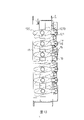
图2是图1的AA剖视图。FIG. 2 is an AA sectional view of FIG. 1 .
图3是图1的BB剖视图。Fig. 3 is a BB sectional view of Fig. 1 .
图4、5是本实用新型实施例内框体的上(下)框、左(右)框断面示意图。Figures 4 and 5 are schematic cross-sectional views of the upper (lower) frame and the left (right) frame of the inner frame of the embodiment of the present invention.
图6、7是本实用新型实施例外框体的上(下)框条、左(右)框条断面示意图。Figures 6 and 7 are schematic cross-sectional views of the upper (lower) frame and left (right) frame of the outer frame of the embodiment of the utility model.
图8是本实用新型较佳实施例绳梯组合示意图。Fig. 8 is a schematic diagram of a combination of rope ladders in a preferred embodiment of the present invention.
图9是本实用新型较佳实施例卡止元件与内框体的上框卡合示意图。Fig. 9 is a schematic diagram of the locking element and the upper frame of the inner frame in a preferred embodiment of the present invention.
图10是本实用新型较佳实施例逃生装置使用展开示意图。Fig. 10 is a schematic diagram showing the deployment of the escape device according to the preferred embodiment of the present invention.
图11是本实用新型较佳实施例逃生装置装设于窗子供逃生的示意图。Fig. 11 is a schematic diagram of an escape device installed on a window for escape in a preferred embodiment of the present invention.
图12是本实用新型另一个较佳实施例逃生装置内框体的左框与横板分解立体图。Fig. 12 is an exploded perspective view of the left frame and the horizontal plate of the inner frame of the escape device in another preferred embodiment of the present invention.
图13是本实用新型另一个较佳实施例逃生装置横板与导板动作示意图。Fig. 13 is a schematic diagram of the action of the horizontal plate and the guide plate of the escape device in another preferred embodiment of the present invention.
图14是本实用新型另一个较佳实施例的分解示意图。Fig. 14 is an exploded schematic view of another preferred embodiment of the present invention.
图15是本实用新型另一个较佳实施例的组合示意图。Fig. 15 is a combined schematic diagram of another preferred embodiment of the present invention.
如图1所示,是本实用新型较佳实施例逃生装置立体示意图,配合图2、3所示,逃生装置1大体上是由内框体10及绳梯12所构成。As shown in FIG. 1 , it is a three-dimensional schematic view of an escape device according to a preferred embodiment of the present invention. As shown in FIGS. 2 and 3 , the
如图10所示,其是本实用新型一较佳实施例,其除了包括有绳梯12、内框体10之外,还设置有外框体11。As shown in FIG. 10 , it is a preferred embodiment of the present invention, and besides a
内框体10是由一上框100、一下框101、一左框102及一右框103组合而成,上框100与下框101结构相同,如图4所示,两断面呈
状,左框102与右框103分别螺固在上框100与下框101的左右端之间,如图5所示,左框102与右框103结构也相同,在其内部设有定位部,所述定位部是容室1020、1030,并于容室1020、1030同侧设有一卡置部1021、1031,且于容室1020、1030外侧设有一约呈倒L形的挡止部1022、1032。The
外框体11枢置在内框体10外面,其也是由上框条110、一下框条111、左框条112及右框条113组合而成,如图6所示,上框条110与下框条111结构相同,两断面呈口状,左框条112与右框条113分别螺固于上框条110与下框条111的左右端,如图7所示,左框条112与右框条113结构也相同,并在左右框条112、113分别相对于左右框102、103的卡置部1021、1031,其设有一约呈口状的中空部1120、1130,而另一相对应于挡止部1022、1032则设有一约呈L状的挡板1121、1131;在下框条111底端面预定处固设有二合页13,且二合页13也固设在内框体10的下框101上,以使外框体11与内框体10呈枢接状态,此外,如图8所示,邻近于上框体110内侧面两端设有二直立卡止元件14,以使外框体11与内框体10枢接一起,卡止元件14是由一座体140与一插杆141组成,座体140设有一透空状的通道1400,以供插杆141枢置,并于通道1400顶、底端各设有一缺口1401,且在插杆141上面设有一把手1410,以供控制插杆141动作。The
绳梯12枢置于内框体10左右框102、103的挡止部1022、1032与外框体11左、右框条112、113的挡板1121、1131内,以供逃生时攀爬之用,如图9所示,绳体12是由预定数目的横板120与两分别穿置横板120两端的钢索121所组成,横板120两端皆分别固设一呈圆状的圆板123,以使壁面与圆板123之间形成间隙,而利于逃生用(如图11所示),且圆板123容置于内框体10左右框102、103的挡止部1022、1032与外框体11左、右框条112、113的挡板1121、1131内,两钢索121顶端分别设有一定位装置,所述定位装置是挡块124,而两挡块124则又分别枢置于内框体10左右框102、103的容室1020、1030内,且钢索121穿过横板120时,在横板120上下处的钢索121表面各卷固有一限制片125,以使横板120可分别定位于钢索121上。The
关于本实用新型组合情形,是将上框100、下框101、左框102及右框103组合完成内框体10,且上框条110、下框条111、左框条112及右框条113组合完成外框体11,并于下框条111底端面螺设二合页13,以及在上框条110螺设二卡止元件14,然后,再将二合页13螺设在内框体10的下框101,以使内框体10与外框体11形成枢接状态,最后,将绳梯12置于内框体10内之后,即将外框体11覆盖于内框体10外面,并藉由卡止元件14的插杆141插入上框100顶端预定处,即能组成如图1所示的完成品。Regarding the combined situation of the present utility model, the
如图10所示,当操作二卡止元件14插杆141的把手1410,以使插杆141脱离上框100时,内框体10与外框体11便形成可旋转分离状态,所以,当对外框体11顶端施予力量,外框体11便以二合页13为旋转中心,然后向下旋转,而原本受到左右框102、103的挡止部1022、1032与左右框条112、113的挡板1121、1131定位夹住的绳梯12的横板120,便因外框体11已与内框体10不再结合一起,而在不受定位限制之下,即会自动随外框体11向下旋转而倒向内框体10外面下方,如图11所示,当逃生装置1装设于楼房3的窗户30外面时,只要火灾一发生,人们便可依照上述操作方式,而将绳梯12马上向上延展开,以供人们迅速逃生。As shown in Figure 10, when the
如图12所法,是本实用新型另一个较佳实施例逃生装置内框体的左框与横板分解示意图,本实施例的结构,大体上与上述实施例相同,其不同之处在于:横板120断面是呈橄榄状,并于两端各设有一锁固部1200、1201,以供各套置一概呈方形的隔板126,且于横板120一端固设有一勾片127,勾片127末端设有一月儿口1270,而配合勾片127,于内框体10的左框102的挡止部1022外侧面,其设有一断面呈
状的导引槽104,以供一导板15套置,于导板15表面设有一牵动部150,并于牵动部150表面等间隔贯设有预定数目的插孔151,插孔151数目是依照横板120数目而定,且每一插孔151分别插置一插销16,插销16并位于月儿口1270内,然后藉由一弹性夹17,以使插销16与勾片127结合一起;如此,如图13所示,当使用者的手握住导板15,然后,带动导板15向上移动,即能藉由插销16牵动勾片127,以使横板120向上转动,以达到遮阳效果,使得本实用新型除了具有防盗、逃生作用之外,又具有遮阳功效。As shown in Figure 12, it is an exploded schematic diagram of the left frame and the horizontal plate of the inner frame of the escape device in another preferred embodiment of the present invention. The structure of this embodiment is generally the same as that of the above embodiment, and the difference lies in: The cross-section of the
最后,如图14所示,其是本实用新型又一个较佳实施例的逃生装置,其与前述二实施例最大不同的是:本实施例是可移动式的,其呈一箱体状,包括一内框体20及一绳梯30,内框体20由一下框21,及垂立在下框21两端的一左框22、右框23,与一可掀开、盖合在左框22、右框23上端的上框24组成,左、右框的构造相同(以下仅就右框加以说明),左框22、右框23具有
形断面,其开口相对应,上框24穿枢在左框22上缘处,上框24邻接右框23的一端设有一扣耳240,在右框23上缘设设有一定位部,其是扣钩230,扣钩230可与扣耳240扣合,而使上框24与左框22、右框23形成闭锁状,在下框21上及左框22、右框23之间是用来容纳绳梯30,绳梯30由一根根的横板31以钢索32串接起来,是在横板31的两端固定一间隔块310,在间隔块310上再以钢索一端所设的套环320穿套,最后以一套盖311封闭横板31的管端,而整个绳梯30的源端,是以钢索32穿过左框22、右框23邻近下框21所设的一穿孔200,再穿结一定位装置,定位装置是一安全扣33,使用时,将钢索32缠绑在固定物上,并以安全扣33的扣环330钩扣钢索32,然后打开上框24将绳梯30从内框体20内取出并丢出窗口,如此,便可踩着横板31顺降逃生(如图11所示),而在未使用状态时,则将绳梯30有秩序的堆叠在内框体20内,如图15所示,并以上框24上所设的把手241方便提拿,且置放在明显、便于拿取的位置。Finally, as shown in Figure 14, it is another preferred embodiment of the escape device of the present invention. The biggest difference from the previous two embodiments is that this embodiment is movable, and it is in the shape of a box. Including an
Claims (7)
Priority Applications (1)
| Application Number | Priority Date | Filing Date | Title |
|---|---|---|---|
| CN 93220736 CN2166830Y (en) | 1993-08-16 | 1993-08-16 | escape device |
Applications Claiming Priority (1)
| Application Number | Priority Date | Filing Date | Title |
|---|---|---|---|
| CN 93220736 CN2166830Y (en) | 1993-08-16 | 1993-08-16 | escape device |
Publications (1)
| Publication Number | Publication Date |
|---|---|
| CN2166830Y true CN2166830Y (en) | 1994-06-01 |
Family
ID=33799797
Family Applications (1)
| Application Number | Title | Priority Date | Filing Date |
|---|---|---|---|
| CN 93220736 Expired - Fee Related CN2166830Y (en) | 1993-08-16 | 1993-08-16 | escape device |
Country Status (1)
| Country | Link |
|---|---|
| CN (1) | CN2166830Y (en) |
-
1993
- 1993-08-16 CN CN 93220736 patent/CN2166830Y/en not_active Expired - Fee Related
Similar Documents
| Publication | Publication Date | Title |
|---|---|---|
| US20080116007A1 (en) | Stowable, unobtrusive access and escape devices | |
| US4445589A (en) | Window assembly including a storable fire escape | |
| CA2601483C (en) | Method and apparatus for window covering with a cord safety device | |
| KR101131484B1 (en) | Escaping apparatus for emergency evacuation | |
| US5372217A (en) | Emergency escape device | |
| KR101171248B1 (en) | An apparatus for escaping from fire in the high building | |
| KR101171249B1 (en) | An apparatus for escaping from fire in the high building | |
| WO1996032564A1 (en) | Emergency escape ladder assembly | |
| CN2420021Y (en) | Super high building fire safety escape combination device | |
| CN103781984A (en) | Fall prevention apparatus for a window | |
| US20120228057A1 (en) | Hidden fire escape ladder system with spring-loaded standoffs | |
| JPH11256968A (en) | Flat roof ladder | |
| KR20110000780A (en) | Shutter Safety Railings for Fire Evacuation | |
| JP3474641B2 (en) | shutter | |
| CN214512300U (en) | An extrapolation type high-rise fire escape device | |
| JP2000325489A (en) | Grid-type evacuation ladder | |
| KR200464791Y1 (en) | The safety ladder | |
| JP3234934B2 (en) | Evacuation device | |
| WO1990003487A1 (en) | Arrangement in fire escape ladder | |
| KR102528446B1 (en) | The Parapet of an apartment building for easy assembly | |
| KR101070794B1 (en) | A Rescue Ladder Which Has a Pulling Wire | |
| JP2949463B2 (en) | Folding ladder | |
| JPS6242039Y2 (en) | ||
| JP2509606Y2 (en) | Emergency ladder equipment in a building | |
| JPS5942047Y2 (en) | Rescue bag tension device |
Legal Events
| Date | Code | Title | Description |
|---|---|---|---|
| C14 | Grant of patent or utility model | ||
| GR01 | Patent grant | ||
| C19 | Lapse of patent right due to non-payment of the annual fee | ||
| CF01 | Termination of patent right due to non-payment of annual fee |