CN216802443U - Robot electric arc increases and decreases material system - Google Patents

Robot electric arc increases and decreases material system Download PDF

Info

Publication number
CN216802443U
CN216802443U CN202220134167.7U CN202220134167U CN216802443U CN 216802443 U CN216802443 U CN 216802443U CN 202220134167 U CN202220134167 U CN 202220134167U CN 216802443 U CN216802443 U CN 216802443U
Authority
CN
China
Prior art keywords
mounting seat
material system
turning
positioner
fixed
Prior art date
Legal status (The legal status is an assumption and is not a legal conclusion. Google has not performed a legal analysis and makes no representation as to the accuracy of the status listed.)
Active
Application number
CN202220134167.7U
Other languages
Chinese (zh)
Inventor
程远
袁玉荣
蔡朋飞
Current Assignee (The listed assignees may be inaccurate. Google has not performed a legal analysis and makes no representation or warranty as to the accuracy of the list.)
Nanjing Yingnigema Industrial Automation Technology Co Ltd
Original Assignee
Nanjing Yingnigema Industrial Automation Technology Co Ltd
Priority date (The priority date is an assumption and is not a legal conclusion. Google has not performed a legal analysis and makes no representation as to the accuracy of the date listed.)
Filing date
Publication date
Application filed by Nanjing Yingnigema Industrial Automation Technology Co Ltd filed Critical Nanjing Yingnigema Industrial Automation Technology Co Ltd
Priority to CN202220134167.7U priority Critical patent/CN216802443U/en
Application granted granted Critical
Publication of CN216802443U publication Critical patent/CN216802443U/en
Active legal-status Critical Current
Anticipated expiration legal-status Critical

Links

Images

Landscapes

  • Manipulator (AREA)

Abstract

本实用新型公开了一种机器人电弧增减材系统,包括并行设置的地轨以及架设在地轨上的铣削机构,还包括设置在地轨上相对地轨水平向移动的焊接机器人;在并行设置的地轨结构之间设有变位机,变位机具有翻转机构、旋转机构和升降机构;变位机的转接板上固定有柔性工作台。本实用新型系统基于多功能变位机,可以实现大型或异形件进行增材制造,系统中在含有焊接机器人的同时含有铣削机构,因此可以在增材一部分后立即对增材部分进行铣削操作,从而提高成品的加工精度,并且在全部打印完成后,手持蓝光测量仪对粗成品进行扫描,扫描后再利用铣削机构对粗成品进行铣削,得到精加工成品。

Figure 202220134167

The utility model discloses a robot arc adding and subtracting material system, which comprises ground rails arranged in parallel and a milling mechanism erected on the ground rails, and also comprises a welding robot arranged on the ground rails to move horizontally relative to the ground rails; A positioner is arranged between the ground rail structures of the positioner, and the positioner has a turning mechanism, a rotating mechanism and a lifting mechanism; a flexible worktable is fixed on the adapter plate of the positioner. The system of the utility model is based on a multi-function positioner, which can realize the additive manufacturing of large or special-shaped parts. The system includes a welding robot and a milling mechanism, so that the milling operation can be performed on the additive part immediately after adding a part, Thereby, the machining accuracy of the finished product is improved, and after all the printing is completed, the rough product is scanned with a handheld blue light measuring instrument, and then the rough product is milled by a milling mechanism to obtain a finished product after scanning.

Figure 202220134167

Description

Robot electric arc increases and decreases material system
Technical Field
The utility model relates to a robot arc material increase and decrease system.
Background
Based on some specific scenes or the requirements of finish machining, a part needs to be subjected to a milling operation after the part is subjected to additive manufacturing in a 3D printing (additive manufacturing) process, so that the machining precision of a finished product is improved.
SUMMERY OF THE UTILITY MODEL
Utility model purpose: the utility model aims to provide a robot arc material increase and decrease system which can realize three manufacturing processes of welding, metal fuse arc material increase (3D printing) and material decrease.
The technical scheme is as follows: the utility model relates to a robot electric arc material increase and decrease system, which comprises a ground rail arranged in parallel, a milling mechanism erected on the ground rail and a welding robot arranged on the ground rail and moving horizontally relative to the ground rail; a position changing machine is arranged between the ground rails which are arranged in parallel, and the position changing machine is provided with a turnover mechanism, a rotating mechanism and a lifting mechanism; a flexible workbench is fixed on the adapter plate of the positioner.
The ground rail comprises a base, a guide rail fixed on the base, and a transmission mechanism used for driving the welding robot and the milling mechanism to transversely move on the ground rail, wherein the transmission mechanism is a gear and rack transmission mechanism or a transmission mechanism in matched connection of a ball screw and a nut.
The milling mechanism comprises a Z axis, an X axis moving mechanism and a Z axis moving mechanism, a milling cutter and a laser vision camera are arranged at the end part of the Z axis, and the Z axis moves along the X axis direction and the Z axis direction respectively in the X axis moving mechanism and the Z axis moving mechanism.
Wherein, the welding robot includes six moving arms and is located the welder of six moving arm tip.
The rotary mechanism comprises a rotary motor, an adapter plate fixedly connected with a drive shaft of the rotary motor through a slewing bearing, and a flexible workbench fixed on the adapter plate.
The turnover mechanism comprises a first mounting seat, a second mounting seat and a turnover table positioned between the first mounting seat and the second mounting seat; the rotating mechanism is rotationally connected with the overturning platform through a slewing bearing; the turnover mechanism further comprises a turnover motor fixed on the first mounting seat, a drive end of the turnover motor is fixedly connected with the speed reducer, the drive end of the speed reducer is fixedly connected with one side of the turnover table through a rotating shaft, the other side of the turnover table is fixedly connected with the second mounting seat through a driven rotating shaft, and the driven rotating shaft is rotatably connected with the second mounting seat through a bearing.
The lifting mechanism comprises an upright post, and two parallel guide rails are arranged on two opposite side edges of the upright post; the lifting mechanism also comprises a motor and a ball screw in transmission connection with the motor; two end parts of the ball screw are fixed on the upright post through a bearing seat, and a screw nut which is matched and connected with the ball screw is sleeved on the ball screw; the first mounting seat and the second mounting seat of the turnover mechanism are fixedly connected with the corresponding lead screw nuts, and the first mounting seat and the second mounting seat are further provided with sliding blocks which are connected with the guide rails in a matched mode.
Has the advantages that: the system disclosed by the utility model is based on a multifunctional positioner, additive manufacturing of large or special-shaped parts can be realized, the system contains a welding robot and a milling mechanism, so that the additive part can be milled immediately after a part of additive is added, the machining precision of finished products is improved, and after all printing is finished, a blue light measuring instrument is held by hand to scan the rough finished products, and the rough finished products are milled by the milling mechanism after scanning, so that finished products are obtained.
Drawings
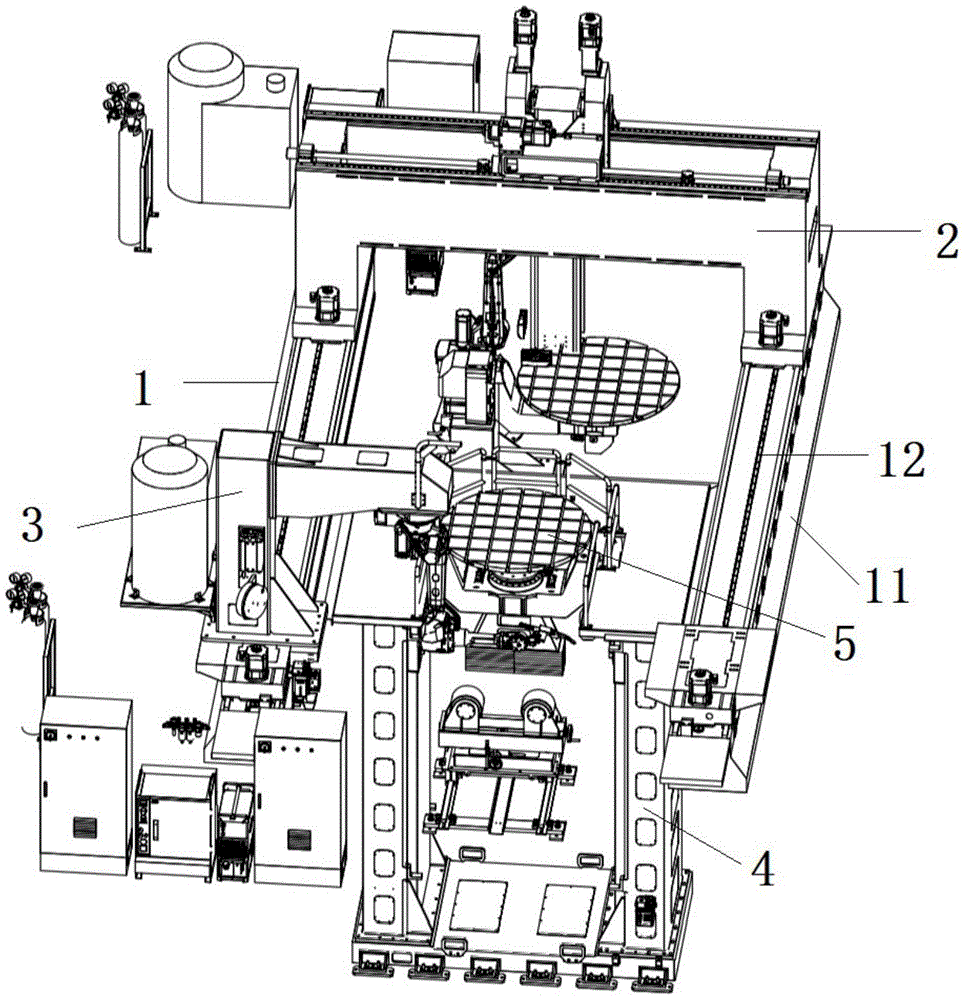
FIG. 1 is a system schematic diagram of a robot arc material adding and removing system of the present invention;
FIG. 2 is a schematic structural diagram of a milling mechanism;
FIG. 3 is a schematic structural diagram of the positioner;
FIG. 4 is a schematic structural view of a rotating mechanism in the positioner;
FIG. 5 is a schematic structural diagram of a turnover mechanism in the positioner;
FIG. 6 is a schematic view of the connection between the mounting plate and the lifting mechanism in the turnover mechanism;
fig. 7 is a schematic structural view of a lifting mechanism in the positioner.
Detailed Description
As shown in fig. 1 to 7, the robot arc material-increasing and material-decreasing system of the present invention comprises a ground rail 1 arranged in parallel, a milling mechanism 2 erected on the ground rail 1, and a welding robot 3 arranged on the ground rail 1 and moving horizontally relative to the ground rail 1; a position changing machine 4 is arranged between the ground rails 1 which are arranged in parallel, and the position changing machine 4 is provided with a turnover mechanism, a rotating mechanism and a lifting mechanism; a flexible workbench 5 is fixed on the adapter plate of the positioner 4; the milling mechanism 2 comprises a Z-axis 21, an X-axis moving mechanism 22 and a Z-axis moving mechanism, a milling cutter 24 and a laser vision camera 23 are arranged at the end part of the Z-axis 21, and the Z-axis 21 moves along the X-axis direction and the Z-axis direction respectively in the X-axis moving mechanism 22 and the Z-axis moving mechanism; the welding robot 3 includes a six-axis moving arm and a welding gun located at an end of the six-axis moving arm.
The ground rail 1 comprises a base 11, a guide rail 12 fixed on the base 11, and a transmission mechanism for driving the welding robot 3 and the milling mechanism 2 to move transversely on the guide rail 12, wherein the transmission mechanism is a gear-rack transmission mechanism or a transmission mechanism in matched connection of a ball screw and a nut.
The rotating mechanism of the positioner 4 includes a rotating motor 41, an adapter plate 43 fixedly connected to a drive shaft of the rotating motor 41 via a slewing bearing 42, and a flexible table 5 fixed to the adapter plate 43. The turnover mechanism comprises a first mounting seat 44, a second mounting seat 45 and a turnover table 46 positioned between the first mounting seat 44 and the second mounting seat 45; the rotating mechanism is rotationally connected with the overturning platform 46 through a slewing bearing 42; the turnover mechanism further comprises a turnover motor 47 fixed on the first installation base 44, a driving end of the turnover motor 47 is fixedly connected with one side of the turnover table 46 through a rotating shaft 49, the other side of the turnover table 46 is fixedly connected with the second installation base 45 through a driven rotating shaft 50, and the rotating shaft 49 and the driven rotating shaft 50 are respectively connected with the first installation base 44 and the second installation base 45 through bearings in a rotating mode. The bottom of the overturning platform 46 is also provided with a weight box 51; the two sides of the overturning platform 46 corresponding to the joint of the slewing bearing 42 are also provided with conductive seats 52, and the conductive seats 52 are used for grounding, so that strong current or redundant current generated in the operation of equipment is led into the ground, and the safety is ensured; the turnover mechanism further comprises a brake, the brake comprises a clamp 54 with a notch and a rotary disc 53 rotating in the notch of the clamp 54, the rotary disc 53 is fixed at the end part of the turnover table 46 and rotates together with the turnover table 46, the clamp 54 is fixed on the second mounting seat 45, and when the turnover table 46 is turned over, the rotary disc 53 and the clamp 54 generate friction force to enable the turnover to be stably carried out. The lifting mechanism comprises a vertical column 55, and two parallel guide rails 56 are arranged on two opposite side edges of the vertical column 55; the lifting mechanism also comprises a motor 58, the motor 58 is in transmission connection with a ball screw 61 through a speed reducer 59 and a coupling 60; two end parts of the ball screw 61 are fixed on the upright post 55 through bearing seats 62, and a screw nut 63 which is matched and connected with the ball screw 61 is sleeved on the ball screw 61; the upright column 55 of the lifting mechanism is not less than 2m and is paved under the ground. The first installation seat 44 and the second installation seat 45 of the turnover mechanism are fixedly connected with the corresponding lead screw nuts 63, and the first installation seat 44 and the second installation seat 45 are further provided with sliding blocks 57 which are connected with the guide rails in a matched mode.

Claims (8)

1.一种机器人电弧增减材系统,其特征在于:包括并行设置的地轨以及架设在地轨上的铣削机构,还包括设置在地轨上相对地轨水平向移动的焊接机器人;在并行设置的地轨结构之间设有变位机,变位机具有翻转机构、旋转机构和升降机构;变位机的转接板上固定有柔性工作台。1. A robotic arc adding and subtracting material system, is characterized in that: comprise the ground rail that is arranged in parallel and the milling mechanism that is erected on the ground rail, also comprise the welding robot that is arranged on the ground rail to move horizontally relative to the ground rail; A positioner is arranged between the arranged ground rail structures, and the positioner has a turning mechanism, a rotating mechanism and a lifting mechanism; a flexible worktable is fixed on the adapter plate of the positioner. 2.根据权利要求1所述的机器人电弧增减材系统,其特征在于:所述地轨包括底座、固定在底座上的导轨以及用于驱动焊接机器人和用于驱动铣削机构在导轨上横向移动的传动机构。2 . The robotic arc adding and subtracting material system according to claim 1 , wherein the ground rail comprises a base, a guide rail fixed on the base, and a guide rail for driving the welding robot and for driving the milling mechanism to move laterally on the guide rail. 3 . transmission mechanism. 3.根据权利要求1所述的机器人电弧增减材系统,其特征在于:所述铣削机构包括Z轴、X轴移动机构和Z轴移动机构,在Z轴端部设有铣削刀具和激光视觉相机,Z轴在X轴移动机构和Z轴移动机构分别沿X轴方向移动和Z轴方向移动。3. The robotic arc adding and subtracting material system according to claim 1, wherein the milling mechanism comprises a Z-axis, an X-axis moving mechanism and a Z-axis moving mechanism, and a milling tool and a laser vision are provided at the end of the Z-axis For the camera, the Z-axis is moved in the X-axis direction and the Z-axis moving mechanism is moved in the X-axis direction and the Z-axis direction, respectively. 4.根据权利要求1所述的机器人电弧增减材系统,其特征在于:所述焊接机器人包括六轴移动臂以及位于六轴移动臂端部的焊枪。4 . The robotic arc adding and subtracting material system according to claim 1 , wherein the welding robot comprises a six-axis moving arm and a welding torch located at the end of the six-axis moving arm. 5 . 5.根据权利要求1所述的机器人电弧增减材系统,其特征在于:所述旋转机构包括旋转电机、与旋转电机驱动轴通过回转支承轴承固定连接的转接板以及固定在转接板上的柔性工作台。5 . The robotic arc adding and subtracting material system according to claim 1 , wherein the rotating mechanism comprises a rotating motor, an adapter plate fixedly connected with the drive shaft of the rotating motor through a slewing bearing, and a adapter plate fixed on the adapter plate. 6 . flexible workbench. 6.根据权利要求1所述的机器人电弧增减材系统,其特征在于:所述翻转机构包括第一安装座、第二安装座以及位于第一安装座和第二安装座之间的翻转台;旋转机构通过回转支承轴承与翻转台转动连接;所述翻转机构还包括固定在第一安装座上的翻转电机、翻转电机的驱动端与减速机固定连接,减速机的驱动端通过旋转轴与翻转台的一侧固定连接,翻转台的另一侧通过从动旋转轴与第二安装座固定连接,从动旋转轴与第二安装座通过轴承转动连接。6 . The robotic arc adding and subtracting material system according to claim 1 , wherein the turning mechanism comprises a first mounting seat, a second mounting seat, and a turning table between the first mounting seat and the second mounting seat. 7 . The rotating mechanism is rotatably connected with the turning table through the slewing support bearing; the turning mechanism also includes a turning motor fixed on the first mounting seat, the driving end of the turning motor is fixedly connected with the reducer, and the driving end of the reducer is connected to the reducer through the rotating shaft. One side of the overturning table is fixedly connected, and the other side of the overturning table is fixedly connected with the second mounting seat through a driven rotating shaft, and the driven rotating shaft and the second mounting seat are rotatably connected through a bearing. 7.根据权利要求6所述的机器人电弧增减材系统,其特征在于:所述翻转机构还包括刹车器,刹车器包括带槽口的钳以及在钳的槽口中转动的转盘,转盘固定在翻转台端部与翻转台一起转动,钳固定在第二安装座上。7. The robotic arc adding and subtracting material system according to claim 6, wherein the turning mechanism further comprises a brake, and the brake comprises a tong with a slot and a turntable rotating in the slot of the tong, and the turntable is fixed on the The end of the turning table rotates together with the turning table, and the clamp is fixed on the second mounting seat. 8.根据权利要求1所述的机器人电弧增减材系统,其特征在于:所述升降机构包括立柱,在立柱相对两个侧边设有两个并行的导轨;升降机构还包括电机以及与电机传动连接的滚珠丝杆;滚珠丝杆两个端部均通过轴承座固定在立柱上,滚珠丝杆上套有与之配合连接的丝杆螺母;翻转机构的第一安装座和第二安装座均与对应的丝杆螺母固定连接,第一安装座和第二安装座还设有与导轨配合连接的滑块。8 . The robotic arc adding and subtracting material system according to claim 1 , wherein the lifting mechanism comprises a column, and two parallel guide rails are arranged on opposite sides of the column; the lifting mechanism further comprises a motor and a motor connected to the motor. 9 . The ball screw connected by the transmission; the two ends of the ball screw are fixed on the column through the bearing seat, and the ball screw is sleeved with a screw nut that is connected with it; the first mounting seat and the second mounting seat of the turning mechanism Both are fixedly connected with the corresponding screw nuts, and the first mounting seat and the second mounting seat are also provided with sliding blocks which are matched and connected with the guide rails.
CN202220134167.7U 2022-01-19 2022-01-19 Robot electric arc increases and decreases material system Active CN216802443U (en)

Priority Applications (1)

Application Number Priority Date Filing Date Title
CN202220134167.7U CN216802443U (en) 2022-01-19 2022-01-19 Robot electric arc increases and decreases material system

Applications Claiming Priority (1)

Application Number Priority Date Filing Date Title
CN202220134167.7U CN216802443U (en) 2022-01-19 2022-01-19 Robot electric arc increases and decreases material system

Publications (1)

Publication Number Publication Date
CN216802443U true CN216802443U (en) 2022-06-24

Family

ID=82064021

Family Applications (1)

Application Number Title Priority Date Filing Date
CN202220134167.7U Active CN216802443U (en) 2022-01-19 2022-01-19 Robot electric arc increases and decreases material system

Country Status (1)

Country Link
CN (1) CN216802443U (en)

Cited By (1)

* Cited by examiner, † Cited by third party
Publication number Priority date Publication date Assignee Title
CN116618840A (en) * 2023-06-28 2023-08-22 吉林省力科科技有限公司 Combined robot and gantry dual-station laser additive and subtractive material manufacturing and repair system

Cited By (1)

* Cited by examiner, † Cited by third party
Publication number Priority date Publication date Assignee Title
CN116618840A (en) * 2023-06-28 2023-08-22 吉林省力科科技有限公司 Combined robot and gantry dual-station laser additive and subtractive material manufacturing and repair system

Similar Documents

Publication Publication Date Title
CN113664416B (en) Automatic welding machine and welding method for steel structural members
CN101456182B (en) Large workpiece welding intelligent robot device
CN112518773A (en) A multi-functional industrial robot for intelligent manufacturing
CN210314488U (en) Laser cladding equipment
CN115741102B (en) An automatic clamping gantry type friction stir welding defect repair equipment
CN113681309B (en) Mobile milling machine system and hole system processing method
CN106238995A (en) Utilize the welding method of shot-blasting machine case weld machine people's assembly
CN216802443U (en) Robot electric arc increases and decreases material system
CN112548583A (en) Marine propeller machining robot and machining method thereof
CN106238994B (en) Shot blasting machine shell welding robot assembly
CN113070874A (en) Automatic navigation multifunctional operation robot based on three-dimensional reconstruction
CN205464817U (en) Three -dimensional welding machine
CN118663961B (en) Intelligent milling machine and method for machining mechanical parts
CN118321813A (en) Series-parallel welding robot for narrow space operation
CN108788577A (en) A kind of large tank robot automation welding workstation
CN216829243U (en) A multi-angle processing laser cutting equipment
CN215942330U (en) Robot system for machining hole series of large-size steel plate
CN118342292A (en) Turnover plate horizontal machining center workbench turnover exchange mechanism
CN116572065A (en) A compound processing machine tool for adding and subtracting materials
CN114799842A (en) Optical-mechanical module combined assembly system
CN117324854A (en) Stainless steel welding equipment based on positioning and clamping
CN214134324U (en) A toothed workpiece rotary positioner and toothed workpiece processing equipment
CN201979217U (en) Rotary worktable for laser welding
CN110814627B (en) Be used for robot welded platform
CN223198359U (en) A crawling trolley multi-layer and multi-pass automatic welding equipment for circumferential and longitudinal seams

Legal Events

Date Code Title Description
GR01 Patent grant
GR01 Patent grant