Groove type that animal remedy production used mixes quick-witted feed additive production facility
Technical Field
The utility model relates to the technical field of feed processing, in particular to groove-shaped mixing machine feed additive production equipment for veterinary drug production.
Background
The feed additive is a small amount or trace substance added in the production, processing and using processes of feed, the dosage of the feed additive is small but the effect is obvious, the feed additive is a raw material inevitably used in modern feed industry, and the feed additive has obvious effects on enhancing the nutritive value of basic feed, improving the production performance of animals, ensuring the health of animals, saving the cost of feed, improving the quality of animal products and the like.
The prior patent (publication number: CN 211462802U) discloses a feed additive production device for efficiently adding auxiliary materials, which can effectively improve the stirring effect by stirring the additive and the auxiliary materials, improve the mixing uniformity of the additive and the auxiliary materials, effectively improve the product quality, improve the mixing speed of the additive and the auxiliary materials, effectively reduce the mixing time of the additive and the auxiliary materials, improve the working efficiency and improve the practicability and the reliability; including agitator tank, landing leg, inlet pipe, row's material baffle, first (mixing) shaft, first bevel gear and second bevel gear, two sets of landing legs are all installed on the agitator tank, and the inside of agitator tank is provided with the cavity, and the inlet pipe is installed on the agitator tank and with the inside intercommunication of cavity, cavity left end downside intercommunication is provided with the bin outlet. The inventor finds the following problems in the prior art in the process of implementing the utility model: 1. in the prior art, the feed is not uniformly mixed, the feed at the bottom end of the equipment cannot be effectively mixed through overstocking, and the production efficiency is reduced; 2. in the prior art, the water factors in the feed cannot be removed in the feed adding process, so that the quality of the feed is integrally influenced.
SUMMERY OF THE UTILITY MODEL
The utility model aims to provide trough type mixing machine feed additive production equipment for veterinary drug production, and aims to solve the problems in the background art. In order to achieve the purpose, the utility model provides the following technical scheme: a trough mixer feed additive production facility for veterinary drug production comprises an outer tank, wherein the bottom four corners of the outer tank are respectively and fixedly connected with supporting legs, the surface of the outer tank is fixedly connected with a feed inlet, the feed inlet penetrates through the inside of the outer tank to be connected with a stirring barrel, the inside bottom end of the outer tank is sequentially and fixedly connected with an air heater and a servo motor from left to right, a plurality of heating pipes are fixedly installed at the top end of the inside of the outer tank at equal intervals, a transverse plate is fixedly connected with the inner wall of the outer tank, the stirring barrel is fixedly connected with the top end of the transverse plate, a stirring roller shaft penetrates through the inside of the stirring roller shaft through a bearing and is fixedly connected with the output end of the servo motor, a spiral blade is fixedly connected with the surface of the stirring roller shaft, and a plurality of brackets are fixedly connected with the inner wall of the stirring barrel at equal angles, and the one end fixedly connected with sleeve of support, the discharging pipe has been seted up to bottom one side of agitator, and the discharging pipe runs through in the inside of diaphragm and outer container the fluting has been seted up to two walls in the inside of discharging pipe, and the inside grafting of fluting has the plugboard, one side fixedly connected with outlet duct of agitator, and the outlet duct runs through in the diaphragm and be connected on the top of air heater, the one end and the intake pipe fixed connection of air heater, and the other end of intake pipe run through in diaphragm and agitator keep away from one side of outlet duct and be connected, the surperficial embedded observation window that has of outer container.
Further preferably, the central axes of the stirring roller shaft, the sleeve and the servo motor are consistent.
Further preferably, the air outlet pipe is connected with the air inlet pipe through a hot air blower.
Further preferably, the sleeve is connected with the stirring barrel through a support.
Further preferably, the heating pipes are provided with six heating pipes which are symmetrical with each other about a central axis of the stirring roller shaft.
More preferably, the discharge pipe is an inclined structure.
Compared with the prior art, the utility model has the beneficial effects that:
according to the utility model, the unmixed feed at the bottom can be processed when the spiral blade rotates under the matching of the support and the sleeve, and the spiral blade is enabled to mix and rotate the feed in the stirring barrel through the matching of the servo motor and the stirring roller shaft.
According to the utility model, the discharging is smoother by the inclined discharging pipe through the gravity of the feed, the water in the feed is discharged by the heating pipe while the feed in the stirring barrel is mixed and rotated, and the hot air in the stirring barrel returns to the inside of the stirring barrel through the matching of the air outlet pipe and the air heater through the air inlet pipe, so that the hot air is recycled, and the water in the feed is discharged.
Drawings
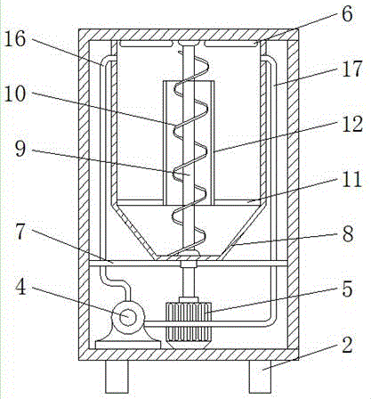
FIG. 1 is a schematic front view of the internal structure of the present invention;
FIG. 2 is a side view of the internal structure of the present invention;
FIG. 3 is a schematic front view of the present invention.
In the figure: 1. an outer box; 2. supporting legs; 3. a feed inlet; 4. a hot air blower; 5. a servo motor; 6. heating a tube; 7. a transverse plate; 8. a stirring barrel; 9. a stirring roller shaft; 10. helical leaves; 11. a support; 12. a sleeve; 13. a discharge pipe; 14. grooving; 15. a plugboard; 16. an air outlet pipe; 17. an air inlet pipe; 18. and (4) an observation window.
Detailed Description
The technical solutions in the embodiments of the present invention will be clearly and completely described below with reference to the drawings in the embodiments of the present invention, and it is obvious that the described embodiments are only a part of the embodiments of the present invention, and not all of the embodiments. All other embodiments, which can be obtained by a person skilled in the art without any inventive step based on the embodiments of the present invention, are within the scope of the present invention.
Referring to fig. 1 to 3, the present invention provides a technical solution: a trough mixer feed additive production device for veterinary drug production comprises an outer box 1, wherein four corners of the bottom end of the outer box 1 are respectively fixedly connected with supporting legs 2, the surface of the outer box 1 is fixedly connected with a feed inlet 3, the feed inlet 3 penetrates through the inner part of the outer box 1 to be connected with a stirring barrel 8, the bottom end of the inner part of the outer box 1 is sequentially and fixedly connected with a hot air blower 4 and a servo motor 5 from left to right, a plurality of heating pipes 6 are fixedly arranged at the top end of the inner part of the outer box 1 at equal intervals, a transverse plate 7 is fixedly connected to the inner wall of the outer box 1, the top end of the transverse plate 7 is fixedly connected with the stirring barrel 8, a stirring roller shaft 9 penetrates through the inner part of the stirring barrel 8 through a bearing, the bottom end of the stirring roller shaft 9 penetrates through the inner part of the transverse plate 7 through the bearing to be fixedly connected with the output end of the servo motor 5, spiral blades 10 are fixedly connected to the surface of the stirring roller shaft 9, a plurality of brackets 11 are fixedly connected to the inner wall of the stirring barrel 8 at equal angles, and the one end fixedly connected with sleeve 12 of support 11, discharging pipe 13 has been seted up to bottom one side of agitator 8, and discharging pipe 13 runs through and has seted up fluting 14 in two walls of the inside discharging pipe 13 of diaphragm 7 and outer container 1, and the inside grafting of fluting 14 has plugboard 15, one side fixedly connected with outlet duct 16 of agitator 8, and outlet duct 16 runs through and is connected in diaphragm 7 on the top of air heater 4, the one end and the intake pipe 17 fixed connection of air heater 4, and the other end of intake pipe 17 runs through and is connected in one side that outlet duct 16 was kept away from to diaphragm 7 and agitator 8, the surperficial embedded observation window 18 of outer container 1.
In this embodiment, as shown in fig. 1, the central axes of the stirring roller shaft 9, the sleeve 12 and the servo motor 5 are the same, and the helical blade 10 mixes and rotates the feed in the stirring barrel 8 by the cooperation of the servo motor 5 and the stirring roller shaft 9.
In this embodiment, as shown in fig. 1, the air outlet pipe 16 is connected to the air inlet pipe 17 through the air heater 4, and the hot air in the stirring barrel 8 returns to the inside of the stirring barrel 8 through the air inlet pipe 17 by the cooperation of the air outlet pipe 16 and the air heater 4, so that the hot air is recycled, and the moisture in the feed is removed.
In this embodiment, as shown in fig. 1, the sleeve 12 is connected to the mixing barrel 8 through the bracket 11, and under the cooperation of the bracket 11 and the sleeve 12, when the spiral blade 10 rotates, the unmixed feed at the bottom can be processed.
In this embodiment, as shown in fig. 1, six heating pipes 6 are provided, and each heating pipe is symmetrical with respect to the central axis of the stirring roll shaft 9, so that the heating pipes 6 are used for removing the moisture in the feed while the feed in the stirring barrel 8 is mixed and rotated.
In this embodiment, as shown in fig. 1, the discharge pipe 13 is an inclined structure, and the inclined discharge pipe 13 makes the discharge smoother by the gravity of the feed itself
The use method and the advantages of the utility model are as follows: this kind of cell type mixes quick-witted feed additive production facility of animal remedy production usefulness is when the rolling, and the working process is as follows:
as shown in fig. 1, fig. 2 and fig. 3, at first pour the fodder into from feed inlet 3, the fodder gets into agitator 8 inside, under servo motor 5 and the cooperation of stirring roller 9, spiral leaf 10 is to the fodder in agitator 8 from bottom to top the circulation mix, heating pipe 6 gives off the heat when mixing, evaporate the moisture in the fodder, get rid of the moisture in the fodder, the heat that heating pipe 6 gave off is the steam in agitator 8 simultaneously, under the cooperation of outlet duct 16 and air heater 4, get into the inside of agitator 8 by intake pipe 17 recirculation, dry many times the fodder, the fodder that the stirring is mixed is through the plugboard 15 of pulling the inside grafting of discharging pipe 13, utilize the gravity of fodder self, make the fodder discharge from discharging pipe 13.
The foregoing shows and describes the general principles, essential features, and advantages of the utility model. It will be understood by those skilled in the art that the present invention is not limited to the embodiments described above, and the preferred embodiments of the present invention are described in the above embodiments and the description, and are not intended to limit the present invention. The scope of the utility model is defined by the appended claims and equivalents thereof.