Metal tube automatic feeding equipment
Technical Field
The utility model relates to an injection moulding field especially indicates a tubular metal resonator automatic feeding equipment.
Background
In the prior art, a metal pipe (such as a steel pipe) is subjected to plastic coating treatment by an injection molding machine, so that the advantages of metal and plastic are combined, and a pipe fitting product with excellent performance is obtained. However, at present, the metal pipe is generally placed into an injection molding machine manually to be subjected to plastic coating treatment, so that the production efficiency is low and the safety is poor.
SUMMERY OF THE UTILITY MODEL
An object of the utility model is to provide a tubular metal resonator automatic feeding equipment, it can effectively improve production efficiency and production security.
In order to achieve the above purpose, the solution of the present invention is:
an automatic metal pipe feeding device comprises a metal pipe feeding unit, a metal pipe positioning unit and a metal pipe feeding unit; the metal pipe feeding unit is used for conveying the metal pipe to the metal pipe positioning unit; the metal pipe positioning unit is used for adjusting the position of the metal pipe conveyed to the metal pipe positioning unit so that the metal pipe is placed according to a preset position; the metal tube feeding unit is used for conveying the positioned metal tube to an injection molding machine.
The metal pipe positioning unit comprises a positioning jig, and a stop plate and a pushing mechanism which are respectively arranged on two sides of the positioning jig; the positioning jig is provided with a plurality of placing through grooves for placing the metal pipes; the pushing mechanism comprises a push plate and a push plate driving device connected with the push plate, and the push plate driving device drives the push plate to move towards or back to the stop plate.
The pushing mechanism further comprises a positioning adjusting device, and the positioning adjusting device is connected with the push plate driving device and controls the push plate driving device to move towards or back to the stop plate.
The positioning adjusting device comprises an adjusting screw rod, an adjusting nut, a locking assembly and two adjusting seats; the adjusting screw rod is rotatably connected with the two adjusting seats, the locking assembly is matched with the adjusting screw rod and controls whether the adjusting screw rod can rotate or not, and the adjusting nut is in threaded connection with the adjusting screw rod and is fixedly connected with the push plate driving device.
The locking assembly comprises a locking clamp with a clamping opening and a locking screw rod in threaded connection with two sides of the clamping opening of the locking clamp; the locking clamp is fixedly connected with an adjusting seat, and an adjusting screw rod is sleeved at a clamping opening of the locking clamp.
The metal pipe feeding unit comprises a material storage device and a material moving device; the material storage device is used for placing a material tray, and the material tray is used for containing the metal tubes; move the material device including being used for getting the material hand that moves of putting the tubular metal resonator and with move the triaxial sharp module that the material hand is connected, triaxial sharp module drive moves the material hand and carries out the triaxial translation.
Move the material device and still include rotary device, move the material hand and be connected with triaxial sharp module through rotary device, the rotary device drive moves the material hand and rotates, and triaxial sharp module drive moves the material hand and rotary device and carries out the triaxial translation together.
The material storage device comprises a lifting platform which is used for placing the material tray and can lift up and down, and a supporting component which is used for supporting the material tray; the supporting component comprises a supporting table and first supporting mechanisms, the supporting table is provided with a material tray opening through which the material feeding tray passes, the lifting table is installed below the supporting table and is arranged corresponding to the material tray opening, the number of the first supporting mechanisms is at least two, at least two first supporting mechanisms are arranged in each first supporting mechanism and are respectively arranged on two opposite sides of the material tray opening, and the first supporting mechanisms comprise supporting plates for supporting the material trays and supporting driving devices for driving the supporting plates to move horizontally.
The supporting assembly further comprises a second supporting mechanism, and the second supporting mechanism comprises a rotating device and a telescopic ejection device; the rotating device is matched with the supporting table, the rotating device is connected with the ejecting device and drives the ejecting device to rotate, and the ejecting device is used for ejecting the middle of the bottom side of the material tray.
The material storage device also comprises a material tray positioning assembly, wherein the material tray positioning assembly comprises two first material tray positioning devices which are respectively arranged on two opposite sides of a material tray opening of the supporting table and two second material tray positioning devices which are respectively arranged on the other two opposite sides of the material tray opening of the supporting table; the first tray positioning device comprises a first positioning plate and a first positioning driving device which is connected with the first positioning plate and drives the first positioning plate to move horizontally; the second tray positioning device comprises a second positioning plate and a second positioning driving device which is connected with the second positioning plate and drives the second positioning plate to move horizontally.
The metal tube feeding unit also comprises a material tray moving device; the charging tray moving and taking device comprises a charging tray mechanical arm and a charging tray driving device, wherein the charging tray mechanical arm is used for sucking a charging tray, and the charging tray driving device is used for driving the charging tray mechanical arm to move.
The metal pipe feeding unit comprises a feeding manipulator and a feeding driving device for driving the feeding manipulator to move; the feeding manipulator is provided with a plurality of grippers arranged side by side and a plurality of push rods arranged side by side.
The feeding manipulator is provided with a fixed seat, a push rod driving device is matched on the fixed seat, the push rod driving device is connected with a push plate and drives the push plate to translate, and the push plate is provided with a plurality of connecting holes; each push rod is mobilizable respectively and passes the fixing base, and each push rod is interference fit respectively with each connecting hole of slurcam, and the one end of every push rod forms backstop portion, and backstop portion and the slurcam of push rod are in the relative both sides of fixing base respectively, and every push rod cover is equipped with reset spring, and the backstop portion that leans on fixing base and push rod respectively is supported at reset spring's on every push rod both ends.
After the scheme is adopted, the utility model discloses a tubular metal resonator feed unit, tubular metal resonator positioning unit and tubular metal resonator material loading unit can realize putting into the injection molding machine with the tubular metal resonator is automatic, have reduced the manual work to improve production efficiency and production security when carrying out the package to the tubular metal resonator and moulding the processing.
Drawings
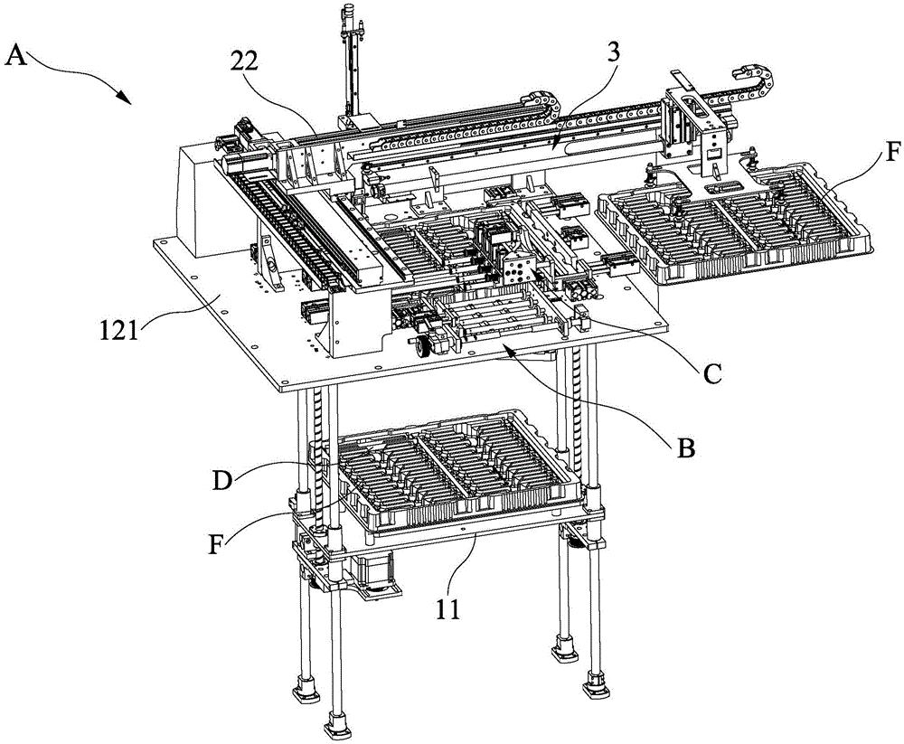
FIG. 1 is a schematic view of the present invention;
FIG. 2 is a schematic structural view of the present invention;
fig. 3 is a schematic structural view 1 of the storage device of the present invention;
fig. 4 is a schematic structural view 2 of the storage device of the present invention;
fig. 5 is a schematic view of the storing device according to the present invention;
fig. 6 is a schematic structural view of the material moving device of the present invention;
fig. 7 is a schematic structural view of the tray moving device of the present invention;
fig. 8 is a schematic structural diagram 1 of a metal pipe positioning unit according to the present invention;
fig. 9 is a schematic structural diagram 2 of the metal pipe positioning unit of the present invention;
fig. 10 is a schematic structural diagram 1 of a feeding manipulator according to the present invention;
fig. 11 is a schematic structural diagram of a loading manipulator of the present invention 2;
description of reference numerals:
a metal pipe supply unit a for supplying a metal pipe,
the material storing device 1, the lifting platform 11, the supporting component 12, the supporting platform 121, the material tray opening 1211, the first supporting mechanism 122, the supporting plate 1221, the supporting driving device 1222, the second supporting mechanism 123, the rotating device 1231, the pushing device 1232, the material tray positioning component 13, the first material tray positioning device 131, the first positioning plate 1311, the first positioning driving device 1312, the second material tray positioning device 132, the second positioning plate 1321, the second positioning driving device 1322, the material moving device 2, the material moving hand 21, the three-axis linear module 22, the rotating device 23, the material tray moving device 3, the material tray manipulator 31 and the material tray driving device 32,
a metal tube positioning unit B for positioning the metal tube,
a positioning jig 4, a placing through groove 41, a stop plate 5, a pushing mechanism 6, a push plate 61, a push plate driving device 62, a positioning adjusting device 63, an adjusting screw 631, an adjusting nut 632,
locking assembly 633, locking clamp 6331, locking screw 6332, adjustment mount 634,
a metal pipe feeding unit C for feeding a metal pipe,
a feeding manipulator 7, a gripper 71, a push rod 72, a stopping part 721, a fixed seat 73, a push rod driving device 74, a push plate 75, a return spring 76,
the metal tube (D) is a metal tube,
an injection molding machine E is used for injecting the mixture,
and a material tray F.
Detailed Description
In order to further explain the technical solution of the present invention, the present invention is explained in detail by the following embodiments.
As shown in fig. 1 to 11, the present invention discloses an automatic metal tube feeding device, which comprises a metal tube feeding unit a, a metal tube positioning unit B and a metal tube feeding unit C; wherein the metal tube supply unit A is for delivering the metal tube D to the metal tube positioning unit B; the metal tube positioning unit B is used for adjusting the position of the metal tube D conveyed to the metal tube positioning unit B, so that the metal tube D is placed according to a preset position; and the metal pipe feeding unit C is used for conveying the positioned metal pipe D to an injection molding machine E.
The utility model discloses a, the utility model discloses a tubular metal resonator feed unit A, tubular metal resonator positioning unit B and tubular metal resonator material loading unit C can realize putting into the injection molding machine with tubular metal resonator D is automatic, have reduced the manual work to production efficiency and production security when the processing are moulded to the package to the improvement tubular metal resonator.
In the utility model, the metal tube feeding unit A comprises a material storage device 1 and a material moving device 2; the storage device 1 is used for placing a material tray F, and the material tray F is used for containing the metal pipe D; the material moving device 2 is used for conveying the metal tube D contained on the material tray F to the metal tube positioning unit B.
In the present invention, the material moving device 2 may include a material moving hand 21 for taking and placing the metal tube D and a three-axis linear module 22 connected to the material moving hand 21, and the three-axis linear module 22 drives the material moving hand 21 to perform three-axis translation; when the material moving device 2 conveys the metal tube D, the material moving hand 21 firstly grabs the metal tube D contained on the material tray F, then the three-axis linear module 22 drives the material moving hand 21 to move to the metal tube positioning unit B, and the material moving hand 21 then places the metal tube D on the metal tube positioning unit B. The material moving device 2 can further comprise a rotating device 23, the material moving hand 21 is connected with a three-axis linear module 22 through the rotating device 23, the rotating device 22 drives the material moving hand 21 to rotate, and the three-axis linear module 22 drives the material moving hand 21 and the rotating device 23 to perform three-axis translation together; the utility model can drive the material moving hand 21 to rotate through the rotating device 23, and further can drive the metal tube D grabbed by the material moving hand 21, so as to adjust the placing direction of the metal tube D on the metal tube positioning unit B, and the metal tube D can be placed on the metal tube positioning unit B according to the preset direction; the rotating device 23 may employ a rotary air cylinder.
In the present invention, the material storage device 1 may include a lifting platform 11 for placing the material tray F and capable of lifting up and down, and a supporting component 12 for supporting the material tray F; the supporting assembly 12 includes a supporting table 121 and first supporting mechanisms 122, the supporting table 121 is provided with a material tray opening 1211 through which a material supply tray F passes, the lifting table 11 is installed below the supporting table 121 and is arranged corresponding to the material tray opening 1211, the number of the first supporting mechanisms 122 is at least two, at least two first supporting mechanisms 122 in each first supporting mechanism 122 are respectively arranged on two opposite sides of the material tray opening 1211, each first supporting mechanism 122 includes a supporting plate 1221 for supporting the material tray F and a supporting driving device 1222 for driving the supporting plate 1221 to translate, and the supporting driving device 1222 can adopt a telescopic cylinder; when the lifting platform 11 is lifted up to make the tray F placed on the lifting platform 11 pass through the tray opening 1211, the support driving device 1222 of each first support mechanism 122 drives the support plate 1221 to translate so that the support plate 1221 extends into the lower part of the tray F to support the tray F, and then the lifting platform 11 can be lowered. Through the arrangement, the utility model can stack a plurality of charging trays F on the lifting platform 11, the lifting platform 11 can sequentially send each charging tray F to the charging tray opening 1211 from top to bottom, and the material moving device 2 conveys the metal tube D contained on the charging tray F sent to the charging tray opening 1211 to the metal tube positioning unit B; when the lifting platform 11 delivers the last tray F to the tray opening 1211, the support driving device 1222 of each first support mechanism 122 drives the support plate 1221 to translate so that the support plate 1221 extends below the last tray F to support the last tray F, and then the lifting platform 11 can descend, so that an operator can stack a plurality of trays F on the lifting platform 11, which is helpful for improving the production efficiency. The support assembly 12 may further include a second support mechanism 123, the second support mechanism 123 includes a rotating device 1231 and a retractable pushing device 1232; the rotating device 1231 is matched with the support table 121, the rotating device 1231 is connected with the ejecting device 1232 and drives the ejecting device 1232 to rotate, and the ejecting device 1232 is used for ejecting the middle part of the bottom side of the tray F; after the tray F is supported by the first supporting mechanism 122, the rotating device 1231 can drive the pushing device 1232 to rotate, so that the pushing device 1232 rotates to a position below the middle part of the bottom side of the tray F, and then the pushing device 1232 extends to push the middle part of the bottom side of the tray F, thereby improving the supporting effect on the tray F; the rotating device 1231 may adopt a rotating cylinder or a rotating motor, and the pushing device 1232 may adopt a telescopic cylinder. The storing device 1 can further comprise a material tray positioning assembly 13, wherein the material tray positioning assembly 13 comprises two first material tray positioning devices 131 respectively arranged at two opposite sides of the material tray opening 1211 of the supporting table 121 and two second material tray positioning devices 132 respectively arranged at the other two opposite sides of the material tray opening 1211 of the supporting table 121; the first tray positioning device 131 comprises a first positioning plate 1311 and a first positioning driving device 1312 which is connected with the first positioning plate 1311 and drives the first positioning plate 1311 to translate; the second tray positioning device 132 comprises a second positioning plate 1321 and a second positioning driving device 1322 connected with the second positioning plate 1321 and driving the second positioning plate 1321 to translate. The utility model discloses when elevating platform 11 sent charging tray F to charging tray mouth 1211 department from bottom to top, the first positioning drive 1312 drive first locating plate 1311 translation of each first charging tray positioner 131 supports and leans on charging tray F, the second positioning drive 1322 drive second locating plate 1321 translation of each second charging tray positioner 132 supports and leans on charging tray F, thereby make the four sides of charging tray F who reachs charging tray mouth 1211 department support by first locating plate 1311 and second locating plate 1321 respectively and lean on, and then prescribe a limit to charging tray F's position, guarantee that charging tray F position is accurate.
In the utility model, the metal tube feeding unit A also comprises a material tray moving device 3; the tray moving and taking device 3 comprises a tray manipulator 31 for sucking the tray F and a tray driving device 32 for driving the tray manipulator 31 to move; after the metal tubes D on the material tray F are all taken away by the material moving device 2, the material tray manipulator 21 of the material tray moving device 3 sucks an empty material tray, and the empty material tray is conveyed to a specified position to be placed through the material tray driving device 32.
In the present invention, the metal pipe positioning unit B includes a positioning jig 4, and a stopper plate 5 and a pushing mechanism 6 respectively disposed at two sides of the positioning jig 4, and the positioning jig 4, the stopper plate 5 and the pushing mechanism 6 may be disposed at the supporting table 121; the positioning jig 4 is provided with a plurality of placing through grooves 41 for placing the metal tubes D, and the material moving device 2 conveys the metal tubes D to the placing through grooves 41 for placing; the pushing mechanism 6 comprises a pushing plate 61 and a pushing plate driving device 62 connected with the pushing plate 61, and the pushing plate driving device 62 drives the pushing plate 61 to move towards or back to the stop plate 5; after moving material device 2 and putting into tubular metal resonator D toward the logical groove 41 of placing of positioning jig 4, push pedal drive arrangement 62 drive push pedal 61 moves towards backstop 5 for tubular metal resonator D both ends support respectively and lean on backstop 5 and push pedal 61, thereby make tubular metal resonator D place according to preset position. The utility model discloses in, it still includes positioning adjustment device 63 to push mechanism 6, positioning adjustment device 63 is connected with push pedal drive arrangement 62 and controls push pedal drive arrangement 62 orientation or move dorsad backstop board 5, the utility model discloses a spacing between push pedal drive arrangement 62 and the backstop board 5 can be adjusted to positioning adjustment device 63 for tubular metal resonator positioning unit B is applicable in the tubular metal resonator D of multiple size. The positioning adjustment device 63 includes an adjustment screw 631, an adjustment nut 632, a locking assembly 633 and two adjustment seats 634; the adjusting screw 631 is rotatably connected with the two adjusting seats 634, the locking assembly 633 is matched with the adjusting screw 631 and controls whether the adjusting screw 631 can rotate, the adjusting nut 632 is in threaded connection with the adjusting screw 631, and the adjusting nut 632 is fixedly connected with the push plate driving device 62, the utility model discloses a rotation of the adjusting screw 631 can drive the push plate driving device 62 to move, thereby adjusting the distance between the push plate driving device 62 and the stop plate 5; when the distance between the push plate driver 62 and the stop plate 5 is adjusted, the locking assembly 633 locks the adjusting screw 631 so that the push plate driver 62 does not move. The locking assembly 633 comprises a locking clamp 6331 with a clamping opening and a locking screw 6332 in threaded connection with two sides of the clamping opening of the locking clamp 6331; the locking clamp 6331 is fixedly connected with an adjusting seat 634, and an adjusting screw rod 6332 is sleeved in a clamping opening of the locking clamp 6331; the utility model discloses a rotate locking screw 6332 and can make locking clamp 6331's the mouth that presss from both sides tight accommodate lead screw 6332, and then make accommodate lead screw 6332 unrotatable.
In the present invention, the metal pipe feeding unit C may include a feeding manipulator 7 and a feeding driving device (not shown) for driving the feeding manipulator 7 to move; the feeding manipulator 7 has a plurality of grippers 71 arranged side by side and a plurality of push rods 72 arranged side by side; the gripper 71 is used for taking and placing the metal pipe D placed in the metal pipe positioning unit B, and placing the metal pipe D in the injection molding machine E through the feeding driving device, so that the metal pipe D is inserted into a mold of the injection molding machine E; after the metal tube D is inserted into the mold, the push rod 72 may push against the metal tube D and the metal tube D is inserted into place. The feeding manipulator 7 is provided with a fixed seat 73, a push rod driving device 74 is matched on the fixed seat 73, the push rod driving device 74 is connected with a push plate 75, the push rod driving device 74 drives the push plate 75 to move horizontally, the push rod driving device 74 can be a telescopic cylinder, and the push plate 75 is provided with a plurality of connecting holes; each push rod 72 respectively movably penetrates through the fixed seat 73, each push rod 72 is in interference fit with each connecting hole of the push plate 75, a stopping part 721 is formed at one end of each push rod 72, the stopping part 721 of each push rod 72 and the push plate 75 are respectively positioned at two opposite sides of the fixed seat 73, each push rod 72 is sleeved with a return spring 76, and two ends of the return spring 76 on each push rod 72 respectively abut against the fixed seat 73 and the stopping part 721 of the push rod 72; the utility model has the advantages that the push rods 72 are in interference fit with the push plate 75, so that the push rod driving device 74 can drive each push rod 72 to translate in the positive direction through the push plate 75, and each push rod 72 pushes against the metal pipe D respectively; because the push rod 72 is in interference fit with the push plate 75, after the metal tube D is pushed to the proper position, the push rod driving device 74 continues to drive the push plate 75 to translate in the forward direction, so that the push rod 72 moves in the reverse direction relative to the push plate 75, and the metal tube D is prevented from being crushed by the push rod 72; after the metal tubes D are pushed to the right, the push rod driving device 74 drives the push plate 75 to translate and reset in the opposite direction, and at the same time, the reset spring 76 drives the push rod 72 to move in the forward direction relative to the push plate 75 to reset the push rod 72.
The above embodiments and drawings are not intended to limit the form and style of the present invention, and any suitable changes or modifications made by those skilled in the art should not be construed as departing from the scope of the present invention.