CN217536152U - Inductively coupled plasma reaction chamber - Google Patents
Inductively coupled plasma reaction chamber Download PDFInfo
- Publication number
- CN217536152U CN217536152U CN202221205391.7U CN202221205391U CN217536152U CN 217536152 U CN217536152 U CN 217536152U CN 202221205391 U CN202221205391 U CN 202221205391U CN 217536152 U CN217536152 U CN 217536152U
- Authority
- CN
- China
- Prior art keywords
- cavity
- reaction chamber
- plasma generator
- heightening
- inductively coupled
- Prior art date
- Legal status (The legal status is an assumption and is not a legal conclusion. Google has not performed a legal analysis and makes no representation as to the accuracy of the status listed.)
- Active
Links
Images


Landscapes
- Plasma Technology (AREA)
Abstract
The utility model relates to a reaction equipment technical field provides an inductive coupling plasma reaction chamber, including plasma generator, the last intercommunication of plasma generator has the air supply air inlet, and the last intercommunication of plasma generator has the cavity of round platform shape and increases the cavity in proper order, keeps away from its central point department of position equidistance on the cavity and encircles and be equipped with a plurality of mouths that spray, still is provided with the chamfer on the inner wall of spraying the mouth, and the intercommunication has the vacuum switching mouth on increasing the lateral wall of cavity, and increases and be connected with extraction opening and air inlet on the bottom of cavity. The utility model overcomes prior art's is not enough, reasonable in design, compact structure, cavity adopt round platform shape design, and reactant gas gets into the reaction chamber along conical direction diffusion, makes the even dispersion of reactant gas in the cavity, improves the homogeneity of deposited film.
Description
Technical Field
The utility model relates to a reaction unit technical field, concretely relates to inductive coupling plasma reaction chamber.
Background
In the process of implementing the technical scheme of the invention of the embodiment of the present application, the inventor of the present application finds that the above-mentioned technology has at least the following technical problems:
the atomic layer deposition is a special chemical vapor deposition method, precursor sources alternately enter a reaction cavity, chemical adsorption reaction is carried out on a deposition substrate, and a thin film grows in a layered mode. Atomic layer deposition includes Thermal Atomic Layer Deposition (TALD) and Plasma Enhanced Atomic Layer Deposition (PEALD). The reaction process of PEALD is mainly: (1) the precursor A enters a reaction cavity in a pulse mode, and chemical adsorption reaction is carried out on the surface of the substrate; (2) cleaning redundant precursor A and reaction byproducts by inert gas; (3) the reaction gas (plasma) B enters the reaction cavity and chemically reacts with the precursor source A on the substrate to generate a film; (4) the inert gas cleans the redundant reaction gas (plasma) B and reaction byproducts, a cycle process is completed, and the process is repeated to generate a thin film with the required film thickness.
The deposition film effect degree of consistency in the work of present plasma reaction chamber is not enough, and plasma can produce moreover with the closed angle department on the dish that sprays and discharge, thereby leads to producing the degree of consistency that further influences the deposition and imitate the film to the sample to influence easily, and equipment is also inconvenient moreover and other equipment docks, has influenced the convenience of equipment, for this reason, we provide an inductive coupling plasma reaction chamber.
SUMMERY OF THE UTILITY MODEL
Technical problem to be solved
Aiming at the defects of the prior art, the utility model provides an inductive coupling plasma reaction chamber, which overcomes the defects of the prior art, has reasonable design and compact structure, adopts the design of a round platform shape, and the reaction gas diffuses into the reaction chamber along the conical direction, so that the reaction gas is uniformly dispersed in the chamber, and the uniformity of the deposited film is improved;
the spray opening on the spray plate adopts a guide angle design, so that the contact between the plasma and the sharp corner is reduced, the influence of the sharp corner on the plasma is reduced, and the plasma discharge is reduced;
the center of the spray disk is not provided with a spray port, so that the influence of high-energy plasma in the center of the spray disk on a sample is reduced, and the uniformity of the film can be improved;
and increase the vacuum switching mouth on increasing the cavity, make things convenient for the other equipment of butt joint at the back, still saved manpower and material resources when increasing this equipment convenience.
(II) technical scheme
In order to achieve the above purpose, the utility model discloses a following technical scheme realizes:
the utility model provides an inductive coupling plasma reaction chamber, includes plasma generator, and the intercommunication has the air supply air inlet on the plasma generator, and the last intercommunication in proper order of plasma generator has the cavity of round platform shape and increases the cavity, keeps away from its central point department equidistance ring of position on the cavity and is equipped with a plurality of mouths that spray, still is provided with the chamfer on the inner wall of spraying the mouth, increases the intercommunication on the lateral wall of cavity and has the vacuum switching mouth, and increases and be connected with extraction opening and air inlet on the bottom of cavity.
Preferably, the cavity is sleeved with a spray disc connected to the heightening cavity.
Preferably, the bottom of the plasma generator is communicated with a truncated cone-shaped cavity through a flange, and the upper bottom surface of the cavity is slightly smaller than the lower bottom surface.
Preferably, the side wall of the heightening cavity is connected with a vacuum adapter, and the interface is KF, CF or ISO.
Preferably, the bottom of the heightening cavity is also connected with a bottom part, and the air suction port and the air inlet extend to the bottom part and are communicated with the heightening cavity.
Preferably, the plasma generator is made of a copper coil and a quartz tube.
(III) advantageous effects
The embodiment of the utility model provides an inductive coupling plasma reaction chamber. The method has the following beneficial effects:
1. through the round platform shape cavity that sets up, can make reaction gas along the diffusion of conical direction entering reaction chamber to make reaction gas even dispersion in the cavity, improve the homogeneity of deposited film.
2. The spray opening on the spray plate is designed into a lead angle, so that the contact between plasma and a sharp corner is reduced, the influence of the sharp corner on the plasma is reduced, and the plasma discharge is reduced; and the center of the spray plate is not provided with a spray opening, so that the influence of high-energy plasma in the center of the spray plate on a sample is reduced, and the uniformity of the film can be improved.
3. Through the arranged heightening cavity, the heightening cavity can increase the distance from the reaction gas to the cavity, so that ions and electrons in the reaction gas are recombined to generate gas molecules or atoms, and the bombardment on the substrate is reduced, thereby reducing the damage and the roughness to the substrate; and the vacuum adapter is added on the heightening cavity, so that the back of the heightening cavity is convenient to be connected with other equipment, and the manpower and material resources are saved.
Drawings
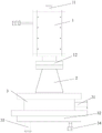
FIG. 1 is a schematic structural view of the present invention;
FIG. 2 is a schematic view of the structural cavity of the present invention;
fig. 3 is a schematic bottom view of the cavity of the present invention;
fig. 4 is a schematic view of the spray nozzle of the present invention.
In the figure: 1. a plasma generator; 11. an air source inlet; 12. a flange; 2. a cavity; 21. spraying a disc; 22. a spray port; 23. chamfering; 3. a heightening cavity; 31. a vacuum transfer port; 32. a bottom member; 33. an air extraction opening; 34. an air inlet.
Detailed Description
To make the purpose, technical solution and advantages of the embodiments of the present invention clearer, the attached drawings in the embodiments of the present invention are combined to clearly and completely describe the technical solution in the embodiments of the present invention, and obviously, the described embodiments are part of the embodiments of the present invention, rather than all embodiments. Based on the embodiments in the present invention, all other embodiments obtained by a person skilled in the art without creative work belong to the protection scope of the present invention.
Referring to the attached drawings 1-4, an inductively coupled plasma reaction chamber comprises a plasma generator 1, wherein a gas source gas inlet 11 is communicated with the plasma generator 1, the gas source gas inlet 11 is communicated with the top of the plasma generator 1 and is axially arranged to be conveniently connected with a gas source, the plasma generator 1 is sequentially communicated with a truncated cone-shaped cavity 2 and a heightened cavity 3, reaction gas can be diffused into the reaction chamber along the conical direction through the arranged truncated cone-shaped cavity 2 and is uniformly dispersed in the cavity 2, the uniformity of a deposited film is improved, a plurality of spray openings 22 are annularly arranged on the cavity 2 at equal intervals away from the center position of the cavity 2, the spray openings 22 can be uniformly distributed on the bottom of the cavity 2, the spray openings 22 are not formed in the center position of the cavity 2, chamfers 23 are further arranged on the inner walls of the spray openings 22, chamfers 23 which are inclined inwards are arranged on the pipeline edges at two ends of the spray openings 22, the spray openings 22 are designed into guide angles, the contact between plasma and sharp corners is reduced, the influence on plasma discharge is reduced, and plasma discharge is reduced; the central position of the spray disc 21 is not provided with the spray port 22, so that the influence of high-energy plasma in the center of the spray disc 21 on a sample is reduced, the uniformity of a film can be improved, the side wall of the heightening cavity 3 is communicated with the vacuum adapter port 31, the bottom of the heightening cavity 3 is connected with the air suction port 33 and the air inlet 34, the air inlet 34 is connected with the precursor source transmission system, the air suction port 33 is connected with the vacuum system, the distance from reaction gas to the cavity can be increased through the heightening cavity 3, ions and electrons in the reaction gas are recombined to generate gas molecules or atoms, and the bombardment on a substrate is reduced, so that the damage and the roughness on the substrate are reduced; and increase the vacuum switching mouth on increasing the cavity, make things convenient for the back to other equipment, saved manpower and material resources.
In this embodiment, the chamber 2 is sleeved with a shower tray 21 connected to the height-increasing chamber 3.
In this embodiment, the bottom of the plasma generator 1 is communicated with the circular truncated cone-shaped cavity 2 through the flange 12, the upper bottom surface of the cavity 2 is slightly smaller than the lower bottom surface, and the flange 12 is connected with the CF flange to increase the sealing effect.
In this embodiment, the sidewall of the heightening cavity 3 is connected with at least one vacuum adapter 31, and the interface is KF, CF or ISO, etc., so as to increase convenience.
In this embodiment, the bottom of the height increasing cavity 3 is further connected with a bottom part 32, and the suction opening 33 and the air inlet 34 extend to the bottom part 32 and are communicated in the height increasing cavity 3.
In this embodiment, the plasma generator 1 is made of a copper coil and a quartz tube, and the plasma generator 1 is sealed by a screw.
It is noted that, herein, relational terms such as first and second, and the like may be used solely to distinguish one entity or action from another entity or action without necessarily requiring or implying any actual such relationship or order between such entities or actions. Also, the terms "comprises," "comprising," or any other variation thereof, are intended to cover a non-exclusive inclusion, such that a process, method, article, or apparatus that comprises a list of elements does not include only those elements but may include other elements not expressly listed or inherent to such process, method, article, or apparatus. Without further limitation, an element defined by the phrase "comprising a … …" does not exclude the presence of another identical element in a process, method, article, or apparatus that comprises the element.
The above embodiments are only used to illustrate the technical solution of the present invention, and not to limit it; although the present invention has been described in detail with reference to the foregoing embodiments, it should be understood by those skilled in the art that: the technical solutions described in the foregoing embodiments may still be modified, or some technical features may be equivalently replaced; such modifications and substitutions do not depart from the spirit and scope of the present invention in its corresponding aspects.
Claims (6)
1. An inductively coupled plasma reaction chamber comprises a plasma generator (1), wherein a gas source gas inlet (11) is communicated with the plasma generator (1);
the method is characterized in that: the plasma generator (1) is sequentially communicated with a truncated cone-shaped cavity (2) and a heightened cavity (3);
a plurality of spraying ports (22) are annularly arranged on the cavity (2) at equal intervals away from the center of the cavity, and chamfers (23) are further arranged on the inner walls of the spraying ports (22);
the side wall of the heightening cavity (3) is communicated with a vacuum adapter (31), and the bottom of the heightening cavity (3) is connected with an air suction port (33) and an air inlet (34).
2. The inductively coupled plasma reactor chamber of claim 1 wherein: the cavity (2) is sleeved with a spray disc (21) connected to the heightening cavity (3).
3. An inductively coupled plasma reaction chamber as recited in claim 1, wherein: the bottom of the plasma generator (1) is communicated with the truncated cone-shaped cavity (2) through a flange (12), and the upper bottom surface of the cavity (2) is slightly smaller than the lower bottom surface.
4. The inductively coupled plasma reactor chamber of claim 1 wherein: the side wall of the heightening cavity (3) is connected with at least one vacuum adapter (31) which is KF, CF or ISO.
5. An inductively coupled plasma reaction chamber as recited in claim 1, wherein: the bottom of the heightening cavity (3) is also connected with a bottom part (32), and the air suction opening (33) and the air inlet (34) extend to the bottom part (32) and are communicated in the heightening cavity (3).
6. An inductively coupled plasma reaction chamber as recited in claim 1, wherein: the plasma generator (1) is made of a copper coil and a quartz tube.
Priority Applications (1)
| Application Number | Priority Date | Filing Date | Title |
|---|---|---|---|
| CN202221205391.7U CN217536152U (en) | 2022-05-18 | 2022-05-18 | Inductively coupled plasma reaction chamber |
Applications Claiming Priority (1)
| Application Number | Priority Date | Filing Date | Title |
|---|---|---|---|
| CN202221205391.7U CN217536152U (en) | 2022-05-18 | 2022-05-18 | Inductively coupled plasma reaction chamber |
Publications (1)
| Publication Number | Publication Date |
|---|---|
| CN217536152U true CN217536152U (en) | 2022-10-04 |
Family
ID=83435940
Family Applications (1)
| Application Number | Title | Priority Date | Filing Date |
|---|---|---|---|
| CN202221205391.7U Active CN217536152U (en) | 2022-05-18 | 2022-05-18 | Inductively coupled plasma reaction chamber |
Country Status (1)
| Country | Link |
|---|---|
| CN (1) | CN217536152U (en) |
-
2022
- 2022-05-18 CN CN202221205391.7U patent/CN217536152U/en active Active
Similar Documents
| Publication | Publication Date | Title |
|---|---|---|
| CN106609363B (en) | Semiconductor manufacturing system including deposition apparatus | |
| US6189485B1 (en) | Plasma CVD apparatus suitable for manufacturing solar cell and the like | |
| JP6240607B2 (en) | Gas delivery and distribution for homogeneous processes in a linear large area plasma reactor. | |
| TWI871332B (en) | Isolator apparatus and methods for substrate processing chambers | |
| US20230057432A1 (en) | Ceramic coated quartz lid for processing chamber | |
| CN217536152U (en) | Inductively coupled plasma reaction chamber | |
| CN104762609A (en) | Process and device of forming multilayer insulating thin film on inner wall of glass container | |
| CN110010431B (en) | Preparation method of microchannel plate with ion feedback prevention film | |
| CN116516317A (en) | Carrier boat, treatment equipment and method for controlling pressure drop in carrier boat | |
| CN103915307A (en) | Plasma process chamber and gas injection apparatus for same | |
| TWI615504B (en) | Plasma generating device for remote plasma enhanced chemical vapor deposition system | |
| TWM611114U (en) | Injector of vertical furnace for low pressure chemical vapor deposition (lpcvd) system | |
| CN208857359U (en) | Equipment for producing thin film and its reaction cavity | |
| KR20220030541A (en) | Apparatus for processing substrate | |
| CN110565072B (en) | A method of atomic layer deposition | |
| TW202514717A (en) | A focusing ring and a semiconductor process chamber | |
| CN105695958B (en) | A kind of PECVD gas spray, film forming chamber and working method | |
| KR20250011683A (en) | Atomic Layer Deposition Device | |
| CN103774120A (en) | Gas uniformizing device for PECVD (Plasma Enhanced Chemical Vapor Deposition) system | |
| CN210711738U (en) | PECVD film deposition chamber | |
| JPH06236850A (en) | Plasma processing apparatus | |
| TW202333230A (en) | Plasma processing method and plasma processing apparatus | |
| CN102758192B (en) | Semiconductor epitaxial wafer substrate-bearing disk, supporting device thereof and metal organic chemical vapor deposition (MOCAD) reaction chamber | |
| TW201213602A (en) | Apparatus for large area atmospheric pressure plasma enhanced chemical vapor deposition without electrode and film contaminations | |
| JPH02184022A (en) | Cvd electrode |
Legal Events
| Date | Code | Title | Description |
|---|---|---|---|
| GR01 | Patent grant | ||
| GR01 | Patent grant |