CN217536404U - Electric clothes airing machine control circuit with human body induction function - Google Patents
Electric clothes airing machine control circuit with human body induction function Download PDFInfo
- Publication number
- CN217536404U CN217536404U CN202220787590.7U CN202220787590U CN217536404U CN 217536404 U CN217536404 U CN 217536404U CN 202220787590 U CN202220787590 U CN 202220787590U CN 217536404 U CN217536404 U CN 217536404U
- Authority
- CN
- China
- Prior art keywords
- module
- relay
- electrically connected
- external interface
- controlling
- Prior art date
- Legal status (The legal status is an assumption and is not a legal conclusion. Google has not performed a legal analysis and makes no representation as to the accuracy of the status listed.)
- Active
Links
- 230000006698 induction Effects 0.000 title claims description 18
- 238000001514 detection method Methods 0.000 claims abstract description 14
- 230000005611 electricity Effects 0.000 claims description 32
- 238000001035 drying Methods 0.000 claims description 20
- 238000004659 sterilization and disinfection Methods 0.000 claims description 16
- 238000007605 air drying Methods 0.000 claims description 4
- 239000003990 capacitor Substances 0.000 claims description 3
- 230000000630 rising effect Effects 0.000 claims description 3
- 238000012806 monitoring device Methods 0.000 claims description 2
- 230000000249 desinfective effect Effects 0.000 abstract 1
- 230000001954 sterilising effect Effects 0.000 description 10
- 238000005286 illumination Methods 0.000 description 5
- 238000010586 diagram Methods 0.000 description 3
- 229910000831 Steel Inorganic materials 0.000 description 2
- 230000006378 damage Effects 0.000 description 2
- 239000010959 steel Substances 0.000 description 2
- 230000001960 triggered effect Effects 0.000 description 2
- 208000027418 Wounds and injury Diseases 0.000 description 1
- 230000000694 effects Effects 0.000 description 1
- 208000014674 injury Diseases 0.000 description 1
- 238000000034 method Methods 0.000 description 1
Images


Landscapes
- Circuit Arrangement For Electric Light Sources In General (AREA)
Abstract
The utility model provides an electronic airing machine control circuit of human response in area, including the main control chip module, the power supply module, wireless transceiver module, a human infrared sensor module for sending human sensing signal to the main control chip module when sensing the human body, a light detection module for detecting current environment light intensity, a first relay module for controlling disinfecting equipment power break-make, a second relay module for controlling lighting apparatus power break-make, a third relay module for controlling elevator motor power break-make, a relay drive module for driving first relay module, second relay module and the work of third relay module. The utility model provides a pair of take electronic airing machine control circuit of human response can be according to whether the existence of people control airing machine light, whether the start-up of functional unit such as sterilamp, make airing machine more intelligent, humanized.
Description
Technical Field
The utility model relates to an electronic circuit technical field especially relates to an electronic airing machine control circuit of human response in area.
Background
At present, with social development and technological innovation, people's daily life is more and more intelligent, and simultaneously, more and more intelligent furniture appear in people's daily life, and electric airer is because of possessing multiple functions, like being equipped with functional component such as light, sterilamp, its effect of facilitating the use also is the intelligent furniture that receives people's love and select for use often.
However, in practice, the existing electric clothes drying machine does not have human body induction, so that whether functional components such as an illuminating lamp and a sterilizing lamp are started or not can not be controlled according to the existence of people, the intelligent degree is low, and the humanization is insufficient; when the sterilizing lamp of the clothes drying machine is turned on, people enter the balcony, and ultraviolet rays can possibly irradiate the people to cause damage to the human body.
Therefore, it is desirable to provide a control circuit of an electric clothes drying machine with human body induction to solve the above technical problems.
SUMMERY OF THE UTILITY MODEL
The utility model discloses the technical problem of main solution provides an electronic airing machine control circuit of human response in area, can be according to whether the existence of people control airing machine light, whether the start of functional unit such as sterilamp, make airing machine more intelligent, humanized.
In order to solve the technical problem, the utility model adopts a technical scheme that an electric clothes airing machine control circuit with human body induction is provided, which comprises a main control chip module 1, a human body infrared sensor module 2 used for sending human body induction signals to the main control chip module 1 when a human body is induced, a power supply module 3 used for providing required power for each module, a light detection module 4 used for detecting the intensity of light in the current environment, a relay drive module 9 used for receiving control data signals sent by a control terminal, sending the control data signals to the main control chip module 1, receiving module data signals sent by the main control chip module 1 and sending the module data signals to a wireless transceiver module 5 of the control terminal, a first relay module 6 used for controlling the on-off of a power supply of a disinfection device, a second relay module 7 used for controlling the on-off of a power supply of a lighting device, a third relay module 8 used for controlling the on-off of a power supply of a lifting motor, and a relay drive module 9 used for driving the first relay module 6, the second relay module 7 and the third relay module 8 to work;
the infrared monitoring device comprises a main control chip module 1, a human body infrared sensor module 2, a light ray detection module 4, a relay driving module 9 and an external interface CN9, wherein the external interface CN9 is used for being electrically connected with a limit switch on the lifting motor, the signal output end of the human body infrared sensor module 2 and the signal output end of the light ray detection module 4 are respectively and electrically connected with the main control chip module 1, and the signal input end of the relay driving module 9 is electrically connected with the main control chip module 1.
In the examples, it is preferred that:
and the signal output end of the relay driving module 9 is also electrically connected with a fourth relay module 10 for controlling the on-off of the power supply of the drying equipment and a fifth relay module 11 for controlling the on-off of the power supply of the air drying equipment.
In the examples, it is preferred that:
the fourth relay module 10 comprises an external interface CN1 and an external interface CN2 for externally connecting the drying device, a relay switch K4 for controlling the on-off of the power supply of the drying device, and a relay coil L4 for controlling the on-off of the relay switch K4 when power is supplied, wherein one end of the external interface CN1 is electrically connected with a zero line N, the other end of the external interface CN1 is electrically connected with a live line L through the relay switch K4, one end of the external interface CN2 is electrically connected with the zero line N, the other end of the external interface CN2 is electrically connected with the live line L through the relay switch K4, and the relay coil L4 is electrically connected with the signal output end of the relay driving module 9;
including being used for external in the fifth relay module 11 air-dry the equipment to external interface CN3 and external interface CN4, be used for control air-dry the relay switch K5 of equipment power break-make, be used for controlling when getting the electricity relay switch K5 closed relay coil L5, the one end and the zero line N electricity of external interface CN3 are connected, the other end passes through relay switch K5 is connected with live wire L electricity, the one end and the zero line N electricity of external interface CN4 are connected, the other end passes through relay switch K5 is connected with live wire L electricity, relay coil L5 with the signal output part electricity of relay drive module 9 is connected.
In the examples, it is preferred that:
the first relay module 6 comprises an external interface CN5 and an external interface CN6 for externally connecting the disinfection equipment, a relay switch K1 for controlling the on-off of the power supply of the disinfection equipment and a relay coil L1 for controlling the on-off of the relay switch K1 when power is on, one end of the external interface CN5 is electrically connected with a zero line N, the other end of the external interface CN5 is electrically connected with a live line L through the relay switch K1, one end of the external interface CN6 is electrically connected with the zero line N, the other end of the external interface is electrically connected with the live line L through the relay switch K1, and the relay coil L1 is electrically connected with the signal output end of the relay driving module 9;
the second relay module 7 comprises an external interface CN7 for externally connecting the lighting equipment, a relay switch K2 for controlling the on-off of a power supply of the lighting equipment and a relay coil L2 for controlling the on-off of the relay switch K2 when power is obtained, one end of the external interface CN7 is electrically connected with a zero line N, the other end of the external interface CN is electrically connected with a live line L through the relay switch K1, and the relay coil L2 is electrically connected with a signal output end of the relay driving module 9;
the third relay module 8 includes an external interface CN8 for externally connecting the lifting motor, a relay switch K31 for controlling on/off of a rising power supply of the lifting motor, a relay switch K32 for controlling on/off of a falling power supply of the lifting motor, a relay coil L31 for controlling on/off of the relay switch K31 when power is supplied, and a relay coil L32 for controlling on/off of the relay switch K32 when power is supplied, the relay switch K31 and the relay switch K32 respectively include a movable contact, a normally open contact and a normally open contact therein, one end of the external interface CN8 is electrically connected with the movable contact of the relay switch K31, and the other end thereof is electrically connected with the movable contact of the relay switch K32, the normally open contact of the relay switch K31 and the normally open contact of the relay switch K32 are respectively electrically connected with a starting power supply for controlling starting of the lifting motor, the normally closed contact of the relay switch K31 and the contact of the relay switch K32 are respectively grounded, and the normally closed coil L31 and the relay coil L32 are respectively electrically connected with a signal output end of the relay drive module 9.
In the examples, it is preferred that:
the relay driving module 9 comprises a darlington chip IC1 for driving the first relay module 6, the second relay module 7 and the third relay module 8 to work, and a buzzer BZ1 for sounding when the darlington chip IC1 is just started to work or is down, wherein a signal input end of the darlington chip IC1 is electrically connected with the main control chip module 1, and a signal output end of the darlington chip IC1 is electrically connected with the buzzer BZ1, the first relay module 6, the second relay module 7 and the third relay module 8 respectively.
In the examples, it is preferred that:
human infrared sensor chip U1 that is used for exporting high level signal when sensing the human body in the human infrared sensor module 2 with be used for receiving the NMOS pipe Q3 that ends when human infrared sensor chip U1 exports high level signal, NMOS pipe Q3's source electrode with human infrared sensor chip U1's signal output part electricity is connected, NMOS pipe Q3's drain electrode with main control chip module 1's signal input part electricity is connected, NMOS pipe Q3's grid with power supply module 3's power output part electricity is connected, be connected with resistance R45 between NMOS pipe Q3's source electrode and the grid.
In the examples, it is preferred that:
the light detection module 4 comprises a photosensitive diode LED2 used for detecting the intensity of light in the current environment, the anode power end of the photosensitive diode LED2 is connected, and the cathode of the photosensitive diode LED2 is electrically connected with the signal input end of the main control chip module 1 through a parallel circuit consisting of a capacitor C63 and a resistor R19.
The utility model has the advantages that: the utility model provides a pair of take electronic airing machine control circuit of human response can be according to whether the existence of people control airing machine light, whether the start-up of functional unit such as sterilamp, make airing machine more intelligent, humanized.
Drawings
Fig. 1 is a schematic block diagram of a circuit structure of a control circuit of an electric clothes airing machine with human body induction of the utility model;
fig. 2 is a schematic circuit diagram of the main control chip module, the human body infrared sensor module and the light detection module shown in fig. 1;
FIG. 3 is a circuit schematic of the power supply module shown in FIG. 1;
fig. 4 is a circuit schematic of the wireless transceiver module shown in fig. 1;
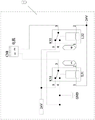
FIG. 5 is a circuit schematic of the first, second, fourth, and fifth relay modules shown in FIG. 1;
FIG. 6 is a circuit schematic of the third relay module shown in FIG. 1;
fig. 7 is a schematic circuit diagram of the relay drive module shown in fig. 1.
Detailed Description
The technical solution of the present invention will be described in detail with reference to the drawings.
Referring to fig. 1, the electric clothes airing machine control circuit with human body induction according to the present embodiment includes a main control chip module 1, a human body infrared sensor module 2 for sending a human body induction signal to the main control chip module 1 when a human body is induced, a power supply module 3 for providing required power to each module, a light detection module 4 for detecting the intensity of current ambient light, a wireless transceiver module 5 for receiving a control data signal sent by a control terminal and sending the control data signal to the main control chip module 1 and receiving each module data signal sent by the main control chip module 1 and sending the data signal to the control terminal, a first relay module 6 for controlling the power on/off of a disinfection device, a second relay module 7 for controlling the power on/off of a lighting device, a third relay module 8 for controlling the power on/off of a lifting motor, and a driving relay module 9 for driving the first relay module 6, the second relay module 7 and the third relay module 8 to work;
the infrared human body sensor module comprises a main control chip module 1, a human body infrared sensor module 2, a light detection module 4, a relay drive module 9 and an external interface CN9, wherein the external interface CN9 is used for being electrically connected with a limit switch on a lifting motor and is arranged in the main control chip module 1, the signal output end of the human body infrared sensor module 2 and the signal output end of the light detection module 4 are respectively and electrically connected with the main control chip module 1, and the signal input end of the relay drive module 9 is electrically connected with the main control chip module 1.
In this embodiment, when the main control chip module 1 obtains the human body sensing signal sent by the human body infrared sensor module 2, if the current main control chip module 1 learns that the current ambient light intensity is weak from the light detection module 4, then the main control chip module 1 can send an illumination signal to the relay driving module 9, so that the relay driving module 9 drives the second relay module 7 to control the lighting device to be turned on, thereby implementing the automatic illumination function, and then the human body infrared sensor module 2 can send an unmanned body sensing signal to the main control chip module 1 when the human body infrared sensor module 2 cannot sense the human body within a specified time, for example, 10S, and then the main control chip module 1 can send a signal for stopping illumination to the relay driving module 9, so that the relay driving module 9 controls the second relay module 7 to be powered off, thereby turning off the power supply of the lighting device, thereby implementing the automatic illumination function to turn off, so as to achieve the function of controlling the starting or not starting of the lighting device functional components of the clothes drying machine according to the existence of people described in this application, thereby making the clothes drying machine more intelligent and humanized, and facilitating the use of the machine at night.
In this embodiment, when the main control chip module 1 acquires a human body sensing signal sent by the human body infrared sensor module 2, the main control chip module 1 may send a sterilization stopping signal to the relay driving module 9, so that the relay driving module 9 controls the first relay module 6 to lose power and then to disconnect the conduction power supply of the sterilization apparatus, so as to control the sterilization apparatus to be turned off, then, when the human body infrared sensor module 2 cannot sense a human body within a specified time, for example, within 10S, the human body infrared sensor module 2 may send a no human body sensing signal to the main control chip module 1, and then, the main control chip module 1 may send a sterilization signal to the relay driving module 9, so that the relay driving module drives the first relay module 6 to control the sterilization apparatus to be turned on, thereby implementing an automatic illumination function, so as to achieve whether the clothes airing machine sterilization lamp function component can be controlled to be turned on or not according to the existence of a human body, so that the clothes airing machine is more intelligent and humanized while protecting the human body from ultraviolet light injury.
In this embodiment, when the main control chip module 1 acquires the lifting control signal for the lifting motor received by the wireless transceiver module 5, the main control chip module 1 may send a relevant lifting signal to the relay driving module 9 according to the lifting control signal, so that the relay driving module 9 drives the third relay module 8 to control the lifting of the lifting motor, thereby implementing the function of automatic lifting.
In this embodiment, the external interface CN9 electrically connected to the limit switch on the elevator motor corresponds to the resistance encountering function, the upper limit function and the lower limit function on the external interface CN9, that is, when the elevator motor encounters a resistance in the descending process, the steel wire rope becomes loose, and the limit switch is triggered to obtain a resistance encountering signal, so that when the main control chip module 1 obtains the resistance encountering signal sent by the external interface CN9, the main control chip module 1 can send a stop signal to the relay driving module 9 according to the resistance encountering signal, so that the relay driving module 9 controls the third relay module 8 to lose power and then disconnects the conduction power supply of the elevator motor, thereby implementing the resistance encountering function of the elevator motor; when the lifting motor ascends to the right position, the steel wire rope can be tensioned, the limit switch can be triggered to obtain an upper limit signal, and then when the main control chip module 1 obtains the upper limit signal sent by the external interface CN9, the main control chip module 1 can send a stop signal to the relay driving module 9 according to the upper limit signal, so that the relay driving module 9 controls the third relay module 8 to lose power and then cuts off the conduction power supply of the lifting motor, and the upper limit function of the lifting motor is realized.
In this embodiment, the limit switch of the present application may include a mechanical switch disposed on the lift motor, or may be a sensor module disposed on the lift motor, and the present application is not limited in any way.
Referring to fig. 2, in the embodiment of the present invention, it is preferable that:
including being used for exporting high level signal's human infrared sensor chip U1 when sensing the human body in human infrared sensor module 2 and being used for receiving the NMOS pipe Q3 that ends when human infrared sensor chip U1 exports high level signal, NMOS pipe Q3's source electrode is connected with human infrared sensor chip U1's signal output part electricity, NMOS pipe Q3's drain electrode is connected with main control chip module 1's signal input part electricity, NMOS pipe Q3's grid is connected with power supply module 3's power output part electricity, be connected with resistance R45 between NMOS pipe Q3's source electrode and the grid.
In this embodiment, when human infrared sensor chip U1 senses a human body, can be to NMOS pipe Q3's source output high level signal, and then NMOS pipe Q3 high level is ended, and then the level on main control chip module 1 can be in the high level state with the drain electrode electricity of NMOS pipe Q3, in order to pull up its level, then main control chip module 1 can confirm that human infrared sensor module 2 senses a human body, and when human infrared sensor chip U1 does not sense a human body, can be to NMOS pipe Q3's source output low level signal, and then NMOS pipe Q3 low level switches on, then can pull down the level on main control chip module 1 with NMOS pipe Q3's drain electrode electricity connection, and then main control chip module 1 can confirm that human infrared sensor module 2 does not sense a human body.
Referring to fig. 2, in the embodiment of the present invention, it is preferable that:
the light detection module 4 comprises a photosensitive diode LED2 used for detecting the intensity of light in the current environment, the anode power end of the photosensitive diode LED2 is connected, and the cathode of the photosensitive diode LED2 is electrically connected with the signal input end of the main control chip module 1 through a parallel circuit consisting of a capacitor C63 and a resistor R19.
Referring to fig. 5, in the embodiment of the present invention, it is preferable that:
and the signal output end of the relay driving module 9 is also electrically connected with a fourth relay module 10 for controlling the on-off of the power supply of the drying equipment and a fifth relay module 11 for controlling the on-off of the power supply of the air drying equipment.
In this embodiment, the signal output terminal of the relay driving module 9 of this application can be electrically connected with other functional devices besides the relay module which is used for controlling the drying device, the air drying device, the sterilizing device, the lighting device and the lifting motor device and mentioned in this application, and this application is not limited in any way.
Referring to fig. 5, in the embodiment of the present invention, it is preferable that:
the fourth relay module 10 comprises an external interface CN1 and an external interface CN2 for externally connecting the drying device, a relay switch K4 for controlling the on-off of the power supply of the drying device, and a relay coil L4 for controlling the on-off of the relay switch K4 when power is on, wherein one end of the external interface CN1 is electrically connected with a zero line N, the other end of the external interface CN1 is electrically connected with a live line L through the relay switch K4, one end of the external interface CN2 is electrically connected with the zero line N, the other end of the external interface is electrically connected with the live line L through the relay switch K4, and the relay coil L4 is electrically connected with the signal output end of the relay driving module 9;
including external interface CN3 and the external interface CN4 that is used for external air-dry equipment in the fifth relay module 11, a relay switch K5 for controlling air-dry equipment power break-make, a relay coil L5 for controlling relay switch K5 closed when getting power, the one end and the zero line N electricity of external interface CN3 are connected, the other end passes through relay switch K5 and is connected with live wire L electricity, the one end and the zero line N electricity of external interface CN4 are connected, the other end passes through relay switch K5 and is connected with live wire L electricity, relay coil L5 is connected with relay drive module 9's signal output part electricity.
Referring to fig. 5, in the embodiment of the present invention, it is preferable that:
the first relay module 6 comprises an external interface CN5 and an external interface CN6 for externally connecting disinfection equipment, a relay switch K1 for controlling the on-off of a power supply of the disinfection equipment and a relay coil L1 for controlling the on-off of the relay switch K1 during power-on, one end of the external interface CN5 is electrically connected with a zero line N, the other end of the external interface CN is electrically connected with a live line L through the relay switch K1, one end of the external interface CN6 is electrically connected with the zero line N, the other end of the external interface is electrically connected with the live line L through the relay switch K1, and the relay coil L1 is electrically connected with a signal output end of the relay driving module 9;
including being used for external lighting apparatus's external interface CN7 in the second relay module 7, a relay switch K2 for controlling lighting apparatus power break-make, a relay coil L2 for controlling relay switch K2 closed when getting the electricity, the one end and the zero line N electricity of external interface CN7 are connected, the other end passes through relay switch K1 and is connected with live wire L electricity, relay coil L2 is connected with the signal output part electricity of relay drive module 9.
Referring to fig. 6, in the embodiment of the present invention, it is preferable that:
the third relay module 8 includes an external interface CN8 for externally connecting the elevator motor, a relay switch K31 for controlling the on/off of the rising power supply of the elevator motor, a relay switch K32 for controlling the on/off of the falling power supply of the elevator motor, a relay coil L31 for controlling the closing of the relay switch K31 when power is obtained, and a relay coil L32 for controlling the closing of the relay switch K32 when power is obtained, wherein the relay switch K31 and the relay switch K32 respectively include a movable contact, a normally open contact and a normally open contact, one end of the external interface CN8 is electrically connected with the movable contact of the relay switch K31, the other end is electrically connected with the movable contact of the relay switch K32, the normally open contact of the relay switch K31 and the normally open contact of the relay switch K32 are respectively electrically connected with the starting power supply for controlling the start of the elevator motor, the normally closed contact of the relay switch K31 and the normally closed contact of the relay switch K32 are respectively grounded, and the relay coil L31 and the relay coil L32 are respectively electrically connected with the signal output end of the relay drive module 9.
In this embodiment, when the lifting motor needs to be controlled to perform the lifting operation, the main control chip module 1 may send a relevant control signal to the relay driving module 9, and then the relay coil L31 may be controlled by the relay driving module 9 to be powered on, so that the relay switch K31 is powered on, and then the power may be positively input to the lifting motor through the external interface CN8, and then the lifting motor may be powered on to perform the lifting operation.
In this embodiment, when the lifting motor needs to be controlled to descend, the main control chip module 1 may send a relevant control signal to the relay driving module 9, and then the relay driving module 9 may control the relay coil L32 to be powered on, so as to enable the relay switch K32 to be closed, and then the power may be reversely input to the lifting motor through the external interface CN8, and then the lifting motor may descend when being powered on.
Referring to fig. 7, in the embodiment of the present invention, it is preferable that:
the relay driving module 9 comprises a darlington chip IC1 for driving the first relay module 6, the second relay module 7 and the third relay module 8 to work, and a buzzer BZ1 for sounding when the darlington chip IC1 is just started to work or is down, wherein a signal input end of the darlington chip IC1 is electrically connected with the main control chip module 1, and a signal output end of the darlington chip IC1 is respectively and electrically connected with the buzzer BZ1, the first relay module 6, the second relay module 7 and the third relay module 8.
It can be seen that, the implementation of the electric clothes drying machine control circuit with human body induction described in fig. 1 to 7 can control whether functional components such as a clothes drying machine illuminating lamp and a sterilizing lamp are started or not according to the existence of people, so that the clothes drying machine is more intelligent and humanized.
In addition, the electric clothes airing machine control circuit with the human body induction, which is described in fig. 1 to 7, can increase the product intelligence degree and simultaneously protect the human body from being damaged by ultraviolet light.
The above is only the embodiment of the present invention, not limiting the scope of the present invention, all the equivalent structures made by the contents of the specification and the drawings, or directly or indirectly applied to other related technical fields, are included in the same reason as the protection scope of the present invention.
Claims (7)
1. The utility model provides a take electric airer control circuit of human response which characterized in that: the intelligent human body disinfection system comprises a main control chip module (1), a human body infrared sensor module (2) used for sending human body induction signals to the main control chip module (1) when a human body is sensed, a power supply module (3) used for providing required power for each module, a light detection module (4) used for detecting the intensity of current ambient light, a wireless transceiver module (5) used for receiving control data signals sent by a control terminal and sending the control data signals to the main control chip module (1) and receiving module data signals sent by the main control chip module (1) and sending the module data signals to the control terminal, a first relay module (6) used for controlling the on-off of a disinfection equipment power supply, a second relay module (7) used for controlling the on-off of a lighting equipment power supply, a third relay module (8) used for controlling the on-off of a lifting motor power supply, and a relay driving module (9) used for driving the first relay module (6), the second relay module (7) and the third relay module (8) to work;
the infrared monitoring device is characterized in that an external interface CN9 used for being electrically connected with a limit switch on the lifting motor is arranged in the main control chip module (1), the signal output end of the human body infrared sensor module (2) and the signal output end of the light detection module (4) are respectively and electrically connected with the main control chip module (1), and the signal input end of the relay driving module (9) is electrically connected with the main control chip module (1).
2. The electric clothes airing machine control circuit with human body induction according to claim 1, characterized in that:
and the signal output end of the relay driving module (9) is also electrically connected with a fourth relay module (10) for controlling the on-off of the power supply of the drying equipment and a fifth relay module (11) for controlling the on-off of the power supply of the air drying equipment.
3. The electric clothes airing machine control circuit with human body induction according to claim 2, characterized in that:
the fourth relay module (10) comprises an external interface CN1 and an external interface CN2 for externally connecting the drying equipment, a relay switch K4 for controlling the on-off of the power supply of the drying equipment and a relay coil L4 for controlling the on-off of the relay switch K4 when power is on, one end of the external interface CN1 is electrically connected with a zero line N, the other end of the external interface CN is electrically connected with a live line L through the relay switch K4, one end of the external interface CN2 is electrically connected with the zero line N, the other end of the external interface CN is electrically connected with the live line L through the relay switch K4, and the relay coil L4 is electrically connected with the signal output end of the relay driving module (9);
including being used for externally in fifth relay module (11) air-dry equipment's external interface CN3 and external interface CN4, be used for control air-dry equipment power break-make's relay switch K5, be used for controlling when getting the electricity relay switch K5 closed relay coil L5, external interface CN 3's one end is connected with zero line N electricity, the other end passes through relay switch K5 is connected with live wire L electricity, external interface CN 4's one end is connected with zero line N electricity, the other end passes through relay switch K5 is connected with live wire L electricity, relay coil L5 with the signal output part electricity of relay drive module (9) is connected.
4. The electric clothes airing machine control circuit with human body induction according to claim 1, characterized in that:
the first relay module (6) comprises an external interface CN5 and an external interface CN6 for externally connecting the disinfection equipment, a relay switch K1 for controlling the on-off of the power supply of the disinfection equipment and a relay coil L1 for controlling the on-off of the relay switch K1 when power is on, one end of the external interface CN5 is electrically connected with a zero line N, the other end of the external interface CN5 is electrically connected with a live line L through the relay switch K1, one end of the external interface CN6 is electrically connected with the zero line N, the other end of the external interface CN6 is electrically connected with the live line L through the relay switch K1, and the relay coil L1 is electrically connected with the signal output end of the relay driving module (9);
the second relay module (7) comprises an external interface CN7 for externally connecting the lighting equipment, a relay switch K2 for controlling the on-off of a power supply of the lighting equipment and a relay coil L2 for controlling the on-off of the relay switch K2 when power is obtained, one end of the external interface CN7 is electrically connected with a zero line N, the other end of the external interface CN is electrically connected with a live line L through the relay switch K1, and the relay coil L2 is electrically connected with a signal output end of the relay driving module (9);
the third relay module (8) comprises an external interface CN8 for externally connecting the lifting motor, a relay switch K31 for controlling the on-off of a rising power supply of the lifting motor, a relay switch K32 for controlling the on-off of a falling power supply of the lifting motor, a relay coil L31 for controlling the closing of the relay switch K31 when power is on, and a relay coil L32 for controlling the closing of the relay switch K32 when power is on, wherein the relay switch K31 and the relay switch K32 respectively comprise a movable contact, a normally open contact and a normally open contact, one end of the external interface CN8 is electrically connected with the movable contact of the relay switch K31, the other end of the external interface CN is electrically connected with the movable contact of the relay switch K32, the normally open contact of the relay switch K31 and the normally open contact of the relay switch K32 are respectively electrically connected with a starting power supply for controlling the starting of the lifting motor, the normally closed contact of the relay switch K31 and the normally closed contact of the relay switch K32 are respectively grounded, and the relay coil L31 and the normally closed contact L32 are respectively electrically connected with a signal output end of the relay driving module (9).
5. The electric clothes airing machine control circuit with human body induction according to claim 1, characterized in that:
the relay driving module (9) is internally provided with a Darlington chip IC1 for driving the first relay module (6), the second relay module (7) and the third relay module (8) to work, and a buzzer BZ1 for sounding when the Darlington chip IC1 is just started to work or is down, wherein a signal input end of the Darlington chip IC1 is electrically connected with the main control chip module (1), and a signal output end of the Darlington chip IC1 is respectively and electrically connected with the buzzer BZ1, the first relay module (6), the second relay module (7) and the third relay module (8).
6. The electric clothes drying machine control circuit with human body induction according to any one of claims 1 to 5, characterized in that:
human infrared sensor chip U1 that is used for exporting high level signal when sensing the human body in human infrared sensor module (2) is with being used for receiving human infrared sensor chip U1 exports NMOS pipe Q3 ending when high level signal, NMOS pipe Q3's source electrode with human infrared sensor chip U1's signal output part electricity is connected, NMOS pipe Q3's drain electrode with the signal input part electricity of main control chip module (1) is connected, NMOS pipe Q3's grid with the power output part electricity of power supply module (3) is connected, it has resistance R45 to be connected electrically between NMOS pipe Q3's source electrode and the grid.
7. The electric clothes drying machine control circuit with human body induction according to claim 1, characterized in that:
the light detection module (4) comprises a photosensitive diode LED2 used for detecting the intensity of light in the current environment, the anode power end of the photosensitive diode LED2 is connected, and the cathode of the photosensitive diode LED2 is electrically connected with the signal input end of the main control chip module (1) through a parallel circuit consisting of a capacitor C63 and a resistor R19.
Priority Applications (1)
| Application Number | Priority Date | Filing Date | Title |
|---|---|---|---|
| CN202220787590.7U CN217536404U (en) | 2022-04-06 | 2022-04-06 | Electric clothes airing machine control circuit with human body induction function |
Applications Claiming Priority (1)
| Application Number | Priority Date | Filing Date | Title |
|---|---|---|---|
| CN202220787590.7U CN217536404U (en) | 2022-04-06 | 2022-04-06 | Electric clothes airing machine control circuit with human body induction function |
Publications (1)
| Publication Number | Publication Date |
|---|---|
| CN217536404U true CN217536404U (en) | 2022-10-04 |
Family
ID=83429888
Family Applications (1)
| Application Number | Title | Priority Date | Filing Date |
|---|---|---|---|
| CN202220787590.7U Active CN217536404U (en) | 2022-04-06 | 2022-04-06 | Electric clothes airing machine control circuit with human body induction function |
Country Status (1)
| Country | Link |
|---|---|
| CN (1) | CN217536404U (en) |
Cited By (1)
| Publication number | Priority date | Publication date | Assignee | Title |
|---|---|---|---|---|
| CN119826966A (en) * | 2025-01-13 | 2025-04-15 | 中山市众信科技有限公司 | Multistage judgment method and judgment system for illumination intensity |
-
2022
- 2022-04-06 CN CN202220787590.7U patent/CN217536404U/en active Active
Cited By (1)
| Publication number | Priority date | Publication date | Assignee | Title |
|---|---|---|---|---|
| CN119826966A (en) * | 2025-01-13 | 2025-04-15 | 中山市众信科技有限公司 | Multistage judgment method and judgment system for illumination intensity |
Similar Documents
| Publication | Publication Date | Title |
|---|---|---|
| CN217536404U (en) | Electric clothes airing machine control circuit with human body induction function | |
| KR200327478Y1 (en) | Apparatus for controlling a light using remote controller | |
| CN107197573B (en) | Inductive switch control device | |
| CN101711080B (en) | LED lamp capable of automatically adjusting luminance according to ambient brightness | |
| CN101458499B (en) | Energy-conserving protection module | |
| CN205581571U (en) | Intelligence infrared induction control system | |
| CN207184901U (en) | A kind of electronic switch of automatic time delay | |
| CN212211473U (en) | Lighting equipment with ultraviolet bacteriostasis and sterilization functions | |
| CN205960341U (en) | Adopt wireless control's intelligence response socket | |
| CN215453347U (en) | Little night-light control circuit of light and shade response | |
| CN216947522U (en) | Airing machine circuit of human response | |
| CN216394840U (en) | An intelligent ultraviolet disinfection device with detection function | |
| CN212649762U (en) | Ultraviolet lamp ballast with circulating power supply output control | |
| CN213154758U (en) | A wardrobe with intelligent lighting and sterilization function | |
| CN214544850U (en) | Sterilization lamp control circuit | |
| CN111867196A (en) | Lamp control circuit and lamp | |
| CN210605419U (en) | Anti-misoperation circuit of ultraviolet disinfection lamp | |
| CN211563287U (en) | Control circuit of food waste disposer | |
| CN213346977U (en) | Intelligent sterilizing desk lamp based on Internet of things control | |
| CN209748866U (en) | LED control circuit | |
| CN111781875A (en) | Energy-saving intelligent clothes airing machine and implementation method thereof | |
| CN212031585U (en) | Electric power warning board | |
| CN111467519A (en) | Ultraviolet light disinfection lamp circuit | |
| CN217793860U (en) | Intelligent UV-LED disinfection and illumination dual-purpose induction lamp | |
| CN216848514U (en) | Powder leakage alarm control system |
Legal Events
| Date | Code | Title | Description |
|---|---|---|---|
| GR01 | Patent grant | ||
| GR01 | Patent grant |